Control module DODGE RAM 1500 1998 2.G Workshop Manual
[x] Cancel search | Manufacturer: DODGE, Model Year: 1998, Model line: RAM 1500, Model: DODGE RAM 1500 1998 2.GPages: 2627
Page 1150 of 2627
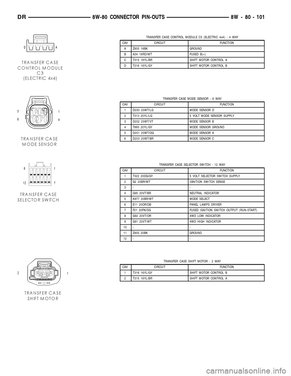
TRANSFER CASE CONTROL MODULE C3 (ELECTRIC 4x4)-4WAY
CAV CIRCUIT FUNCTION
A Z905 16BK GROUND
B A34 16RD/WT FUSED B(+)
C T315 16YL/BR SHIFT MOTOR CONTROL A
D T316 16YL/GY SHIFT MOTOR CONTROL B
TRANSFER CASE MODE SENSOR-6WAY
CAV CIRCUIT FUNCTION
1 D200 20WT/LG MODE SENSOR D
2 T313 20YL/LG 5 VOLT MODE SENSOR SUPPLY
3 D202 20WT/VT MODE SENSOR B
4 T885 20YL/GY MODE SENSOR GROUND
5 D201 20WT/DG MODE SENSOR A
6 D203 20WT/BR MODE SENSOR C
TRANSFER CASE SELECTOR SWITCH - 12 WAY
CAV CIRCUIT FUNCTION
1 T322 20DG/GY 5 VOLT SELECTOR SWITCH SUPPLY
2 G2 20BR/WT IGNITION SWITCH SENSE
3- -
4 G95 20VT/BR NEUTRAL INDICATOR
5 K977 20BR/WT MODE SELECT
6 E11 20OR/DB PANEL LAMPS DRIVER
7 F21 20PK/DG FUSED IGNITION SWITCH OUTPUT (RUN-START)
8 G92 20VT/OR 4WD LOW INDICATOR
9 G91 20VT/WT 4WD HIGH INDICATOR
10 - -
11 Z905 20BK GROUND
12 - -
TRANSFER CASE SHIFT MOTOR-2WAY
CAV CIRCUIT FUNCTION
1 T316 16YL/GY SHIFT MOTOR CONTROL B
2 T315 16YL/BR SHIFT MOTOR CONTROL A
DR8W-80 CONNECTOR PIN-OUTS 8W - 80 - 101
Page 1154 of 2627
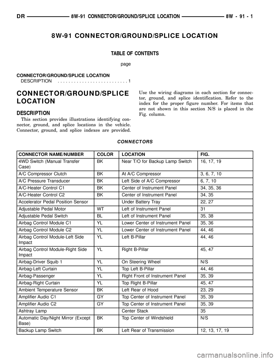
8W-91 CONNECTOR/GROUND/SPLICE LOCATION
TABLE OF CONTENTS
page
CONNECTOR/GROUND/SPLICE LOCATION
DESCRIPTION..........................1
CONNECTOR/GROUND/SPLICE
LOCATION
DESCRIPTION
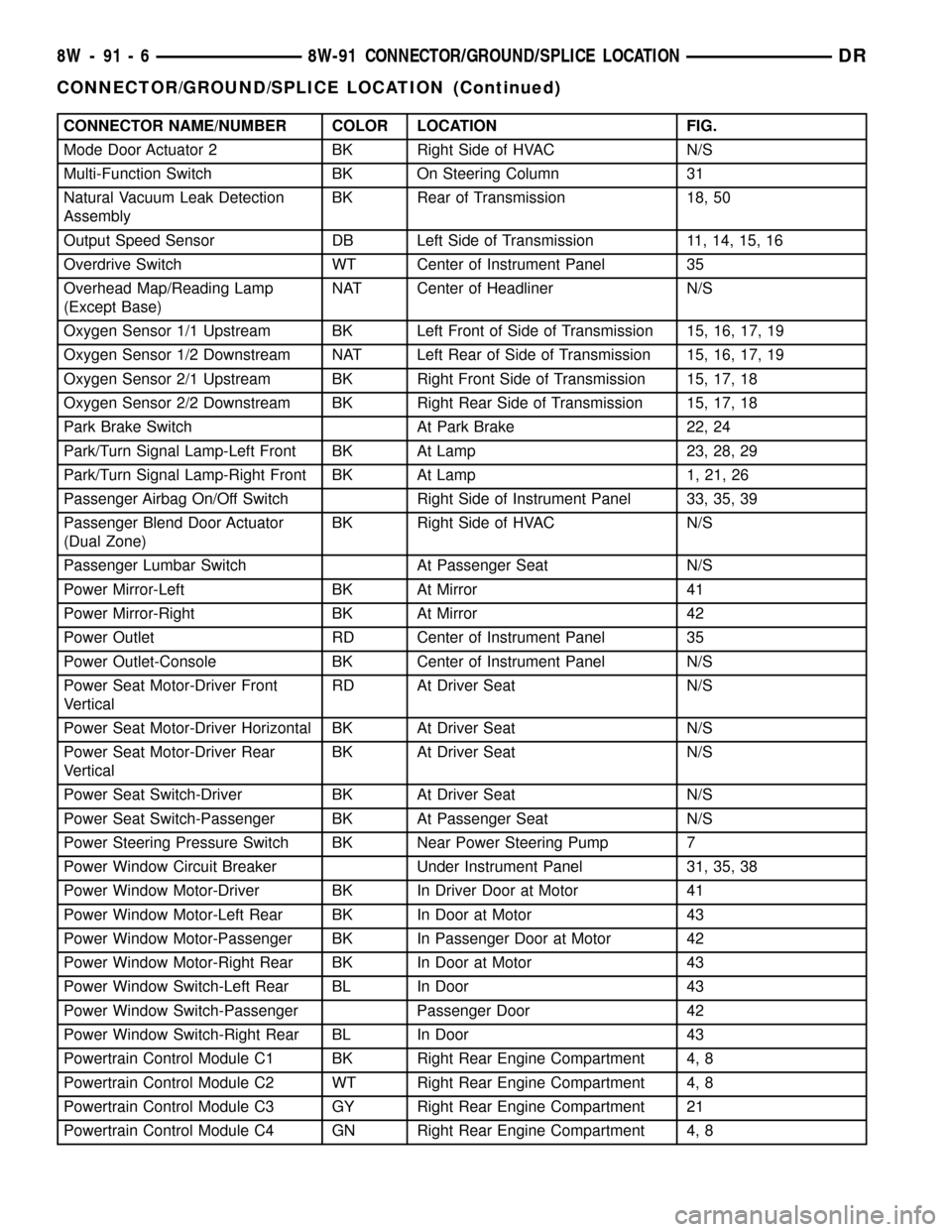
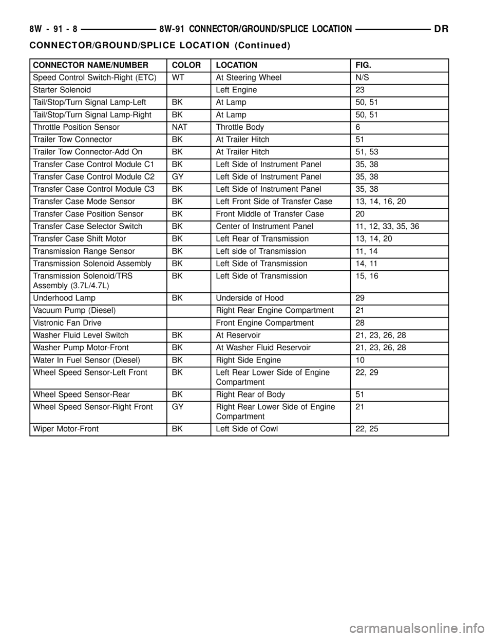
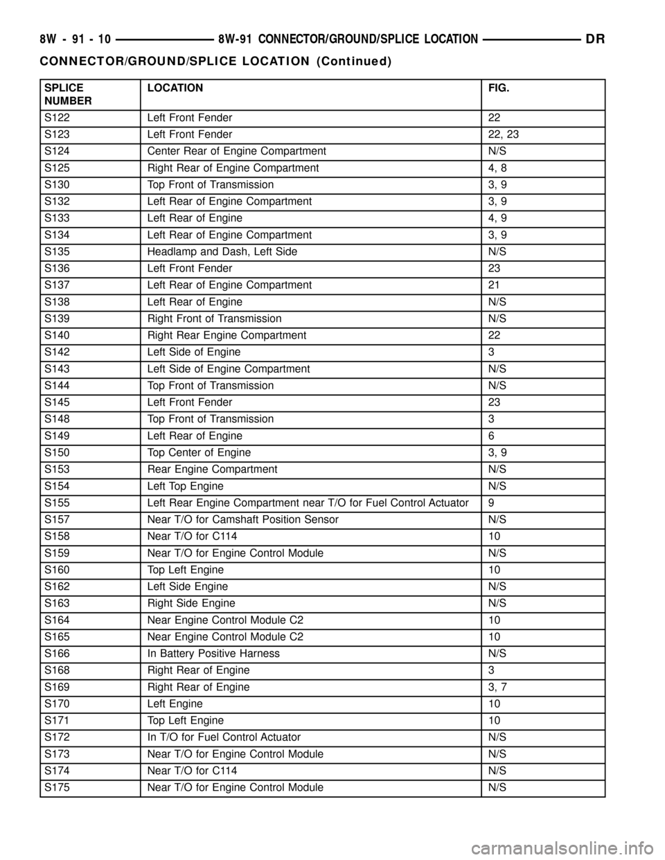
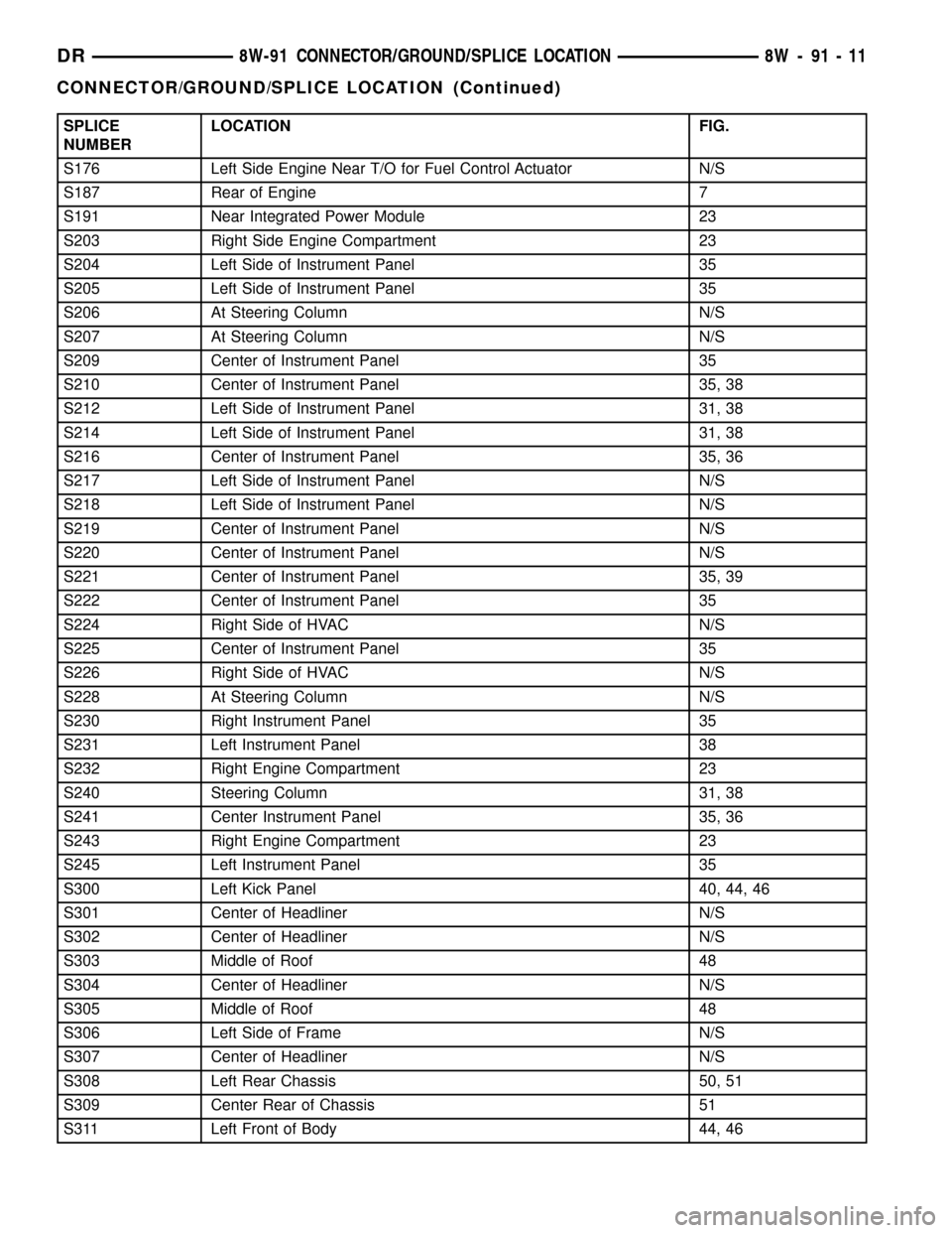
This section provides illustrations identifying con-
nector, ground, and splice locations in the vehicle.
Connector, ground, and splice indexes are provided.Use the wiring diagrams in each section for connec-
tor, ground, and splice identification. Refer to the
index for the proper figure number. For items that
are not shown in this section N/S is placed in the
Fig. column.
CONNECTORS
CONNECTOR NAME/NUMBER COLOR LOCATION FIG.
4WD Switch (Manual Transfer
Case)BK Near T/O for Backup Lamp Switch 16, 17, 19
A/C Compressor Clutch BK At A/C Compressor 3, 6, 7, 10
A/C Pressure Transducer BK Left Side of A/C Compressor 6, 7, 10
A/C-Heater Control C1 BK Center of Instrument Panel 34, 35, 36
A/C-Heater Control C2 BK Center of Instrument Panel 34, 35
Accelerator Pedal Position Sensor Under Battery Tray 22, 27
Adjustable Pedal Motor WT Left of Instrument Panel 31
Adjustable Pedal Switch BL Left of Instrument Panel 35, 38
Airbag Control Module C1 YL Lower Center of Instrument Panel 35, 36
Airbag Control Module C2 YL Lower Center of Instrument Panel 44, 46
Airbag Control Module-Left Side
ImpactYL Left B-Pillar 44, 46
Airbag Control Module-Right Side
ImpactYL Right B-Pillar 45, 47
Airbag-Driver Squib 1 YL On Steering Wheel N/S
Airbag-Left Curtain YL Top Left B-Pillar 44, 46
Airbag-Passenger YL Right Front of Instrument Panel 35, 39
Airbag-Right Curtain YL Top Right B-Pillar 45, 47
Ambient Temperature Sensor BK Left Rear of Hood 23, 29
Amplifier Audio C1 GY Top Center of Instrument Panel 35, 39
Amplifier Audio C2 GY Top Center of Instrument Panel 35, 39
Ashtray Lamp Center Stack 35
Automatic Day/Night Mirror (Except
Base)BK Top Center of Windshield N/S
Backup Lamp Switch BK Left Rear of Transmission 12, 13, 17, 19
DR8W-91 CONNECTOR/GROUND/SPLICE LOCATION 8W - 91 - 1
Page 1157 of 2627
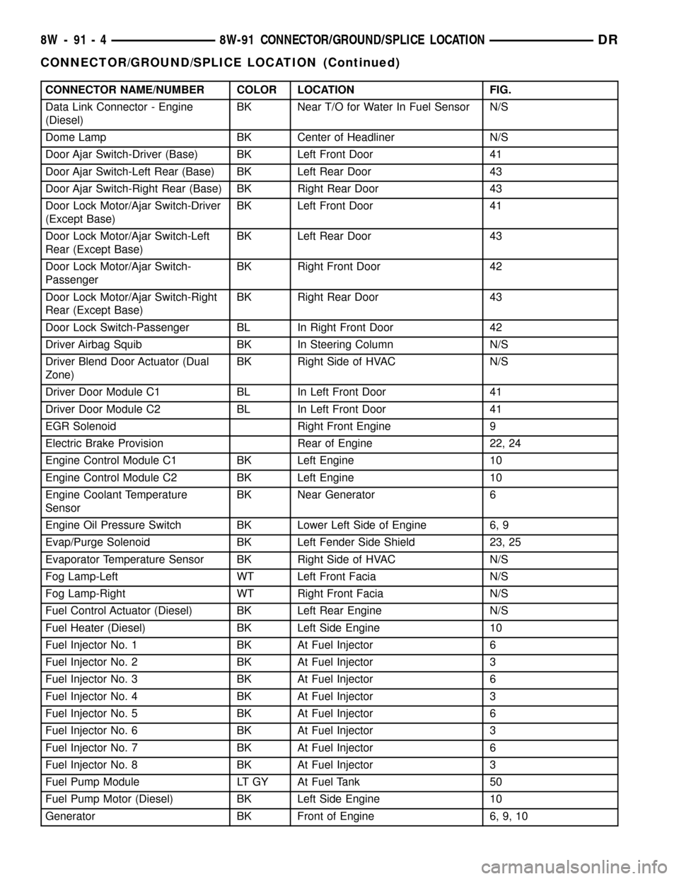
CONNECTOR NAME/NUMBER COLOR LOCATION FIG.
Data Link Connector - Engine
(Diesel)BK Near T/O for Water In Fuel Sensor N/S
Dome Lamp BK Center of Headliner N/S
Door Ajar Switch-Driver (Base) BK Left Front Door 41
Door Ajar Switch-Left Rear (Base) BK Left Rear Door 43
Door Ajar Switch-Right Rear (Base) BK Right Rear Door 43
Door Lock Motor/Ajar Switch-Driver
(Except Base)BK Left Front Door 41
Door Lock Motor/Ajar Switch-Left
Rear (Except Base)BK Left Rear Door 43
Door Lock Motor/Ajar Switch-
PassengerBK Right Front Door 42
Door Lock Motor/Ajar Switch-Right
Rear (Except Base)BK Right Rear Door 43
Door Lock Switch-Passenger BL In Right Front Door 42
Driver Airbag Squib BK In Steering Column N/S
Driver Blend Door Actuator (Dual
Zone)BK Right Side of HVAC N/S
Driver Door Module C1 BL In Left Front Door 41
Driver Door Module C2 BL In Left Front Door 41
EGR Solenoid Right Front Engine 9
Electric Brake Provision Rear of Engine 22, 24
Engine Control Module C1 BK Left Engine 10
Engine Control Module C2 BK Left Engine 10
Engine Coolant Temperature
SensorBK Near Generator 6
Engine Oil Pressure Switch BK Lower Left Side of Engine 6, 9
Evap/Purge Solenoid BK Left Fender Side Shield 23, 25
Evaporator Temperature Sensor BK Right Side of HVAC N/S
Fog Lamp-Left WT Left Front Facia N/S
Fog Lamp-Right WT Right Front Facia N/S
Fuel Control Actuator (Diesel) BK Left Rear Engine N/S
Fuel Heater (Diesel) BK Left Side Engine 10
Fuel Injector No. 1 BK At Fuel Injector 6
Fuel Injector No. 2 BK At Fuel Injector 3
Fuel Injector No. 3 BK At Fuel Injector 6
Fuel Injector No. 4 BK At Fuel Injector 3
Fuel Injector No. 5 BK At Fuel Injector 6
Fuel Injector No. 6 BK At Fuel Injector 3
Fuel Injector No. 7 BK At Fuel Injector 6
Fuel Injector No. 8 BK At Fuel Injector 3
Fuel Pump Module LT GY At Fuel Tank 50
Fuel Pump Motor (Diesel) BK Left Side Engine 10
Generator BK Front of Engine 6, 9, 10
8W - 91 - 4 8W-91 CONNECTOR/GROUND/SPLICE LOCATIONDR
CONNECTOR/GROUND/SPLICE LOCATION (Continued)
Page 1158 of 2627
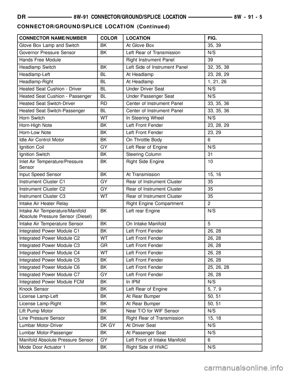
CONNECTOR NAME/NUMBER COLOR LOCATION FIG.
Glove Box Lamp and Switch BK At Glove Box 35, 39
Governor Pressure Sensor BK Left Rear of Transmission N/S
Hands Free Module Right Instrument Panel 39
Headlamp Switch BK Left Side of Instrument Panel 32, 35, 38
Headlamp-Left BL At Headlamp 23, 28, 29
Headlamp-Right BL At Headlamp 1, 21, 26
Heated Seat Cushion - Driver BL Under Driver Seat N/S
Heated Seat Cushion - Passenger BL Under Passenger Seat N/S
Heated Seat Switch-Driver RD Center of Instrument Panel 33, 35, 36
Heated Seat Switch-Passenger BL Center of Instrument Panel 33, 35, 36
Horn Switch WT In Steering Wheel N/S
Horn-High Note BK Left Front Fender 23, 28, 29
Horn-Low Note BK Left Front Fender 23, 29
Idle Air Control Motor BK On Throttle Body 6
Ignition Coil GY Left Rear of Engine N/S
Ignition Switch BK Steering Column 31
Inlet Air Temperature/Pressure
SensorBK Right Side Engine 10
Input Speed Sensor BK At Transmission 15, 16
Instrument Cluster C1 GY Rear of Instrument Cluster 35
Instrument Cluster C2 GY Rear of Instrument Cluster 35
Instrument Cluster C3 WT Rear of Instrument Cluster 35
Intake Air Heater Relay Right Engine Compartment 2
Intake Air Temperature/Manifold
Absolute Pressure Sensor (Diesel)BK Left rear Engine N/S
Intake Air Temperature Sensor BK On Intake Manifold 5
Integrated Power Module C1 BK Left Front Fender 26, 28
Integrated Power Module C2 WT Left Front Fender 26, 28
Integrated Power Module C3 GR Left Front Fender 26, 28
Integrated Power Module C4 WT Left Front Fender 26, 28
Integrated Power Module C5 BK Left Front Fender 26, 28
Integrated Power Module C6 BK Left Front Fender 25, 26, 28
Integrated Power Module C7 GY Left Front Fender 26, 28
Integrated Power Module FCM BK In IPM N/S
Knock Sensor BK Left Rear of Engine 5, 7, 9
License Lamp-Left BK At Rear Bumper 50, 51
License Lamp-Right BK At Rear Bumper 50, 51
Lift Pump Motor BK Near T/O for WIF Sensor N/S
Line Pressure Sensor BK Right Rear of Transmission 15, 18
Lumbar Motor-Driver DK GY At Driver Seat N/S
Lumbar Motor-Passenger BK At Passenger Seat N/S
Manifold Absolute Pressure Sensor GY Left Front of Intake Manifold 6
Mode Door Actuator 1 BK Right Side of HVAC N/S
DR8W-91 CONNECTOR/GROUND/SPLICE LOCATION 8W - 91 - 5
CONNECTOR/GROUND/SPLICE LOCATION (Continued)
Page 1159 of 2627
CONNECTOR NAME/NUMBER COLOR LOCATION FIG.
Mode Door Actuator 2 BK Right Side of HVAC N/S
Multi-Function Switch BK On Steering Column 31
Natural Vacuum Leak Detection
AssemblyBK Rear of Transmission 18, 50
Output Speed Sensor DB Left Side of Transmission 11, 14, 15, 16
Overdrive Switch WT Center of Instrument Panel 35
Overhead Map/Reading Lamp
(Except Base)NAT Center of Headliner N/S
Oxygen Sensor 1/1 Upstream BK Left Front of Side of Transmission 15, 16, 17, 19
Oxygen Sensor 1/2 Downstream NAT Left Rear of Side of Transmission 15, 16, 17, 19
Oxygen Sensor 2/1 Upstream BK Right Front Side of Transmission 15, 17, 18
Oxygen Sensor 2/2 Downstream BK Right Rear Side of Transmission 15, 17, 18
Park Brake Switch At Park Brake 22, 24
Park/Turn Signal Lamp-Left Front BK At Lamp 23, 28, 29
Park/Turn Signal Lamp-Right Front BK At Lamp 1, 21, 26
Passenger Airbag On/Off Switch Right Side of Instrument Panel 33, 35, 39
Passenger Blend Door Actuator
(Dual Zone)BK Right Side of HVAC N/S
Passenger Lumbar Switch At Passenger Seat N/S
Power Mirror-Left BK At Mirror 41
Power Mirror-Right BK At Mirror 42
Power Outlet RD Center of Instrument Panel 35
Power Outlet-Console BK Center of Instrument Panel N/S
Power Seat Motor-Driver Front
VerticalRD At Driver Seat N/S
Power Seat Motor-Driver Horizontal BK At Driver Seat N/S
Power Seat Motor-Driver Rear
VerticalBK At Driver Seat N/S
Power Seat Switch-Driver BK At Driver Seat N/S
Power Seat Switch-Passenger BK At Passenger Seat N/S
Power Steering Pressure Switch BK Near Power Steering Pump 7
Power Window Circuit Breaker Under Instrument Panel 31, 35, 38
Power Window Motor-Driver BK In Driver Door at Motor 41
Power Window Motor-Left Rear BK In Door at Motor 43
Power Window Motor-Passenger BK In Passenger Door at Motor 42
Power Window Motor-Right Rear BK In Door at Motor 43
Power Window Switch-Left Rear BL In Door 43
Power Window Switch-Passenger Passenger Door 42
Power Window Switch-Right Rear BL In Door 43
Powertrain Control Module C1 BK Right Rear Engine Compartment 4, 8
Powertrain Control Module C2 WT Right Rear Engine Compartment 4, 8
Powertrain Control Module C3 GY Right Rear Engine Compartment 21
Powertrain Control Module C4 GN Right Rear Engine Compartment 4, 8
8W - 91 - 6 8W-91 CONNECTOR/GROUND/SPLICE LOCATIONDR
CONNECTOR/GROUND/SPLICE LOCATION (Continued)
Page 1160 of 2627

CONNECTOR NAME/NUMBER COLOR LOCATION FIG.
PTO Switch Near G107 N/S
Radio C1 (Base) GY Rear of Radio 35, 36
Radio C1 (Premium) BK Rear of Radio 36
Radio C2 (Premium) BK Rear of Radio 36
Radio Antenna - At Antenna Base 37
Radio Antenna Cable - Right Kick Panel 36, 37
Recirculation Door Actuator BK Right Side of HVAC N/S
Red Brake Warning Indicator
SwitchBK Near Master Cylinder 22, 25, 29
Remote Radio Switch-Left BK At Steering Wheel N/S
Remote Radio Switch-Right BK At Steering Wheel N/S
Seat Belt Pretensioner-Left YL Left B-Pillar 44, 46
Seat Belt Pretensioner-Right YL Right B-Pillar 45, 47
Seat Belt Switch-Driver DK GY Left B-Pillar N/S
Seat Belt Tension Reducer
(Standard Cab)YL Left B-Pillar 44
Seat Heater Interface Module GN Under Driver Seat N/S
Sentry Key Immobilizer Module BK On Steering Column 30
Side Marker - Left Front (Dual
Wheels)BK Front of Left Rear Fender 52
Side Marker - Left Rear (Dual
Wheels)BK Rear of Left Rear Fender 52
Side Marker - Right Front (Dual
Wheels)BK Front of Right Rear Fender 52
Side Marker - Right Rear (Dual
Wheels)BK Rear of Right Rear Fender 52
Speaker-Center Instrument Panel WT Center of Instrument Panel 35, 36
Speaker-Left Front Door WT In Left Front Door 41
Speaker-Left Instrument Panel BK Left Side of Instrument Panel 35, 38
Speaker-Left Rear (Standard Cab) WT In Lower Left B-Pillar 44
Speaker-Left Rear Door (Quad
Cab)WT In Left Rear Door 43
Speaker-Right Front Door WT In Right Front Door 42
Speaker-Right Instrument Panel BK Right Side of Instrument Panel 35, 39
Speaker-Right Rear (Standard
Cab)BK In Lower Right B-Pillar 45
Speaker-Right Rear Door (Quad
Cab)BK In Right Rear Door 43
Speed Control Servo BK Left Front Side of Engine
Compartment23, 25
Speed Control Switch - Left
(Except ETC)GN Steering Wheel N/S
Speed Control Switch - Right
(Except ETC)GN Steering Wheel N/S
Speed Control Switch-Left (ETC) WT At Steering Wheel N/S
DR8W-91 CONNECTOR/GROUND/SPLICE LOCATION 8W - 91 - 7
CONNECTOR/GROUND/SPLICE LOCATION (Continued)
Page 1161 of 2627
CONNECTOR NAME/NUMBER COLOR LOCATION FIG.
Speed Control Switch-Right (ETC) WT At Steering Wheel N/S
Starter Solenoid Left Engine 23
Tail/Stop/Turn Signal Lamp-Left BK At Lamp 50, 51
Tail/Stop/Turn Signal Lamp-Right BK At Lamp 50, 51
Throttle Position Sensor NAT Throttle Body 6
Trailer Tow Connector BK At Trailer Hitch 51
Trailer Tow Connector-Add On BK At Trailer Hitch 51, 53
Transfer Case Control Module C1 BK Left Side of Instrument Panel 35, 38
Transfer Case Control Module C2 GY Left Side of Instrument Panel 35, 38
Transfer Case Control Module C3 BK Left Side of Instrument Panel 35, 38
Transfer Case Mode Sensor BK Left Front Side of Transfer Case 13, 14, 16, 20
Transfer Case Position Sensor BK Front Middle of Transfer Case 20
Transfer Case Selector Switch BK Center of Instrument Panel 11, 12, 33, 35, 36
Transfer Case Shift Motor BK Left Rear of Transmission 13, 14, 20
Transmission Range Sensor BK Left side of Transmission 11, 14
Transmission Solenoid Assembly BK Left Side of Transmission 14, 11
Transmission Solenoid/TRS
Assembly (3.7L/4.7L)BK Left Side of Transmission 15, 16
Underhood Lamp BK Underside of Hood 29
Vacuum Pump (Diesel) Right Rear Engine Compartment 21
Vistronic Fan Drive Front Engine Compartment 28
Washer Fluid Level Switch BK At Reservoir 21, 23, 26, 28
Washer Pump Motor-Front BK At Washer Fluid Reservoir 21, 23, 26, 28
Water In Fuel Sensor (Diesel) BK Right Side Engine 10
Wheel Speed Sensor-Left Front BK Left Rear Lower Side of Engine
Compartment22, 29
Wheel Speed Sensor-Rear BK Right Rear of Body 51
Wheel Speed Sensor-Right Front GY Right Rear Lower Side of Engine
Compartment21
Wiper Motor-Front BK Left Side of Cowl 22, 25
8W - 91 - 8 8W-91 CONNECTOR/GROUND/SPLICE LOCATIONDR
CONNECTOR/GROUND/SPLICE LOCATION (Continued)
Page 1163 of 2627
SPLICE
NUMBERLOCATION FIG.
S122 Left Front Fender 22
S123 Left Front Fender 22, 23
S124 Center Rear of Engine Compartment N/S
S125 Right Rear of Engine Compartment 4, 8
S130 Top Front of Transmission 3, 9
S132 Left Rear of Engine Compartment 3, 9
S133 Left Rear of Engine 4, 9
S134 Left Rear of Engine Compartment 3, 9
S135 Headlamp and Dash, Left Side N/S
S136 Left Front Fender 23
S137 Left Rear of Engine Compartment 21
S138 Left Rear of Engine N/S
S139 Right Front of Transmission N/S
S140 Right Rear Engine Compartment 22
S142 Left Side of Engine 3
S143 Left Side of Engine Compartment N/S
S144 Top Front of Transmission N/S
S145 Left Front Fender 23
S148 Top Front of Transmission 3
S149 Left Rear of Engine 6
S150 Top Center of Engine 3, 9
S153 Rear Engine Compartment N/S
S154 Left Top Engine N/S
S155 Left Rear Engine Compartment near T/O for Fuel Control Actuator 9
S157 Near T/O for Camshaft Position Sensor N/S
S158 Near T/O for C114 10
S159 Near T/O for Engine Control Module N/S
S160 Top Left Engine 10
S162 Left Side Engine N/S
S163 Right Side Engine N/S
S164 Near Engine Control Module C2 10
S165 Near Engine Control Module C2 10
S166 In Battery Positive Harness N/S
S168 Right Rear of Engine 3
S169 Right Rear of Engine 3, 7
S170 Left Engine 10
S171 Top Left Engine 10
S172 In T/O for Fuel Control Actuator N/S
S173 Near T/O for Engine Control Module N/S
S174 Near T/O for C114 N/S
S175 Near T/O for Engine Control Module N/S
8W - 91 - 10 8W-91 CONNECTOR/GROUND/SPLICE LOCATIONDR
CONNECTOR/GROUND/SPLICE LOCATION (Continued)
Page 1164 of 2627
SPLICE
NUMBERLOCATION FIG.
S176 Left Side Engine Near T/O for Fuel Control Actuator N/S
S187 Rear of Engine 7
S191 Near Integrated Power Module 23
S203 Right Side Engine Compartment 23
S204 Left Side of Instrument Panel 35
S205 Left Side of Instrument Panel 35
S206 At Steering Column N/S
S207 At Steering Column N/S
S209 Center of Instrument Panel 35
S210 Center of Instrument Panel 35, 38
S212 Left Side of Instrument Panel 31, 38
S214 Left Side of Instrument Panel 31, 38
S216 Center of Instrument Panel 35, 36
S217 Left Side of Instrument Panel N/S
S218 Left Side of Instrument Panel N/S
S219 Center of Instrument Panel N/S
S220 Center of Instrument Panel N/S
S221 Center of Instrument Panel 35, 39
S222 Center of Instrument Panel 35
S224 Right Side of HVAC N/S
S225 Center of Instrument Panel 35
S226 Right Side of HVAC N/S
S228 At Steering Column N/S
S230 Right Instrument Panel 35
S231 Left Instrument Panel 38
S232 Right Engine Compartment 23
S240 Steering Column 31, 38
S241 Center Instrument Panel 35, 36
S243 Right Engine Compartment 23
S245 Left Instrument Panel 35
S300 Left Kick Panel 40, 44, 46
S301 Center of Headliner N/S
S302 Center of Headliner N/S
S303 Middle of Roof 48
S304 Center of Headliner N/S
S305 Middle of Roof 48
S306 Left Side of Frame N/S
S307 Center of Headliner N/S
S308 Left Rear Chassis 50, 51
S309 Center Rear of Chassis 51
S311 Left Front of Body 44, 46
DR8W-91 CONNECTOR/GROUND/SPLICE LOCATION 8W - 91 - 11
CONNECTOR/GROUND/SPLICE LOCATION (Continued)
Page 1216 of 2627

8W-97 POWER DISTRIBUTION
TABLE OF CONTENTS
page page
POWER DISTRIBUTION
DESCRIPTION..........................1
OPERATION............................1
SPECIAL TOOLS
POWER DISTRIBUTION SYSTEMS.........2
CIGAR LIGHTER OUTLET
DESCRIPTION..........................2
OPERATION............................2
DIAGNOSIS AND TESTING - CIGAR LIGHTER
OUTLET.............................2
INTEGRATED POWER MODULE
DESCRIPTION..........................3
OPERATION............................3
REMOVAL.............................3
INSTALLATION..........................4
FRONT CONTROL MODULE
DESCRIPTION..........................5OPERATION............................5
DIAGNOSIS AND TESTING - FRONT
CONTROL MODULE....................5
REMOVAL.............................6
INSTALLATION..........................6
IOD FUSE
DESCRIPTION..........................6
OPERATION............................6
REMOVAL.............................7
INSTALLATION..........................7
POWER OUTLET
DESCRIPTION..........................7
OPERATION............................7
DIAGNOSIS AND TESTING - POWER
OUTLET.............................7
REMOVAL.............................8
INSTALLATION..........................8
POWER DISTRIBUTION
DESCRIPTION
This group covers the various standard and
optional power distribution components used on this
model. The power distribution system for this vehicle
consists of the following components:
²Integrated Power Module (IPM)
²Front Control Module (FCM)
²Power Distribution Center (PDC)
²Power Outlets
²Cigar Lighter Outlets
²Relays
Refer to Wiring Diagrams for complete circuit sche-
matics.
The power distribution system also incorporates
various types of circuit control and protection fea-
tures, including:
²Automatic resetting circuit breakers
²Blade-type fuses
²Cartridge fuses
²Relays
Following are general descriptions of the major
components in the power distribution system. See the
owner's manual in the vehicle glove box for more
information on the features and use of all of the
power distribution system components.
OPERATION
The power distribution system for this vehicle is
designed to provide safe, reliable, and centralized dis-
tribution points for the electrical current required to
operate all of the many standard and optional facto-
ry-installed electrical and electronic powertrain,
chassis, safety, security, comfort and convenience sys-
tems. At the same time, the power distribution sys-
tem was designed to provide ready access to these
electrical distribution points for the vehicle techni-
cian to use when conducting diagnosis and repair of
faulty circuits. The power distribution system can
also prove useful for the sourcing of additional elec-
trical circuits that may be required to provide the
electrical current needed to operate many accessories
that the vehicle owner may choose to have installed
in the aftermarket.
DR8W-97 POWER DISTRIBUTION 8W - 97 - 1