module DODGE RAM 1500 1998 2.G Workshop Manual
[x] Cancel search | Manufacturer: DODGE, Model Year: 1998, Model line: RAM 1500, Model: DODGE RAM 1500 1998 2.GPages: 2627
Page 1234 of 2627
(12) Disconnect heater hoses from heater core and
remove hose assembly.
(13) Disconnect throttle and speed control cables.
(14) Remove upper radiator hose from engine.
(15) Remove lower radiator hose from engine.
(16) Remove radiator/cooling module assembly.
(17) Disconnect the engine to body ground straps
at the left side of cowl.
(18) Disconnect the engine wiring harness at the
following points:
²Intake air temperature (IAT) sensor
²Fuel Injectors
²Throttle Position (TPS) Switch
²Idle Air Control (IAC) Motor
²Engine Oil Pressure Switch
²Engine Coolant Temperature (ECT) Sensor
²Manifold Absolute Pressure MAP) Sensor
²Camshaft Position (CMP) Sensor
²Coil Over Plugs
²Crankshaft Position Sensor
(19) Remove coil over plugs.
(20) Release fuel rail pressure.
(21) Remove fuel rail and secure away from
engine.
NOTE: It is not necessary to release the quick con-
nect fitting from the fuel supply line for engine
removal.
(22) Remove the PCV hose.
(23) Remove the breather hoses.
(24) Remove the vacuum hose for the power brake
booster.
(25) Disconnect knock sensors.
(26) Remove engine oil dipstick tube.
(27) Remove intake manifold.
(28) Install engine lifting fixture,special tool#8247,
using original fasteners from the removed intake
manifold, and fuel rail. Torque to factory specifica-
tions.
NOTE: Recheck bolt torque for engine lift plate
before removing engine.
(29) Secure the left and right engine wiring har-
nesses away from engine.
(30) Raise vehicle.
(31) Disconnect oxygen sensor wiring.
(32) Disconnect crankshaft postion sensor.
(33) Disconnect the engine block heater power
cable, if equipped.
(34) Disconnect the front propshaft at the front
differential and secure out of way.
NOTE: It is necessary to disconnect the front prop-
shaft for access to the starter and left side exhaust
flange.(35) Remove the starter.
(36) Remove the ground straps from the left and
right side of the block.
(37) Disconnect the right and left exhaust pipes at
the manifolds and from the crossover, and remove
from the vehicle.
NOTE: The exhaust clamps at the manifolds cannot
be reused. New clamps must be used or leaks may
occur.
(38) Remove the structural cover.
(39) Remove torque convertor bolts, and mark
location for reassembly.
(40) Remove transmission bellhousing to engine
bolts.
(41) Remove left and right engine mount thru
bolts.
(42) Lower the vehicle.
(43) Support the transmission with a suitable jack.
(44) Connect a suitable engine hoist to the engine
lift plate.
(45) Remove engine from vehicle.
INSTALLATION
(1) Position the engine in the vehicle.
(2) Install both left and right side engine mounts
onto engine.
(3) Raise the vehicle.
(4) Install the transmission bellhousing to engine
mounting bolts. Tighten the bolts to 41 N´m (30ft.
lbs.).
(5) Tighten the engine mount thru bolts.
(6) Install the torque convertor bolts.
(7) Connect the ground straps on the left and right
side of the engine.
(8) Install the starter.
(9) Connect the crankshaft position sensor.
(10) Install the engine block heater power cable, if
equipped.
CAUTION: The structural cover requires a specific
torque sequence. Failure to follow this sequence
may cause severe damage to the cover.
(11) Install the structural cover.
NOTE: New clamps must be used on exhaust man-
ifold flanges. Failure to use new clamps may result
in exhaust leaks.
(12) Install the left and right exhaust pipes.
(13) Connect the left and right oxygen sensors.
(14) Lower vehicle.
(15) Remove the engine lift plate.
(16) Connect the knock sensors.
DRENGINE - 3.7L 9 - 11
ENGINE - 3.7L (Continued)
Page 1235 of 2627
(17) Connect the engine to body ground straps at
the left side of the cowl.
(18) Install the intake manifold.
(19) Install the engine oil dipstick tube.
(20) Install the power brake booster vacuum hose.
(21) Install the breather hoses.
(22) Install the PCV hose.
(23) Install the fuel rail.
(24) Install the coil over plugs.
(25) Connect the engine wiring harness at the fol-
lowing points:
²Intake air temperature (IAT) sensor
²Fuel Injectors
²Throttle Position (TPS) Switch
²Idle Air Control (IAC) Motor
²Engine Oil Pressure Switch
²Engine Coolant Temperature (ECT) Sensor
²Manifold Absolute Pressure MAP) Sensor
²Camshaft Position (CMP) Sensor
²Coil Over Plugs
²Crankshaft Position Sensor
(26) Reinstall the radiator/cooling module assem-
bly.
(27) Connect lower radiator hose.
(28) Connect upper radiator hose.
(29) Connect throttle and speed control cables.
(30) Install the heater hose assembly.
(31) Install coolant recovery bottle.
(32) Install the power steering pump.
(33) Install the generator.
(34) Install the A/C compressor.
(35) Install the drive belt.
(36) Install the fan shroud with the viscous fan
assembly.
(37) Install the radiator core support bracket.
(38) Install the air cleaner assembly.
(39) Refill the engine cooling system.
(40) Recharge the air conditioning.
(41) Install the hood.
(42) Check and fill engine oil.
(43) Connect the battery negative cable.
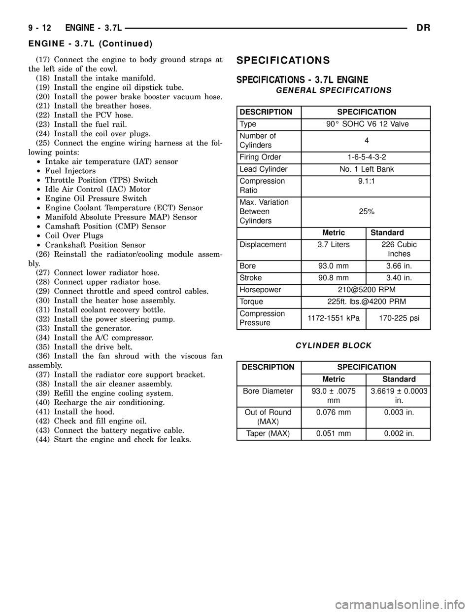
(44) Start the engine and check for leaks.SPECIFICATIONS
SPECIFICATIONS - 3.7L ENGINE
GENERAL SPECIFICATIONS
DESCRIPTION SPECIFICATION
Type 90É SOHC V6 12 Valve
Number of
Cylinders4
Firing Order 1-6-5-4-3-2
Lead Cylinder No. 1 Left Bank
Compression
Ratio9.1:1
Max. Variation
Between
Cylinders25%
Metric Standard
Displacement 3.7 Liters 226 Cubic
Inches
Bore 93.0 mm 3.66 in.
Stroke 90.8 mm 3.40 in.
Horsepower 210@5200 RPM
Torque 225ft. lbs.@4200 PRM
Compression
Pressure1172-1551 kPa 170-225 psi
CYLINDER BLOCK
DESCRIPTION SPECIFICATION
Metric Standard
Bore Diameter 93.0 .0075
mm3.6619 0.0003
in.
Out of Round
(MAX)0.076 mm 0.003 in.
Taper (MAX) 0.051 mm 0.002 in.
9 - 12 ENGINE - 3.7LDR
ENGINE - 3.7L (Continued)
Page 1290 of 2627
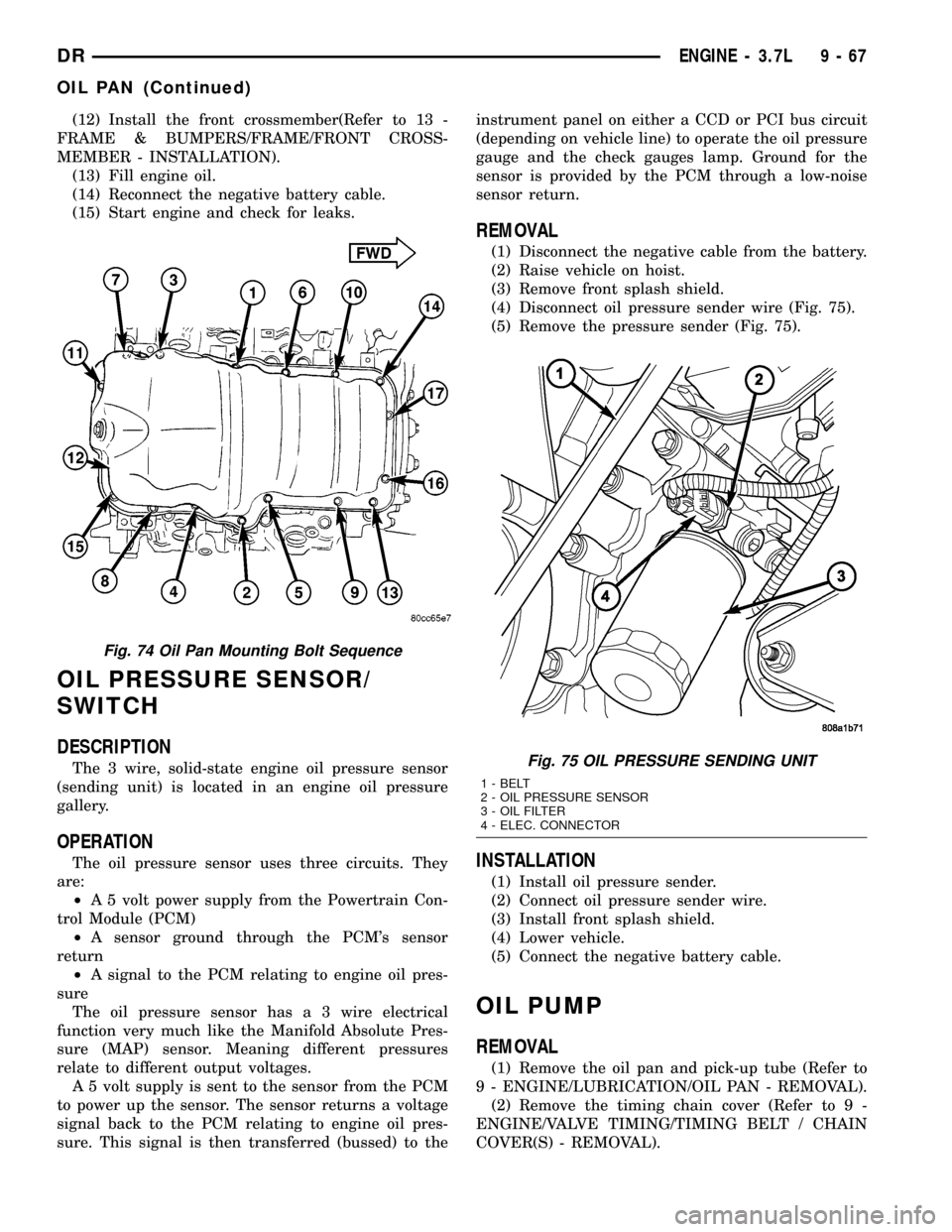
(12) Install the front crossmember(Refer to 13 -
FRAME & BUMPERS/FRAME/FRONT CROSS-
MEMBER - INSTALLATION).
(13) Fill engine oil.
(14) Reconnect the negative battery cable.
(15) Start engine and check for leaks.
OIL PRESSURE SENSOR/
SWITCH
DESCRIPTION
The 3 wire, solid-state engine oil pressure sensor
(sending unit) is located in an engine oil pressure
gallery.
OPERATION
The oil pressure sensor uses three circuits. They
are:
²A 5 volt power supply from the Powertrain Con-
trol Module (PCM)
²A sensor ground through the PCM's sensor
return
²A signal to the PCM relating to engine oil pres-
sure
The oil pressure sensor has a 3 wire electrical
function very much like the Manifold Absolute Pres-
sure (MAP) sensor. Meaning different pressures
relate to different output voltages.
A 5 volt supply is sent to the sensor from the PCM
to power up the sensor. The sensor returns a voltage
signal back to the PCM relating to engine oil pres-
sure. This signal is then transferred (bussed) to theinstrument panel on either a CCD or PCI bus circuit
(depending on vehicle line) to operate the oil pressure
gauge and the check gauges lamp. Ground for the
sensor is provided by the PCM through a low-noise
sensor return.
REMOVAL
(1) Disconnect the negative cable from the battery.
(2) Raise vehicle on hoist.
(3) Remove front splash shield.
(4) Disconnect oil pressure sender wire (Fig. 75).
(5) Remove the pressure sender (Fig. 75).
INSTALLATION
(1) Install oil pressure sender.
(2) Connect oil pressure sender wire.
(3) Install front splash shield.
(4) Lower vehicle.
(5) Connect the negative battery cable.
OIL PUMP
REMOVAL
(1) Remove the oil pan and pick-up tube (Refer to
9 - ENGINE/LUBRICATION/OIL PAN - REMOVAL).
(2) Remove the timing chain cover (Refer to 9 -
ENGINE/VALVE TIMING/TIMING BELT / CHAIN
COVER(S) - REMOVAL).
Fig. 74 Oil Pan Mounting Bolt Sequence
Fig. 75 OIL PRESSURE SENDING UNIT
1 - BELT
2 - OIL PRESSURE SENSOR
3 - OIL FILTER
4 - ELEC. CONNECTOR
DRENGINE - 3.7L 9 - 67
OIL PAN (Continued)
Page 1379 of 2627
OIL PRESSURE SENSOR/
SWITCH
DESCRIPTION
DESCRIPTION
The 3 wire, solid-state engine oil pressure sensor
(sending unit) is located in an engine oil pressure
gallery.
DESCRIPTION
The 3±wire, electrical/mechanical engine oil pres-
sure sensor (sending unit) is located in an engine oil
pressure gallery.
OPERATION
OPERATION
The oil pressure sensor uses three circuits. They
are:
²A 5 volt power supply from the Powertrain Con-
trol Module (PCM)
²A sensor ground through the PCM's sensor
return
²A signal to the PCM relating to engine oil pres-
sure
The oil pressure sensor has a 3 wire electrical
function very much like the Manifold Absolute Pres-
sure (MAP) sensor. Meaning different pressures
relate to different output voltages.
A 5 volt supply is sent to the sensor from the PCM
to power up the sensor. The sensor returns a voltage
signal back to the PCM relating to engine oil pres-
sure. This signal is then transferred (bussed) to the
instrument panel on either a CCD or PCI bus circuit
(depending on vehicle line) to operate the oil pressure
gauge and the check gauges lamp. Ground for the
sensor is provided by the PCM through a low-noise
sensor return.
OPERATION
The oil pressure sensor uses two circuits. They are:
²A signal to the PCM relating to engine oil pres-
sure
²A sensor ground through the PCM's sensor
return
The oil pressure sensor returns a voltage signal
back to the PCM relating to engine oil pressure. This
signal is then transferred (bussed) to the instrument
panel on a CCD bus circuit to operate the oil pres-
sure gauge and the check gauges lamp. Ground for
the sensor is provided by the PCM through a low-
noise sensor return.
REMOVAL
(1) Disconnect the negative cable from the battery.
(2) Raise vehicle on hoist.
(3) Remove front splash shield.
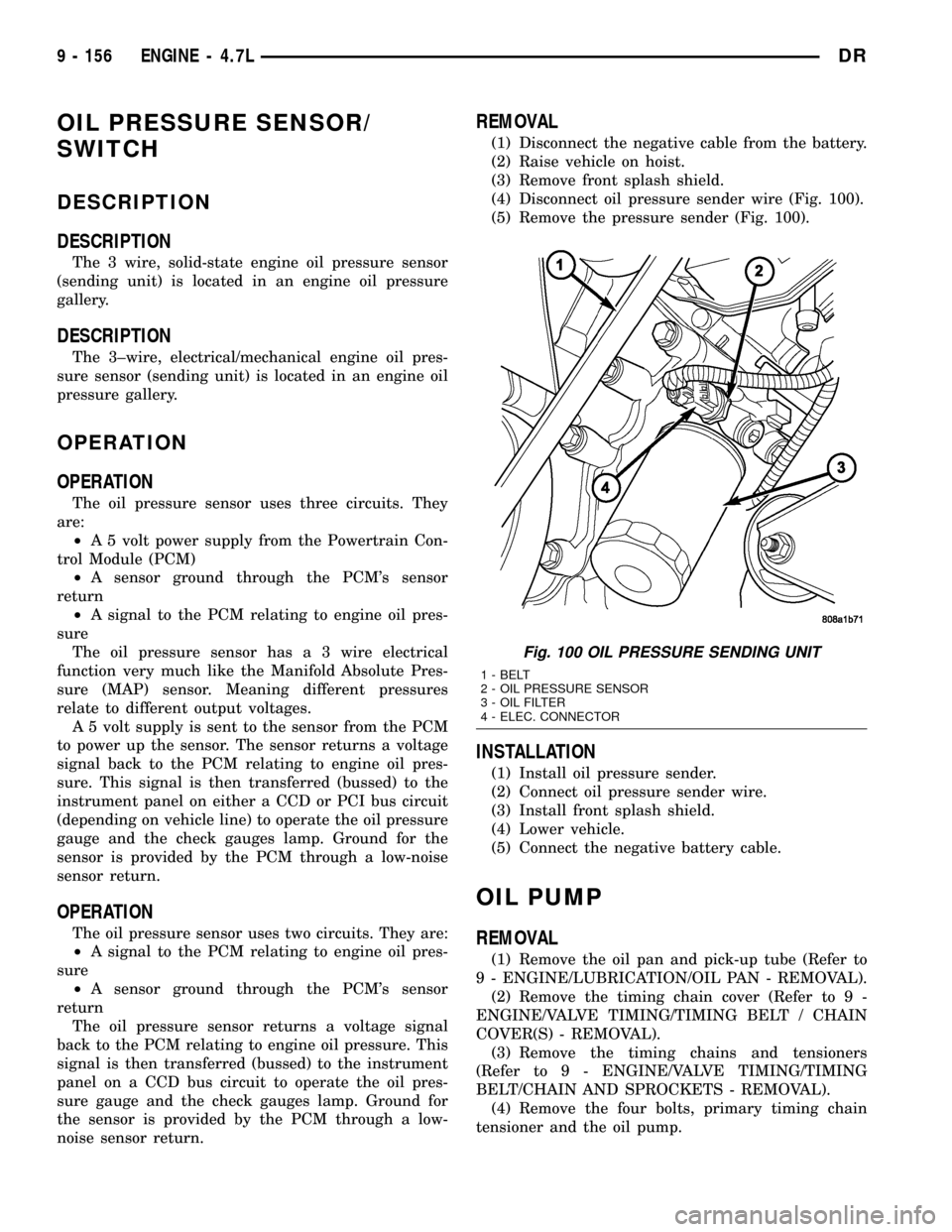
(4) Disconnect oil pressure sender wire (Fig. 100).
(5) Remove the pressure sender (Fig. 100).
INSTALLATION
(1) Install oil pressure sender.
(2) Connect oil pressure sender wire.
(3) Install front splash shield.
(4) Lower vehicle.
(5) Connect the negative battery cable.
OIL PUMP
REMOVAL
(1) Remove the oil pan and pick-up tube (Refer to
9 - ENGINE/LUBRICATION/OIL PAN - REMOVAL).
(2) Remove the timing chain cover (Refer to 9 -
ENGINE/VALVE TIMING/TIMING BELT / CHAIN
COVER(S) - REMOVAL).
(3) Remove the timing chains and tensioners
(Refer to 9 - ENGINE/VALVE TIMING/TIMING
BELT/CHAIN AND SPROCKETS - REMOVAL).
(4) Remove the four bolts, primary timing chain
tensioner and the oil pump.
Fig. 100 OIL PRESSURE SENDING UNIT
1 - BELT
2 - OIL PRESSURE SENSOR
3 - OIL FILTER
4 - ELEC. CONNECTOR
9 - 156 ENGINE - 4.7LDR
Page 1459 of 2627
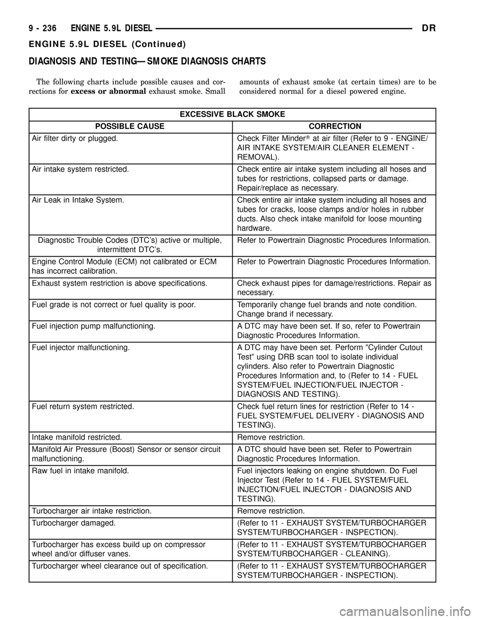
DIAGNOSIS AND TESTINGÐSMOKE DIAGNOSIS CHARTS
The following charts include possible causes and cor-
rections forexcess or abnormalexhaust smoke. Smallamounts of exhaust smoke (at certain times) are to be
considered normal for a diesel powered engine.
EXCESSIVE BLACK SMOKE
POSSIBLE CAUSE CORRECTION
Air filter dirty or plugged. Check Filter MinderTat air filter (Refer to 9 - ENGINE/
AIR INTAKE SYSTEM/AIR CLEANER ELEMENT -
REMOVAL).
Air intake system restricted. Check entire air intake system including all hoses and
tubes for restrictions, collapsed parts or damage.
Repair/replace as necessary.
Air Leak in Intake System. Check entire air intake system including all hoses and
tubes for cracks, loose clamps and/or holes in rubber
ducts. Also check intake manifold for loose mounting
hardware.
Diagnostic Trouble Codes (DTC's) active or multiple,
intermittent DTC's.Refer to Powertrain Diagnostic Procedures Information.
Engine Control Module (ECM) not calibrated or ECM
has incorrect calibration.Refer to Powertrain Diagnostic Procedures Information.
Exhaust system restriction is above specifications. Check exhaust pipes for damage/restrictions. Repair as
necessary.
Fuel grade is not correct or fuel quality is poor. Temporarily change fuel brands and note condition.
Change brand if necessary.
Fuel injection pump malfunctioning. A DTC may have been set. If so, refer to Powertrain
Diagnostic Procedures Information.
Fuel injector malfunctioning. A DTC may have been set. Perform9Cylinder Cutout
Test9using DRB scan tool to isolate individual
cylinders. Also refer to Powertrain Diagnostic
Procedures Information and, to (Refer to 14 - FUEL
SYSTEM/FUEL INJECTION/FUEL INJECTOR -
DIAGNOSIS AND TESTING).
Fuel return system restricted. Check fuel return lines for restriction (Refer to 14 -
FUEL SYSTEM/FUEL DELIVERY - DIAGNOSIS AND
TESTING).
Intake manifold restricted. Remove restriction.
Manifold Air Pressure (Boost) Sensor or sensor circuit
malfunctioning.A DTC should have been set. Refer to Powertrain
Diagnostic Procedures Information.
Raw fuel in intake manifold. Fuel injectors leaking on engine shutdown. Do Fuel
Injector Test (Refer to 14 - FUEL SYSTEM/FUEL
INJECTION/FUEL INJECTOR - DIAGNOSIS AND
TESTING).
Turbocharger air intake restriction. Remove restriction.
Turbocharger damaged. (Refer to 11 - EXHAUST SYSTEM/TURBOCHARGER
SYSTEM/TURBOCHARGER - INSPECTION).
Turbocharger has excess build up on compressor
wheel and/or diffuser vanes.(Refer to 11 - EXHAUST SYSTEM/TURBOCHARGER
SYSTEM/TURBOCHARGER - CLEANING).
Turbocharger wheel clearance out of specification. (Refer to 11 - EXHAUST SYSTEM/TURBOCHARGER
SYSTEM/TURBOCHARGER - INSPECTION).
9 - 236 ENGINE 5.9L DIESELDR
ENGINE 5.9L DIESEL (Continued)
Page 1460 of 2627
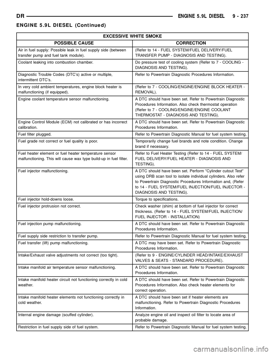
EXCESSIVE WHITE SMOKE
POSSIBLE CAUSE CORRECTION
Air in fuel supply: Possible leak in fuel supply side (between
transfer pump and fuel tank module).(Refer to 14 - FUEL SYSTEM/FUEL DELIVERY/FUEL
TRANSFER PUMP - DIAGNOSIS AND TESTING).
Coolant leaking into combustion chamber. Do pressure test of cooling system (Refer to 7 - COOLING -
DIAGNOSIS AND TESTING).
Diagnostic Trouble Codes (DTC's) active or multiple,
intermittent DTC's.Refer to Powertrain Diagnostic Procedures Information.
In very cold ambient temperatures, engine block heater is
malfunctioning (if equipped).(Refer to 7 - COOLING/ENGINE/ENGINE BLOCK HEATER -
REMOVAL).
Engine coolant temperature sensor malfunctioning. A DTC should have been set. Refer to Powertrain Diagnostic
Procedures Information. Also check thermostat operation
(Refer to 7 - COOLING/ENGINE/ENGINE COOLANT
THERMOSTAT - DIAGNOSIS AND TESTING).
Engine Control Module (ECM) not calibrated or has incorrect
calibration.A DTC should have been set. Refer to Powertrain Diagnostic
Procedures Information.
Fuel filter plugged. Refer to Powertrain Diagnostic Manual for fuel system testing.
Fuel grade not correct or fuel quality is poor. Temporarily change fuel brands and note condition. Change
brand if necessary.
Fuel heater element or fuel heater temperature sensor
malfunctioning. This will cause wax type build-up in fuel filter.Refer to Fuel Heater Testing (Refer to 14 - FUEL SYSTEM/
FUEL DELIVERY/FUEL HEATER - DIAGNOSIS AND
TESTING).
Fuel injector malfunctioning. A DTC should have been set. Perform9Cylinder cutout Test9
using DRB scan tool to isolate individual cylinders. Also refer
to Powertrain Diagnostic Procedures Information and, (Refer
to 14 - FUEL SYSTEM/FUEL INJECTION/FUEL INJECTOR -
DIAGNOSIS AND TESTING).
Fuel injector hold-downs loose. Torque to specifications.
Fuel injector protrusion not correct. Check washer (shim) at bottom of fuel injector for correct
thickness. (Refer to 14 - FUEL SYSTEM/FUEL INJECTION/
FUEL INJECTOR - INSTALLATION)
Fuel injection pump malfunctioning. A DTC should have been set. Refer to Powertrain Diagnostic
Procedures Information.
Fuel supply side restriction to transfer pump. Refer to Powertrain Diagnostic Manual for fuel system testing.
Fuel transfer (lift) pump malfunctioning. A DTC may have been set. Refer to Powertrain Diagnostic
Procedures Information.
Intake/Exhaust valve adjustments not correct (too tight). (Refer to 9 - ENGINE/CYLINDER HEAD/INTAKE/EXHAUST
VALVES & SEATS - STANDARD PROCEDURE).
Intake manifold air temperature sensor malfunctioning. A DTC should have been set. Refer to Powertrain Diagnostic
Procedures Information.
Intake manifold heater circuit not functioning correctly in cold
weather.A DTC should have been set. Refer to Powertrain Diagnostic
Procedures Information. Also check heater elements for
correct operation.
Intake manifold heater elements not functioning correctly in
cold weather.A DTC should have been set if heater elements are
malfunctioning. Refer to Powertrain Diagnostic Procedures
Information.
Internal engine damage (scuffed cylinder). Analyze engine oil and inspect oil filter to locate area of
probable damage.
Restriction in fuel supply side of fuel system. Refer to Powertrain Diagnostic Manual for fuel system testing.
DRENGINE 5.9L DIESEL 9 - 237
ENGINE 5.9L DIESEL (Continued)
Page 1554 of 2627
STANDARD PROCEDURE - HYDROFORM
FENDER RAIL REPAIR
CAUTION: This repair procedure assumes damage
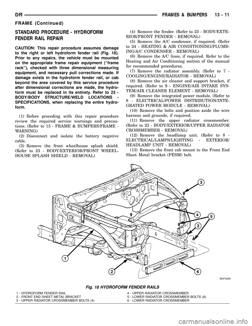
to the right or left hydroform fender rail (Fig. 18).
Prior to any repairs, the vehicle must be mounted
on the appropriate frame repair equipment (ªframe
rackº), checked with three dimensional measuring
equipment, and necessary pull corrections made. If
damage exists in the hydroform fender rail, or cab
beyond the area covered by this service procedure
after dimensional corrections are made, the hydro-
form must be replaced in its entirety. Refer to 23 -
BODY/BODY STRUCTURE/WELD LOCATIONS -
SPECIFICATIONS, when replacing the entire hydro-
form.
(1) Before proceding with this repair procedure
review the required service warnings and precau-
tions. (Refer to 13 - FRAME & BUMPERS/FRAME -
WARNING)
(2) Disconnect and isolate the battery negative
cable.
(3) Remove the front wheelhouse splash shield.
(Refer to 23 - BODY/EXTERIOR/FRONT WHEEL-
HOUSE SPLASH SHIELD - REMOVAL)(4) Remove the fender. (Refer to 23 - BODY/EXTE-
RIOR/FRONT FENDER - REMOVAL)
(5) Remove the A/C condenser, if required. (Refer
to 24 - HEATING & AIR CONDITIONING/PLUMB-
ING/A/C CONDENSER - REMOVAL)
(6) Remove the A/C lines, if required. Refer to the
Heating and Air Conditioning section of the manual
for recommended procedures.
(7) Remove the radiator assembly. (Refer to 7 -
COOLING/ENGINE/RADIATOR - REMOVAL)
(8) Remove the air cleaner and support bracket, if
required. (Refer to 9 - ENGINE/AIR INTAKE SYS-
TEM/AIR CLEANER ELEMENT - REMOVAL)
(9) Remove the integrated power module. (Refer to
8 - ELECTRICAL/POWER DISTRIBUTION/INTE-
GRATED POWER MODULE - REMOVAL)
(10) Remove the bolts and position aside the wire
harness and grounds, if required.
(11) Remove the upper radiator crossmember.
(Refer to 23 - BODY/EXTERIOR/UPPER RADIATOR
CROSSMEMBER - REMOVAL)
(12) Remove the headlamp unit. (Refer to 8 -
ELECTRICAL/LAMPS/LIGHTING - EXTERIOR/
HEADLAMP UNIT - REMOVAL)
(13) Remove the front cab mount to the Front End
Sheet Metal bracket (FESM) bolt.
Fig. 18 HYDROFORM FENDER RAILS
1 - HYDROFORM FENDER RAIL
2 - FRONT END SHEET METAL BRACKET
3 - UPPER RADIATOR CROSSMEMBER BOLTS (4)4 - UPPER RADIATOR CROSSMEMBER
5 - LOWER RADIATOR CROSSMEMBER BOLTS (8)
6 - LOWER RADIATOR CROSSMEMBER
DRFRAMES & BUMPERS 13 - 11
FRAME (Continued)
Page 1555 of 2627
(14) Remove the bolts attaching the lower radiator
crossmember to the hydroform fender rail. (Fig. 18)
CAUTION: Do not use any flame or plasma cutting
equipment to cut the frame in this procedure. The
inaccurate and high temperatures achieved during
flame or plasma cutting will change the metal char-
acteristics and may weaken the frame and/or repair
location.
(15) Using a reciprocating saw or equivalent, cut
the fender rail and shotgun at a straight and square
section of the hydroform and remove.
(16) Smooth and square the cut edges.
(17) Using the damaged structure as a reference
cut the service part at the same location as the first
cut. Smooth and square the cut edges.
NOTE: The repair structure should butt up to the
remaining structure and provide the same overall
vehicle geometry.
(18) Fabricate 51 mm (2.0 in.) long repair inserts
using scrap from the old structure or the replacement
part. It will be necessary to split the inserts on each
of their four sides to fit into the hydroform.
(19) Remove any paint or e-coat from the inserts
and also to the interior and exterior of the hydro-
forms.
(20) Cut plug weld holes as described below.
²On the upper rail, cut one 13 mm (0.5 in.) hole
on each side of the rail, 25 mm (1.0 in.) from the butt
joint of the tubes.
²On the lower rail, cut one 13 mm (0.5 in.) hole
on the top and bottom sides of the rail 25 mm (1.0
in.) from the butt joint of the tube.
²On the lower rail, cut two 13 mm (0.5 in.) holes
on the inner and outer sides of the rail 25 mm (1.0
in.) from the butt joint of the tube.
CAUTION: Shield the surrounding area and compo-
nents from exposure to the welding spatter and
heat.
(21) Install the insert 1º into the replacement part
and tack into place with a weld. (Refer to 13 -
FRAME & BUMPERS/FRAME - SPECIFICATIONS -
WELDING)
(22) Insert the service part into place and using
the appropriate measuring equipment, verify the
front end sheet metal bracket's location in all three
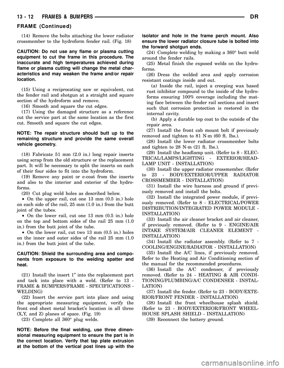
(X,Y, and Z) planes of space. (Fig. 19)
(23) Complete all 360É plug welds.
NOTE: Before the final welding, use three dimen-
sional measuring equipment to ensure the part is in
the correct location. Verify that tap plate extrusion
at the bottom of the vertical post lines up with theisolator and hole in the frame perch mount. Also
ensure the lower radiator closure tube is bolted into
the forward shotgun ends.
(24) Complete welding by making a 360É butt weld
around the fender rails.
(25) Metal finish the exposed welds on the hydro-
forms.
(26) Dress the welded area and apply corrosion
resistant coatings inside and out.
(a) Inside the rail, inject a creeping wax based
rust inhibitor compound to the inside of the hydro-
forms ensuring 100% coverage including the mat-
ing face between the fender rail sections and insert
such that corrosion protection is restored in the
internal cavity.
(b) Apply a durable top coat to the outside of the
repair area.
(27) Install the front cab mount bolt if previously
removed and tighten to 81 N´m (60 ft. lbs.).
(28) Install the lower radiator crossmember bolts
and tighten to 28 N´m (21 ft. lbs.).
(29) Install the headlamp unit. (Refer to 8 - ELEC-
TRICAL/LAMPS/LIGHTING - EXTERIOR/HEAD-
LAMP UNIT - INSTALLATION)
(30) Install the upper radiator crossmember. (Refer
to 23 - BODY/EXTERIOR/UPPER RADIATOR
CROSSMEMBER - INSTALLATION)
(31) Install the wire harness and ground if previ-
ously removed and install the bolts.
(32) Install the integrated power module, if previ-
ously removed. (Refer to 8 - ELECTRICAL/POWER
DISTRIBUTION/INTEGRATED POWER MODULE -
INSTALLATION)
(33) Install the air cleaner bracket and air cleaner,
if previously removed. (Refer to 9 - ENGINE/AIR
INTAKE SYSTEM/AIR CLEANER ELEMENT -
INSTALLATION)
(34) Install the radiator assembly. (Refer to 7 -
COOLING/ENGINE/RADIATOR - INSTALLATION)
(35) Install the A/C lines, if previously removed.
Refer to the Heating and Air Conditioning section of
the manual for the recommended procedures.
(36) Install the A/C condenser, if previously
removed. (Refer to 24 - HEATING & AIR CONDI-
TIONING/PLUMBING/A/C CONDENSER - INSTAL-
LATION)
(37) Install the fender. (Refer to 23 - BODY/EXTE-
RIOR/FRONT FENDER - INSTALLATION)
(38) Install the front wheelhouse splash shield.
(Refer to 23 - BODY/EXTERIOR/FRONT WHEEL-
HOUSE SPLASH SHIELD - INSTALLATION)
(39) Reconnect the battery ground.
13 - 12 FRAMES & BUMPERSDR
FRAME (Continued)
Page 1570 of 2627
FUEL SYSTEM
TABLE OF CONTENTS
page page
FUEL DELIVERY - GAS....................1
FUEL INJECTION - GAS...................21FUEL DELIVERY - DIESEL.................44
FUEL INJECTION - DIESEL................68
FUEL DELIVERY - GAS
TABLE OF CONTENTS
page page
FUEL DELIVERY - GAS
DESCRIPTION..........................1
OPERATION............................2
STANDARD PROCEDURE - FUEL SYSTEM
PRESSURE RELEASE...................2
SPECIFICATIONS
FUEL SYSTEM PRESSURE..............3
TORQUE - FUEL SYSTEM - EXCEPT
DIESEL..............................3
SPECIAL TOOLS
FUEL SYSTEM........................5
FUEL FILTER/PRESSURE REGULATOR
DESCRIPTION..........................5
OPERATION............................6
FUEL LEVEL SENDING UNIT / SENSOR
DESCRIPTION..........................6
OPERATION............................6
REMOVAL.............................7
INSTALLATION..........................7
FUEL LINES
DESCRIPTION..........................7
QUICK CONNECT FITTING
DESCRIPTION..........................8STANDARD PROCEDURE - QUICK-CONNECT
FITTINGS............................8
FUEL PUMP
DESCRIPTION.........................11
OPERATION...........................11
FUEL PUMP MODULE
DESCRIPTION.........................11
OPERATION...........................11
REMOVAL.............................12
INSTALLATION.........................12
FUEL RAIL
DESCRIPTION.........................12
OPERATION...........................12
REMOVAL.............................13
INSTALLATION.........................15
FUEL TANK
DESCRIPTION.........................17
OPERATION...........................17
REMOVAL- EXCEPT DIESEL..............17
INSTALLATION - EXCEPT DIESEL..........19
INLET FILTER
REMOVAL.............................20
INSTALLATION.........................20
FUEL DELIVERY - GAS
DESCRIPTION
The fuel delivery system consists of:
²a fuel pump module containing the electric fuel
pump, fuel filter/fuel pressure regulator, fuel gauge
sending unit (fuel level sensor) and a secondary fuel
filter located at the bottom of the pump module
²fuel tubes/lines/hoses
²a combination fuel filter/fuel pressure regulator
²quick-connect fittings²fuel injector rail
²fuel tank
²fuel tank filler/vent tube assembly
²fuel tank filler tube cap
²accelerator pedal
²throttle cable
Certain fuel delivery components can be found in
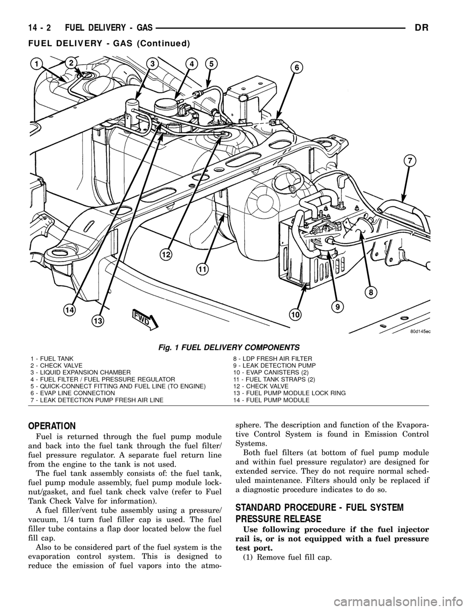
(Fig. 1).
DRFUEL SYSTEM 14 - 1
Page 1571 of 2627
OPERATION
Fuel is returned through the fuel pump module
and back into the fuel tank through the fuel filter/
fuel pressure regulator. A separate fuel return line
from the engine to the tank is not used.
The fuel tank assembly consists of: the fuel tank,
fuel pump module assembly, fuel pump module lock-
nut/gasket, and fuel tank check valve (refer to Fuel
Tank Check Valve for information).
A fuel filler/vent tube assembly using a pressure/
vacuum, 1/4 turn fuel filler cap is used. The fuel
filler tube contains a flap door located below the fuel
fill cap.
Also to be considered part of the fuel system is the
evaporation control system. This is designed to
reduce the emission of fuel vapors into the atmo-sphere. The description and function of the Evapora-
tive Control System is found in Emission Control
Systems.
Both fuel filters (at bottom of fuel pump module
and within fuel pressure regulator) are designed for
extended service. They do not require normal sched-
uled maintenance. Filters should only be replaced if
a diagnostic procedure indicates to do so.
STANDARD PROCEDURE - FUEL SYSTEM
PRESSURE RELEASE
Use following procedure if the fuel injector
rail is, or is not equipped with a fuel pressure
test port.
(1) Remove fuel fill cap.
Fig. 1 FUEL DELIVERY COMPONENTS
1 - FUEL TANK 8 - LDP FRESH AIR FILTER
2 - CHECK VALVE 9 - LEAK DETECTION PUMP
3 - LIQUID EXPANSION CHAMBER 10 - EVAP CANISTERS (2)
4 - FUEL FILTER / FUEL PRESSURE REGULATOR 11 - FUEL TANK STRAPS (2)
5 - QUICK-CONNECT FITTING AND FUEL LINE (TO ENGINE) 12 - CHECK VALVE
6 - EVAP LINE CONNECTION 13 - FUEL PUMP MODULE LOCK RING
7 - LEAK DETECTION PUMP FRESH AIR LINE 14 - FUEL PUMP MODULE
14 - 2 FUEL DELIVERY - GASDR
FUEL DELIVERY - GAS (Continued)