ASD DODGE RAM 1500 1998 2.G Owner's Manual
[x] Cancel search | Manufacturer: DODGE, Model Year: 1998, Model line: RAM 1500, Model: DODGE RAM 1500 1998 2.GPages: 2627
Page 1112 of 2627
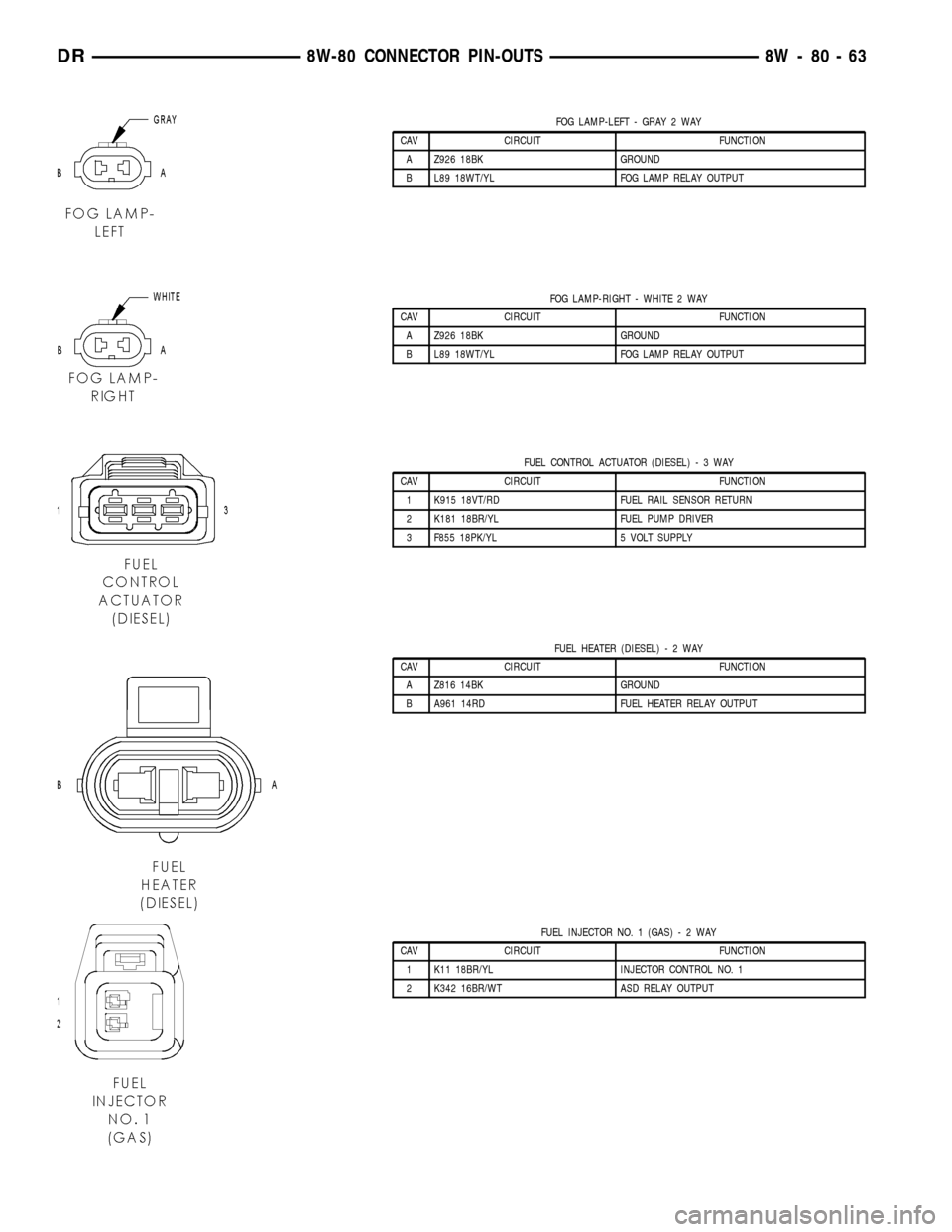
FOG LAMP-LEFT - GRAY 2 WAY
CAV CIRCUIT FUNCTION
A Z926 18BK GROUND
B L89 18WT/YL FOG LAMP RELAY OUTPUT
FOG LAMP-RIGHT - WHITE 2 WAY
CAV CIRCUIT FUNCTION
A Z926 18BK GROUND
B L89 18WT/YL FOG LAMP RELAY OUTPUT
FUEL CONTROL ACTUATOR (DIESEL)-3WAY
CAV CIRCUIT FUNCTION
1 K915 18VT/RD FUEL RAIL SENSOR RETURN
2 K181 18BR/YL FUEL PUMP DRIVER
3 F855 18PK/YL 5 VOLT SUPPLY
FUEL HEATER (DIESEL)-2WAY
CAV CIRCUIT FUNCTION
A Z816 14BK GROUND
B A961 14RD FUEL HEATER RELAY OUTPUT
FUEL INJECTOR NO. 1 (GAS)-2WAY
CAV CIRCUIT FUNCTION
1 K11 18BR/YL INJECTOR CONTROL NO. 1
2 K342 16BR/WT ASD RELAY OUTPUT
DR8W-80 CONNECTOR PIN-OUTS 8W - 80 - 63
Page 1113 of 2627
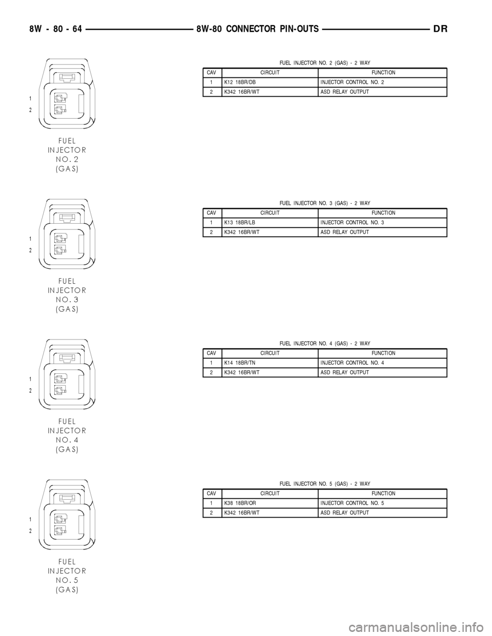
FUEL INJECTOR NO. 2 (GAS)-2WAY
CAV CIRCUIT FUNCTION
1 K12 18BR/DB INJECTOR CONTROL NO. 2
2 K342 16BR/WT ASD RELAY OUTPUT
FUEL INJECTOR NO. 3 (GAS)-2WAY
CAV CIRCUIT FUNCTION
1 K13 18BR/LB INJECTOR CONTROL NO. 3
2 K342 16BR/WT ASD RELAY OUTPUT
FUEL INJECTOR NO. 4 (GAS)-2WAY
CAV CIRCUIT FUNCTION
1 K14 18BR/TN INJECTOR CONTROL NO. 4
2 K342 16BR/WT ASD RELAY OUTPUT
FUEL INJECTOR NO. 5 (GAS)-2WAY
CAV CIRCUIT FUNCTION
1 K38 18BR/OR INJECTOR CONTROL NO. 5
2 K342 16BR/WT ASD RELAY OUTPUT
8W - 80 - 64 8W-80 CONNECTOR PIN-OUTSDR
Page 1114 of 2627
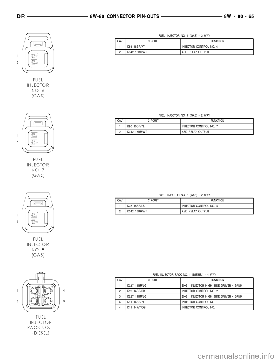
FUEL INJECTOR NO. 6 (GAS)-2WAY
CAV CIRCUIT FUNCTION
1 K58 18BR/VT INJECTOR CONTROL NO. 6
2 K342 16BR/WT ASD RELAY OUTPUT
FUEL INJECTOR NO. 7 (GAS)-2WAY
CAV CIRCUIT FUNCTION
1 K26 18BR/YL INJECTOR CONTROL NO. 7
2 K342 16BR/WT ASD RELAY OUTPUT
FUEL INJECTOR NO. 8 (GAS)-2WAY
CAV CIRCUIT FUNCTION
1 K28 18BR/LB INJECTOR CONTROL NO. 8
2 K342 16BR/WT ASD RELAY OUTPUT
FUEL INJECTOR PACK NO. 1 (DIESEL)-4WAY
CAV CIRCUIT FUNCTION
1 K227 14BR/LG ENG - INJECTOR HIGH SIDE DRIVER - BANK 1
2 K12 14BR/DB INJECTOR CONTROL NO. 2
3 K227 14BR/LG ENG - INJECTOR HIGH SIDE DRIVER - BANK 1
4 K11 14BR/YL INJECTOR CONTROL NO. 1
4 K11 14WT/DB INJECTOR CONTROL NO. 1
DR8W-80 CONNECTOR PIN-OUTS 8W - 80 - 65
Page 1125 of 2627
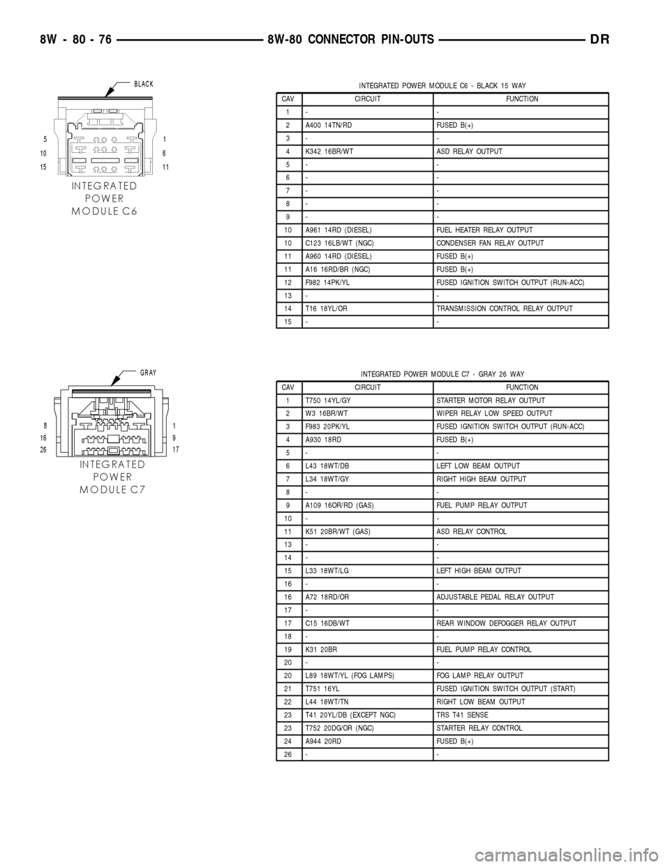
INTEGRATED POWER MODULE C6 - BLACK 15 WAY
CAV CIRCUIT FUNCTION
1- -
2 A400 14TN/RD FUSED B(+)
3- -
4 K342 16BR/WT ASD RELAY OUTPUT
5- -
6- -
7- -
8- -
9- -
10 A961 14RD (DIESEL) FUEL HEATER RELAY OUTPUT
10 C123 16LB/WT (NGC) CONDENSER FAN RELAY OUTPUT
11 A960 14RD (DIESEL) FUSED B(+)
11 A16 16RD/BR (NGC) FUSED B(+)
12 F982 14PK/YL FUSED IGNITION SWITCH OUTPUT (RUN-ACC)
13 - -
14 T16 18YL/OR TRANSMISSION CONTROL RELAY OUTPUT
15 - -
INTEGRATED POWER MODULE C7 - GRAY 26 WAY
CAV CIRCUIT FUNCTION
1 T750 14YL/GY STARTER MOTOR RELAY OUTPUT
2 W3 16BR/WT WIPER RELAY LOW SPEED OUTPUT
3 F983 20PK/YL FUSED IGNITION SWITCH OUTPUT (RUN-ACC)
4 A930 18RD FUSED B(+)
5- -
6 L43 18WT/DB LEFT LOW BEAM OUTPUT
7 L34 18WT/GY RIGHT HIGH BEAM OUTPUT
8- -
9 A109 16OR/RD (GAS) FUEL PUMP RELAY OUTPUT
10 - -
11 K51 20BR/WT (GAS) ASD RELAY CONTROL
13 - -
14 - -
15 L33 18WT/LG LEFT HIGH BEAM OUTPUT
16 - -
16 A72 18RD/OR ADJUSTABLE PEDAL RELAY OUTPUT
17 - -
17 C15 16DB/WT REAR WINDOW DEFOGGER RELAY OUTPUT
18 - -
19 K31 20BR FUEL PUMP RELAY CONTROL
20 - -
20 L89 18WT/YL (FOG LAMPS) FOG LAMP RELAY OUTPUT
21 T751 16YL FUSED IGNITION SWITCH OUTPUT (START)
22 L44 18WT/TN RIGHT LOW BEAM OUTPUT
23 T41 20YL/DB (EXCEPT NGC) TRS T41 SENSE
23 T752 20DG/OR (NGC) STARTER RELAY CONTROL
24 A944 20RD FUSED B(+)
26 - -
8W - 80 - 76 8W-80 CONNECTOR PIN-OUTSDR
Page 1139 of 2627
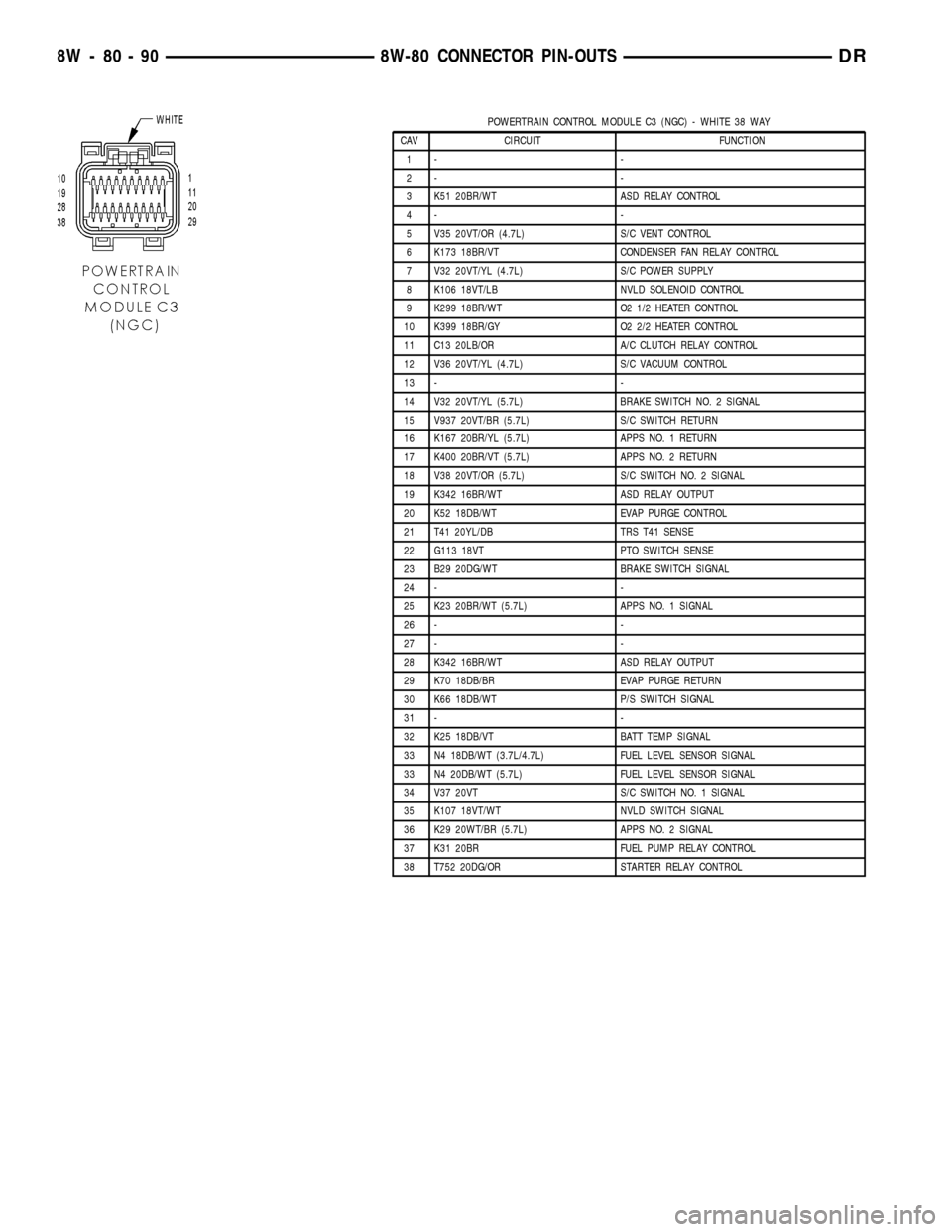
POWERTRAIN CONTROL MODULE C3 (NGC) - WHITE 38 WAY
CAV CIRCUIT FUNCTION
1- -
2- -
3 K51 20BR/WT ASD RELAY CONTROL
4- -
5 V35 20VT/OR (4.7L) S/C VENT CONTROL
6 K173 18BR/VT CONDENSER FAN RELAY CONTROL
7 V32 20VT/YL (4.7L) S/C POWER SUPPLY
8 K106 18VT/LB NVLD SOLENOID CONTROL
9 K299 18BR/WT O2 1/2 HEATER CONTROL
10 K399 18BR/GY O2 2/2 HEATER CONTROL
11 C13 20LB/OR A/C CLUTCH RELAY CONTROL
12 V36 20VT/YL (4.7L) S/C VACUUM CONTROL
13 - -
14 V32 20VT/YL (5.7L) BRAKE SWITCH NO. 2 SIGNAL
15 V937 20VT/BR (5.7L) S/C SWITCH RETURN
16 K167 20BR/YL (5.7L) APPS NO. 1 RETURN
17 K400 20BR/VT (5.7L) APPS NO. 2 RETURN
18 V38 20VT/OR (5.7L) S/C SWITCH NO. 2 SIGNAL
19 K342 16BR/WT ASD RELAY OUTPUT
20 K52 18DB/WT EVAP PURGE CONTROL
21 T41 20YL/DB TRS T41 SENSE
22 G113 18VT PTO SWITCH SENSE
23 B29 20DG/WT BRAKE SWITCH SIGNAL
24 - -
25 K23 20BR/WT (5.7L) APPS NO. 1 SIGNAL
26 - -
27 - -
28 K342 16BR/WT ASD RELAY OUTPUT
29 K70 18DB/BR EVAP PURGE RETURN
30 K66 18DB/WT P/S SWITCH SIGNAL
31 - -
32 K25 18DB/VT BATT TEMP SIGNAL
33 N4 18DB/WT (3.7L/4.7L) FUEL LEVEL SENSOR SIGNAL
33 N4 20DB/WT (5.7L) FUEL LEVEL SENSOR SIGNAL
34 V37 20VT S/C SWITCH NO. 1 SIGNAL
35 K107 18VT/WT NVLD SWITCH SIGNAL
36 K29 20WT/BR (5.7L) APPS NO. 2 SIGNAL
37 K31 20BR FUEL PUMP RELAY CONTROL
38 T752 20DG/OR STARTER RELAY CONTROL
8W - 80 - 90 8W-80 CONNECTOR PIN-OUTSDR
Page 1231 of 2627
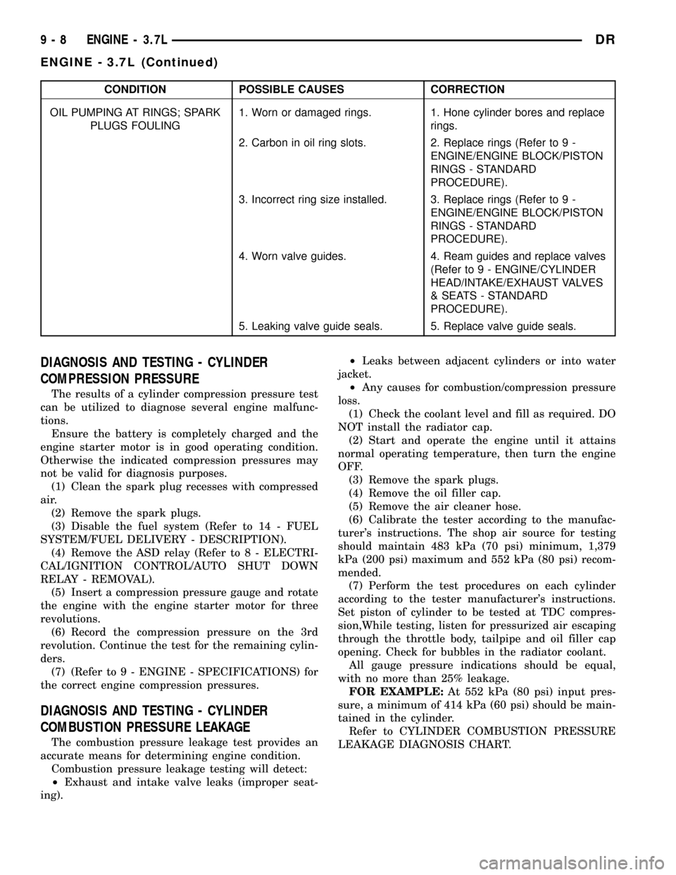
CONDITION POSSIBLE CAUSES CORRECTION
OIL PUMPING AT RINGS; SPARK
PLUGS FOULING1. Worn or damaged rings. 1. Hone cylinder bores and replace
rings.
2. Carbon in oil ring slots. 2. Replace rings (Refer to 9 -
ENGINE/ENGINE BLOCK/PISTON
RINGS - STANDARD
PROCEDURE).
3. Incorrect ring size installed. 3. Replace rings (Refer to 9 -
ENGINE/ENGINE BLOCK/PISTON
RINGS - STANDARD
PROCEDURE).
4. Worn valve guides. 4. Ream guides and replace valves
(Refer to 9 - ENGINE/CYLINDER
HEAD/INTAKE/EXHAUST VALVES
& SEATS - STANDARD
PROCEDURE).
5. Leaking valve guide seals. 5. Replace valve guide seals.
DIAGNOSIS AND TESTING - CYLINDER
COMPRESSION PRESSURE
The results of a cylinder compression pressure test
can be utilized to diagnose several engine malfunc-
tions.
Ensure the battery is completely charged and the
engine starter motor is in good operating condition.
Otherwise the indicated compression pressures may
not be valid for diagnosis purposes.
(1) Clean the spark plug recesses with compressed
air.
(2) Remove the spark plugs.
(3) Disable the fuel system (Refer to 14 - FUEL
SYSTEM/FUEL DELIVERY - DESCRIPTION).
(4) Remove the ASD relay (Refer to 8 - ELECTRI-
CAL/IGNITION CONTROL/AUTO SHUT DOWN
RELAY - REMOVAL).
(5) Insert a compression pressure gauge and rotate
the engine with the engine starter motor for three
revolutions.
(6) Record the compression pressure on the 3rd
revolution. Continue the test for the remaining cylin-
ders.
(7) (Refer to 9 - ENGINE - SPECIFICATIONS) for
the correct engine compression pressures.
DIAGNOSIS AND TESTING - CYLINDER
COMBUSTION PRESSURE LEAKAGE
The combustion pressure leakage test provides an
accurate means for determining engine condition.
Combustion pressure leakage testing will detect:
²Exhaust and intake valve leaks (improper seat-
ing).²Leaks between adjacent cylinders or into water
jacket.
²Any causes for combustion/compression pressure
loss.
(1) Check the coolant level and fill as required. DO
NOT install the radiator cap.
(2) Start and operate the engine until it attains
normal operating temperature, then turn the engine
OFF.
(3) Remove the spark plugs.
(4) Remove the oil filler cap.
(5) Remove the air cleaner hose.
(6) Calibrate the tester according to the manufac-
turer's instructions. The shop air source for testing
should maintain 483 kPa (70 psi) minimum, 1,379
kPa (200 psi) maximum and 552 kPa (80 psi) recom-
mended.
(7) Perform the test procedures on each cylinder
according to the tester manufacturer's instructions.
Set piston of cylinder to be tested at TDC compres-
sion,While testing, listen for pressurized air escaping
through the throttle body, tailpipe and oil filler cap
opening. Check for bubbles in the radiator coolant.
All gauge pressure indications should be equal,
with no more than 25% leakage.
FOR EXAMPLE:At 552 kPa (80 psi) input pres-
sure, a minimum of 414 kPa (60 psi) should be main-
tained in the cylinder.
Refer to CYLINDER COMBUSTION PRESSURE
LEAKAGE DIAGNOSIS CHART.
9 - 8 ENGINE - 3.7LDR
ENGINE - 3.7L (Continued)
Page 1316 of 2627
DIAGNOSIS AND TESTING - CYLINDER
COMPRESSION PRESSURE
The results of a cylinder compression pressure test
can be utilized to diagnose several engine malfunc-
tions.
Ensure the battery is completely charged and the
engine starter motor is in good operating condition.
Otherwise the indicated compression pressures may
not be valid for diagnosis purposes.
(1) Clean the spark plug recesses with compressed
air.
(2) Remove the spark plugs.
(3) Disable the fuel system (Refer to 14 - FUEL
SYSTEM/FUEL DELIVERY - DESCRIPTION).
(4) Remove the ASD relay (Refer to 8 - ELECTRI-
CAL/IGNITION CONTROL/AUTO SHUT DOWN
RELAY - REMOVAL).
(5) Insert a compression pressure gauge and rotate
the engine with the engine starter motor for three
revolutions.
(6)
Record the compression pressure on the 3rd revo-
lution. Continue the test for the remaining cylinders.
(7) (Refer to 9 - ENGINE - SPECIFICATIONS) for
the correct engine compression pressures.
DIAGNOSIS AND TESTING - CYLINDER
COMBUSTION PRESSURE LEAKAGE
The combustion pressure leakage test provides an
accurate means for determining engine condition.
Combustion pressure leakage testing will detect:
²
Exhaust and intake valve leaks (improper seating).
²Leaks between adjacent cylinders or into water
jacket.
²Any causes for combustion/compression pressure
loss.
(1) Check the coolant level and fill as required. DO
NOT install the radiator cap.
(2) Start and operate the engine until it attains
normal operating temperature, then turn the engine
OFF.
(3) Remove the spark plugs.
(4) Remove the oil filler cap.
(5) Remove the air cleaner hose.
(6) Calibrate the tester according to the manufac-
turer's instructions. The shop air source for testing
should maintain 483 kPa (70 psi) minimum, 1,379
kPa (200 psi) maximum and 552 kPa (80 psi) recom-
mended.
(7) Perform the test procedures on each cylinder
according to the tester manufacturer's instructions.
Set piston of cylinder to be tested at TDC compres-
sion,While testing, listen for pressurized air escaping
through the throttle body, tailpipe and oil filler cap
opening. Check for bubbles in the radiator coolant.
All gauge pressure indications should be equal,
with no more than 25% leakage.
FOR EXAMPLE:At 552 kPa (80 psi) input pres-
sure, a minimum of 414 kPa (60 psi) should be main-
tained in the cylinder.
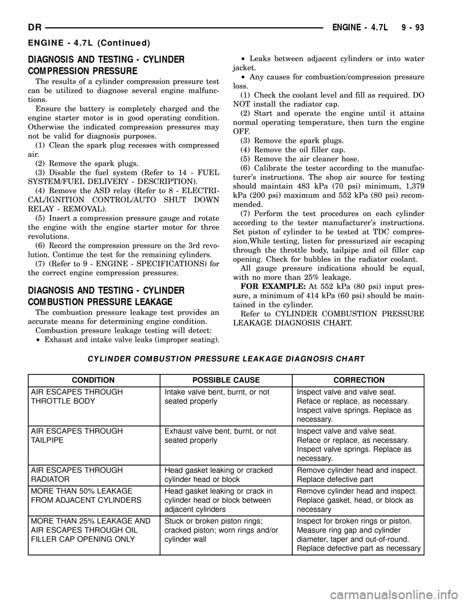
Refer to CYLINDER COMBUSTION PRESSURE
LEAKAGE DIAGNOSIS CHART.
CYLINDER COMBUSTION PRESSURE LEAKAGE DIAGNOSIS CHART
CONDITION POSSIBLE CAUSE CORRECTION
AIR ESCAPES THROUGH
THROTTLE BODYIntake valve bent, burnt, or not
seated properlyInspect valve and valve seat.
Reface or replace, as necessary.
Inspect valve springs. Replace as
necessary.
AIR ESCAPES THROUGH
TAILPIPEExhaust valve bent, burnt, or not
seated properlyInspect valve and valve seat.
Reface or replace, as necessary.
Inspect valve springs. Replace as
necessary.
AIR ESCAPES THROUGH
RADIATORHead gasket leaking or cracked
cylinder head or blockRemove cylinder head and inspect.
Replace defective part
MORE THAN 50% LEAKAGE
FROM ADJACENT CYLINDERSHead gasket leaking or crack in
cylinder head or block between
adjacent cylindersRemove cylinder head and inspect.
Replace gasket, head, or block as
necessary
MORE THAN 25% LEAKAGE AND
AIR ESCAPES THROUGH OIL
FILLER CAP OPENING ONLYStuck or broken piston rings;
cracked piston; worn rings and/or
cylinder wallInspect for broken rings or piston.
Measure ring gap and cylinder
diameter, taper and out-of-round.
Replace defective part as necessary
DRENGINE - 4.7L 9 - 93
ENGINE - 4.7L (Continued)
Page 1409 of 2627
DIAGNOSIS AND TESTING - CYLINDER
COMPRESSION PRESSURE
The results of a cylinder compression pressure test
can be utilized to diagnose several engine malfunc-
tions.
Ensure the battery is completely charged and the
engine starter motor is in good operating condition.
Otherwise the indicated compression pressures may
not be valid for diagnosis purposes.
(1) Clean the spark plug recesses with compressed
air.
(2) Remove the spark plugs.
(3) Disable the fuel system (Refer to 14 - FUEL
SYSTEM/FUEL DELIVERY - DESCRIPTION).
(4) Remove the ASD relay (Refer to 8 - ELECTRI-
CAL/IGNITION CONTROL/AUTO SHUT DOWN
RELAY - REMOVAL).
(5) Insert a compression pressure gauge and rotate
the engine with the engine starter motor for three
revolutions.
(6) Record the compression pressure on the 3rd
revolution. Continue the test for the remaining cylin-
ders.
(7) (Refer to 9 - ENGINE - SPECIFICATIONS) for
the correct engine compression pressures.
DIAGNOSIS AND TESTING - CYLINDER
COMBUSTION PRESSURE LEAKAGE
The combustion pressure leakage test provides an
accurate means for determining engine condition.
Combustion pressure leakage testing will detect:
²Exhaust and intake valve leaks (improper seat-
ing).²Leaks between adjacent cylinders or into water
jacket.
²Any causes for combustion/compression pressure
loss.
(1) Check the coolant level and fill as required. DO
NOT install the radiator cap.
(2) Start and operate the engine until it attains
normal operating temperature, then turn the engine
OFF.
(3) Remove the spark plugs.
(4) Remove the oil filler cap.
(5) Remove the air cleaner hose.
(6) Calibrate the tester according to the manufac-
turer's instructions. The shop air source for testing
should maintain 483 kPa (70 psi) minimum, 1,379
kPa (200 psi) maximum and 552 kPa (80 psi) recom-
mended.
(7) Perform the test procedures on each cylinder
according to the tester manufacturer's instructions.
Set piston of cylinder to be tested at TDC compres-
sion,While testing, listen for pressurized air escaping
through the throttle body, tailpipe and oil filler cap
opening. Check for bubbles in the radiator coolant.
All gauge pressure indications should be equal,
with no more than 25% leakage.
FOR EXAMPLE:At 552 kPa (80 psi) input pres-
sure, a minimum of 414 kPa (60 psi) should be main-
tained in the cylinder.
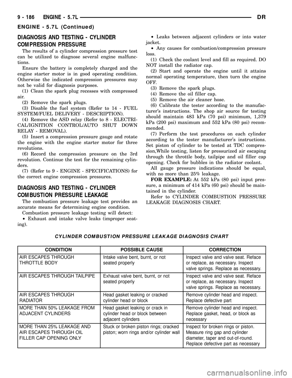
Refer to CYLINDER COMBUSTION PRESSURE
LEAKAGE DIAGNOSIS CHART.
CYLINDER COMBUSTION PRESSURE LEAKAGE DIAGNOSIS CHART
CONDITION POSSIBLE CAUSE CORRECTION
AIR ESCAPES THROUGH
THROTTLE BODYIntake valve bent, burnt, or not
seated properlyInspect valve and valve seat. Reface
or replace, as necessary. Inspect
valve springs. Replace as necessary.
AIR ESCAPES THROUGH TAILPIPE Exhaust valve bent, burnt, or not
seated properlyInspect valve and valve seat. Reface
or replace, as necessary. Inspect
valve springs. Replace as necessary.
AIR ESCAPES THROUGH
RADIATORHead gasket leaking or cracked
cylinder head or blockRemove cylinder head and inspect.
Replace defective part
MORE THAN 50% LEAKAGE FROM
ADJACENT CYLINDERSHead gasket leaking or crack in
cylinder head or block between
adjacent cylindersRemove cylinder head and inspect.
Replace gasket, head, or block as
necessary
MORE THAN 25% LEAKAGE AND
AIR ESCAPES THROUGH OIL
FILLER CAP OPENING ONLYStuck or broken piston rings; cracked
piston; worn rings and/or cylinder wallInspect for broken rings or piston.
Measure ring gap and cylinder
diameter, taper and out-of-round.
Replace defective part as necessary
9 - 186 ENGINE - 5.7LDR
ENGINE - 5.7L (Continued)
Page 1571 of 2627
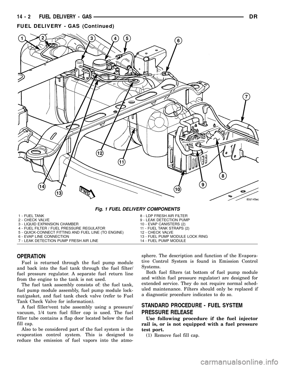
OPERATION
Fuel is returned through the fuel pump module
and back into the fuel tank through the fuel filter/
fuel pressure regulator. A separate fuel return line
from the engine to the tank is not used.
The fuel tank assembly consists of: the fuel tank,
fuel pump module assembly, fuel pump module lock-
nut/gasket, and fuel tank check valve (refer to Fuel
Tank Check Valve for information).
A fuel filler/vent tube assembly using a pressure/
vacuum, 1/4 turn fuel filler cap is used. The fuel
filler tube contains a flap door located below the fuel
fill cap.
Also to be considered part of the fuel system is the
evaporation control system. This is designed to
reduce the emission of fuel vapors into the atmo-sphere. The description and function of the Evapora-
tive Control System is found in Emission Control
Systems.
Both fuel filters (at bottom of fuel pump module
and within fuel pressure regulator) are designed for
extended service. They do not require normal sched-
uled maintenance. Filters should only be replaced if
a diagnostic procedure indicates to do so.
STANDARD PROCEDURE - FUEL SYSTEM
PRESSURE RELEASE
Use following procedure if the fuel injector
rail is, or is not equipped with a fuel pressure
test port.
(1) Remove fuel fill cap.
Fig. 1 FUEL DELIVERY COMPONENTS
1 - FUEL TANK 8 - LDP FRESH AIR FILTER
2 - CHECK VALVE 9 - LEAK DETECTION PUMP
3 - LIQUID EXPANSION CHAMBER 10 - EVAP CANISTERS (2)
4 - FUEL FILTER / FUEL PRESSURE REGULATOR 11 - FUEL TANK STRAPS (2)
5 - QUICK-CONNECT FITTING AND FUEL LINE (TO ENGINE) 12 - CHECK VALVE
6 - EVAP LINE CONNECTION 13 - FUEL PUMP MODULE LOCK RING
7 - LEAK DETECTION PUMP FRESH AIR LINE 14 - FUEL PUMP MODULE
14 - 2 FUEL DELIVERY - GASDR
FUEL DELIVERY - GAS (Continued)
Page 1573 of 2627
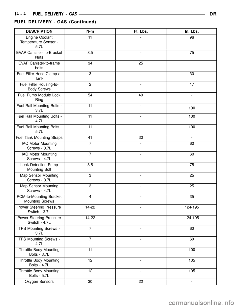
DESCRIPTION N-m Ft. Lbs. In. Lbs.
Engine Coolant
Temperature Sensor -
5.7L11 - 9 6
EVAP Canister- to-Bracket
Nuts8.5 - 75
EVAP Canister-to-frame
bolts34 25
Fuel Filler Hose Clamp at
Tank3-30
Fuel Filler Housing-to-
Body Screws2-17
Fuel Pump Module Lock
Ring54 40 -
Fuel Rail Mounting Bolts -
3.7L11 -
100
Fuel Rail Mounting Bolts -
4.7L11 - 100
Fuel Rail Mounting Bolts -
5.7L11 - 100
Fuel Tank Mounting Straps 41 30 -
IAC Motor Mounting
Screws - 3.7L7-60
IAC Motor Mounting
Screws - 4.7L7-60
Leak Detection Pump
Mounting Bolt8.5 - 75
Map Sensor Mounting
Screws - 3.7L3-25
Map Sensor Mounting
Screws - 4.7L3-25
PCM-to-Mounting Bracket
Mounting Screws4-35
Power Steering Pressure
Switch - 3.7L14-22 - 124-195
Power Steering Pressure
Switch - 4.7L14-22 - 124-195
TPS Mounting Screws -
3.7L7-60
TPS Mounting Screws -
4.7L7-60
Throttle Body Mounting
Bolts - 3.7L11 - 100
Throttle Body Mounting
Bolts - 4.7L12 - 105
Throttle Body Mounting
Bolts - 5.7L12 - 105
Oxygen Sensors 30 22 -
14 - 4 FUEL DELIVERY - GASDR
FUEL DELIVERY - GAS (Continued)