Timing DODGE RAM 1500 1998 2.G Owner's Guide
[x] Cancel search | Manufacturer: DODGE, Model Year: 1998, Model line: RAM 1500, Model: DODGE RAM 1500 1998 2.GPages: 2627
Page 502 of 2627

Knock sensors contain a piezoelectric material
which constantly vibrates and sends an input voltage
(signal) to the PCM while the engine operates. As the
intensity of the crystal's vibration increases, the
knock sensor output voltage also increases.
The voltage signal produced by the knock sensor
increases with the amplitude of vibration. The PCM
receives the knock sensor voltage signal as an input.
If the signal rises above a predetermined level, the
PCM will store that value in memory and retard
ignition timing to reduce engine knock. If the knock
sensor voltage exceeds a preset value, the PCM
retards ignition timing for all cylinders. It is not a
selective cylinder retard.
The PCM ignores knock sensor input during engine
idle conditions. Once the engine speed exceeds a
specified value, knock retard is allowed.
Knock retard uses its own short term and long
term memory program.
Long term memory stores previous detonation
information in its battery-backed RAM. The maxi-
mum authority that long term memory has over tim-
ing retard can be calibrated.
Short term memory is allowed to retard timing up
to a preset amount under all operating conditions (as
long as rpm is above the minimum rpm) except at
Wide Open Throttle (WOT). The PCM, using short
term memory, can respond quickly to retard timing
when engine knock is detected. Short term memory
is lost any time the ignition key is turned off.
NOTE: Over or under tightening the sensor mount-
ing bolts will affect knock sensor performance, pos-
sibly causing improper spark control. Always use
the specified torque when installing the knock sen-
sors.
REMOVAL
3.7L V-6 / 4.7L V-8
The 2 knock sensors are bolted into the cylinder
block under the intake manifold (Fig. 20). or (Fig.
21).
NOTE: The left sensor is identified by an identifica-
tion tag (LEFT). It is also identified by a larger bolt
head. The Powertrain Control Module (PCM) must
have and know the correct sensor left/right posi-
tions. Do not mix the sensor locations.
(1) Disconnect knock sensor dual pigtail harness
from engine wiring harness. This connection is made
near rear of engine.
(2) Remove intake manifold. Refer to Engine sec-
tion.(3) Remove sensor mounting bolts (Fig. 20), or
(Fig. 21). Note foam strip on bolt threads. This foam
is used only to retain the bolts to sensors for plant
assembly. It is not used as a sealant. Do not apply
any adhesive, sealant or thread locking compound to
these bolts.
(4) Remove sensors from engine.
5.7L V8
Two sensors are used. Each sensor is bolted into
the outside of cylinder block below the exhaust man-
ifold (Fig. 22).
(1) Raise vehicle.
(2) Disconnect knock sensor electrical connector.
(3) Remove sensor mounting bolt (Fig. 22). Note
foam strip on bolt threads. This foam is used only to
retain the bolts to sensors for plant assembly. It is
not used as a sealant. Do not apply any adhesive,
sealant or thread locking compound to these bolts.
(4) Remove sensor from engine.
INSTALLATION
3.7L V-6 / 4.7L V-8
NOTE: The left sensor is identified by an identifica-
tion tag (LEFT). It is also identified by a larger bolt
head. The Powertrain Control Module (PCM) must
have and know the correct sensor left/right posi-
tions. Do not mix the sensor locations.
Fig. 20 KNOCK SENSOR Ð 3.7L V-6
1 - KNOCK SENSORS (2)
2 - MOUNTING BOLTS
DRIGNITION CONTROL 8I - 15
KNOCK SENSOR (Continued)
Page 505 of 2627

ELECTRODE GAP BRIDGING
Electrode gap bridging may be traced to loose
deposits in the combustion chamber. These deposits
accumulate on the spark plugs during continuous
stop-and-go driving. When the engine is suddenly
subjected to a high torque load, deposits partially liq-
uefy and bridge the gap between electrodes (Fig. 25).
This short circuits the electrodes. Spark plugs with
electrode gap bridging can be cleaned using standard
procedures.
SCAVENGER DEPOSITS
Fuel scavenger deposits may be either white or yel-
low (Fig. 26). They may appear to be harmful, but
this is a normal condition caused by chemical addi-
tives in certain fuels. These additives are designed to
change the chemical nature of deposits and decrease
spark plug misfire tendencies. Notice that accumula-
tion on the ground electrode and shell area may be
heavy, but the deposits are easily removed. Spark
plugs with scavenger deposits can be considered nor-
mal in condition and can be cleaned using standard
procedures.
CHIPPED ELECTRODE INSULATOR
A chipped electrode insulator usually results from
bending the center electrode while adjusting the
spark plug electrode gap. Under certain conditions,
severe detonation can also separate the insulator
from the center electrode (Fig. 27). Spark plugs with
this condition must be replaced.
PREIGNITION DAMAGE
Preignition damage is usually caused by excessive
combustion chamber temperature. The center elec-
trode dissolves first and the ground electrode dis-
solves somewhat latter (Fig. 28). Insulators appear
relatively deposit free. Determine if the spark plug
has the correct heat range rating for the engine.
Determine if ignition timing is over advanced or if
other operating conditions are causing engine over-
heating. (The heat range rating refers to the operat-
ing temperature of a particular type spark plug.
Spark plugs are designed to operate within specific
temperature ranges. This depends upon the thick-
ness and length of the center electrodes porcelain
insulator.)
Fig. 24 OIL OR ASH ENCRUSTED
Fig. 25 ELECTRODE GAP BRIDGING
1 - GROUND ELECTRODE
2 - DEPOSITS
3 - CENTER ELECTRODE
Fig. 26 SCAVENGER DEPOSITS
1 - GROUND ELECTRODE COVERED WITH WHITE OR YELLOW
DEPOSITS
2 - CENTER ELECTRODE
8I - 18 IGNITION CONTROLDR
SPARK PLUG (Continued)
Page 506 of 2627

SPARK PLUG OVERHEATING
Overheating is indicated by a white or gray center
electrode insulator that also appears blistered (Fig.
29). The increase in electrode gap will be consider-
ably in excess of 0.001 inch per 2000 miles of opera-
tion. This suggests that a plug with a cooler heat
range rating should be used. Over advanced ignition
timing, detonation and cooling system malfunctions
can also cause spark plug overheating.
REMOVAL
3.7L V-6
Each individual spark plug is located under each
ignition coil. Each individual ignition coil must be
removed to gain access to each spark plug. Refer to
Ignition Coil Removal/Installation.(1) Remove necessary air filter tubing at throttle
body.
(2) Prior to removing ignition coil, spray com-
pressed air around coil base at cylinder head.
(3) Prior to removing spark plug, spray com-
pressed air into cylinder head opening. This will help
prevent foreign material from entering combustion
chamber.
(4) Remove spark plug from cylinder head using a
quality socket with a rubber or foam insert. Also
check condition of ignition coil o-ring and replace as
necessary.
(5) Inspect spark plug condition. Refer to Diagnos-
tics and Testing - Spark Plug Conditions.
4.7L V-8
Each individual spark plug is located under each
ignition coil. Each individual ignition coil must be
removed to gain access to each spark plug. Refer to
Ignition Coil Removal/Installation.
(1) Remove necessary air filter tubing at throttle
body.
(2) Prior to removing ignition coil, spray com-
pressed air around coil base at cylinder head.
(3) Prior to removing spark plug, spray com-
pressed air into cylinder head opening. This will help
prevent foreign material from entering combustion
chamber.
(4) Remove spark plug from cylinder head using a
quality socket with a rubber or foam insert. Also
check condition of ignition coil o-ring and replace as
necessary.
(5) Inspect spark plug condition. Refer to Diagnos-
tics and Testing - Spark Plug Conditions.
5.7L V-8
Eight of the 16 spark plugs are located under an
ignition coil; the other 8 are not. If spark plug being
Fig. 27 CHIPPED ELECTRODE INSULATOR
1 - GROUND ELECTRODE
2 - CENTER ELECTRODE
3 - CHIPPED INSULATOR
Fig. 28 PREIGNITION DAMAGE
1 - GROUND ELECTRODE STARTING TO DISSOLVE
2 - CENTER ELECTRODE DISSOLVED
Fig. 29 SPARK PLUG OVERHEATING
1 - BLISTERED WHITE OR GRAY COLORED INSULATOR
DRIGNITION CONTROL 8I - 19
SPARK PLUG (Continued)
Page 1225 of 2627

REMOVAL.............................38
INSTALLATION.........................38
ENGINE BLOCK
DESCRIPTION.........................38
STANDARD PROCEDURE - CYLINDER BORE
HONING............................38
CLEANING............................39
INSPECTION..........................39
CRANKSHAFT
DESCRIPTION.........................40
REMOVAL.............................40
INSPECTION..........................41
INSTALLATION.........................42
CRANKSHAFT MAIN BEARINGS
STANDARD PROCEDURE
MAIN BEARING FITTING................44
CRANKSHAFT OIL SEAL - FRONT
REMOVAL.............................46
INSTALLATION.........................46
CRANKSHAFT OIL SEAL - REAR
REMOVAL.............................47
INSTALLATION.........................47
FLEX PLATE
REMOVAL.............................48
INSTALLATION.........................48
PISTON & CONNECTING ROD
DESCRIPTION.........................48
STANDARD PROCEDURE
CONNECTING ROD BEARING FITTING....49
STANDARD PROCEDURE - PISTON FITTING..51
REMOVAL.............................51
CLEANING............................52
INSPECTION..........................52
INSTALLATION.........................52
PISTON RINGS
STANDARD PROCEDURE - PISTON RING
FITTING.............................53
VIBRATION DAMPER
REMOVAL.............................55
INSTALLATION.........................56
STRUCTURAL COVER
DESCRIPTION.........................57
OPERATION...........................57
REMOVAL.............................57
INSTALLATION.........................57
FRONT MOUNT
REMOVAL.............................58
INSTALLATION.........................59
REAR MOUNT
REMOVAL.............................61
INSTALLATION.........................61
LUBRICATION
DESCRIPTION.........................61
OPERATION...........................61
DIAGNOSIS AND TESTING
DIAGNOSIS AND TESTING - ENGINE OIL
LEAK...............................64DIAGNOSIS AND TESTING - CHECKING
ENGINE OIL PRESSURE................65
DIAGNOSIS AND TESTING - REAR SEAL
AREA LEAKS.........................65
OIL PAN
DESCRIPTION.........................66
REMOVAL.............................66
CLEANING............................66
INSPECTION..........................66
INSTALLATION.........................66
OIL PRESSURE SENSOR/SWITCH
DESCRIPTION.........................67
OPERATION...........................67
REMOVAL.............................67
INSTALLATION.........................67
OIL PUMP
REMOVAL.............................67
DISASSEMBLY.........................68
INSPECTION..........................68
ASSEMBLY............................69
INSTALLATION.........................69
OIL FILTER
REMOVAL.............................70
INSTALLATION.........................70
OIL
STANDARD PROCEDURE - ENGINE OIL
SERVICE............................71
INTAKE MANIFOLD
DESCRIPTION.........................72
DIAGNOSIS AND TESTING - INTAKE
MANIFOLD LEAKS.....................72
REMOVAL.............................73
INSTALLATION.........................73
EXHAUST MANIFOLD
DESCRIPTION.........................74
REMOVAL.............................74
INSTALLATION.........................74
VALVE TIMING
DESCRIPTION.........................76
OPERATION...........................76
STANDARD PROCEDURE
MEASURING TIMING CHAIN WEAR.......77
SERVICE PROCEDURE - TIMING
VERIFICATION........................77
BALANCE SHAFT
REMOVAL.............................80
INSTALLATION.........................80
IDLER SHAFT
REMOVAL.............................81
INSTALLATION.........................81
TIMING BELT / CHAIN COVER(S)
REMOVAL.............................81
INSTALLATION.........................81
TIMING BELT/CHAIN AND SPROCKETS
REMOVAL.............................83
INSPECTION..........................84
INSTALLATION.........................85
9 - 2 ENGINE - 3.7LDR
Page 1227 of 2627
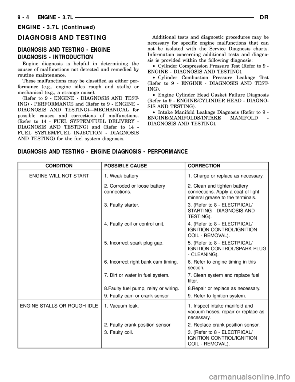
DIAGNOSIS AND TESTING
DIAGNOSIS AND TESTING - ENGINE
DIAGNOSIS - INTRODUCTION
Engine diagnosis is helpful in determining the
causes of malfunctions not detected and remedied by
routine maintenance.
These malfunctions may be classified as either per-
formance (e.g., engine idles rough and stalls) or
mechanical (e.g., a strange noise).
(Refer to 9 - ENGINE - DIAGNOSIS AND TEST-
ING) - PERFORMANCE and (Refer to 9 - ENGINE -
DIAGNOSIS AND TESTING)ÐMECHANICAL for
possible causes and corrections of malfunctions.
(Refer to 14 - FUEL SYSTEM/FUEL DELIVERY -
DIAGNOSIS AND TESTING) and (Refer to 14 -
FUEL SYSTEM/FUEL INJECTION - DIAGNOSIS
AND TESTING) for the fuel system diagnosis.Additional tests and diagnostic procedures may be
necessary for specific engine malfunctions that can
not be isolated with the Service Diagnosis charts.
Information concerning additional tests and diagno-
sis is provided within the following diagnosis:
²Cylinder Compression Pressure Test (Refer to 9 -
ENGINE - DIAGNOSIS AND TESTING).
²Cylinder Combustion Pressure Leakage Test
(Refer to 9 - ENGINE - DIAGNOSIS AND TEST-
ING).
²Engine Cylinder Head Gasket Failure Diagnosis
(Refer to 9 - ENGINE/CYLINDER HEAD - DIAGNO-
SIS AND TESTING).
²Intake Manifold Leakage Diagnosis (Refer to 9 -
ENGINE/MANIFOLDS/INTAKE MANIFOLD -
DIAGNOSIS AND TESTING).
DIAGNOSIS AND TESTING - ENGINE DIAGNOSIS - PERFORMANCE
CONDITION POSSIBLE CAUSE CORRECTION
ENGINE WILL NOT START 1. Weak battery 1. Charge or replace as necessary.
2. Corroded or loose battery
connections.2. Clean and tighten battery
connections. Apply a coat of light
mineral grease to the terminals.
3. Faulty starter. 3. (Refer to 8 - ELECTRICAL/
STARTING - DIAGNOSIS AND
TESTING).
4. Faulty coil or control unit. 4. (Refer to 8 - ELECTRICAL/
IGNITION CONTROL/IGNITION
COIL - REMOVAL).
5. Incorrect spark plug gap. 5. (Refer to 8 - ELECTRICAL/
IGNITION CONTROL/SPARK PLUG
- CLEANING).
6. Incorrect right bank cam timing. 6. Refer to engine timing in this
section.
7. Dirt or water in fuel system. 7. Clean system and replace fuel
filter.
8.Faulty fuel pump, relay or wiring. 8.Repair or replace as necessary.
9. Faulty cam or crank sensor 9. Refer to Ignition system.
ENGINE STALLS OR ROUGH IDLE 1. Vacuum leak. 1. Inspect intake manifold and
vacuum hoses, repair or replace as
necessary.
2. Faulty crank position sensor 2. Replace crank position sensor.
3. Faulty coil. 3. (Refer to 8 - ELECTRICAL/
IGNITION CONTROL/IGNITION
COIL - REMOVAL).
9 - 4 ENGINE - 3.7LDR
ENGINE - 3.7L (Continued)
Page 1228 of 2627
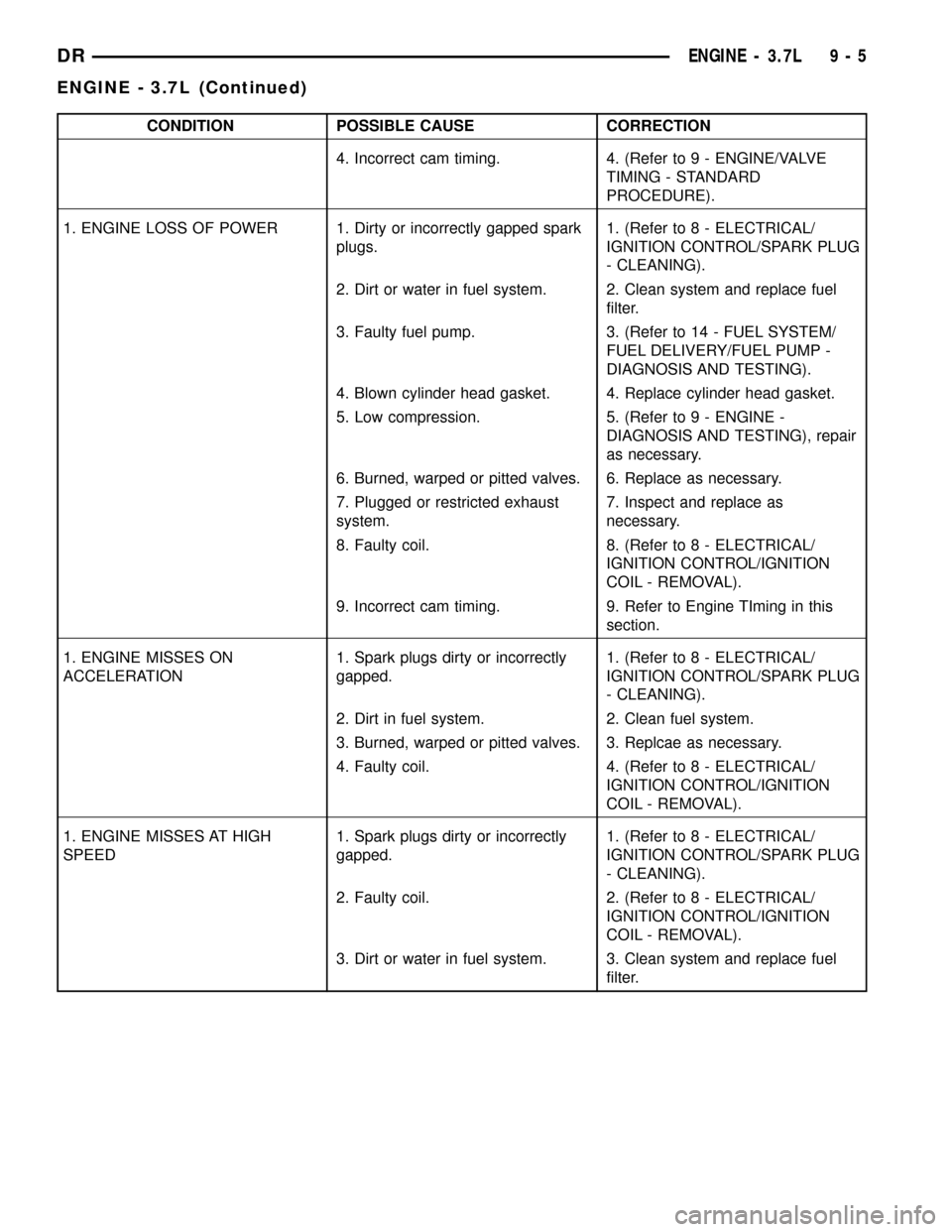
CONDITION POSSIBLE CAUSE CORRECTION
4. Incorrect cam timing. 4. (Refer to 9 - ENGINE/VALVE
TIMING - STANDARD
PROCEDURE).
1. ENGINE LOSS OF POWER 1. Dirty or incorrectly gapped spark
plugs.1. (Refer to 8 - ELECTRICAL/
IGNITION CONTROL/SPARK PLUG
- CLEANING).
2. Dirt or water in fuel system. 2. Clean system and replace fuel
filter.
3. Faulty fuel pump. 3. (Refer to 14 - FUEL SYSTEM/
FUEL DELIVERY/FUEL PUMP -
DIAGNOSIS AND TESTING).
4. Blown cylinder head gasket. 4. Replace cylinder head gasket.
5. Low compression. 5. (Refer to 9 - ENGINE -
DIAGNOSIS AND TESTING), repair
as necessary.
6. Burned, warped or pitted valves. 6. Replace as necessary.
7. Plugged or restricted exhaust
system.7. Inspect and replace as
necessary.
8. Faulty coil. 8. (Refer to 8 - ELECTRICAL/
IGNITION CONTROL/IGNITION
COIL - REMOVAL).
9. Incorrect cam timing. 9. Refer to Engine TIming in this
section.
1. ENGINE MISSES ON
ACCELERATION1. Spark plugs dirty or incorrectly
gapped.1. (Refer to 8 - ELECTRICAL/
IGNITION CONTROL/SPARK PLUG
- CLEANING).
2. Dirt in fuel system. 2. Clean fuel system.
3. Burned, warped or pitted valves. 3. Replcae as necessary.
4. Faulty coil. 4. (Refer to 8 - ELECTRICAL/
IGNITION CONTROL/IGNITION
COIL - REMOVAL).
1. ENGINE MISSES AT HIGH
SPEED1. Spark plugs dirty or incorrectly
gapped.1. (Refer to 8 - ELECTRICAL/
IGNITION CONTROL/SPARK PLUG
- CLEANING).
2. Faulty coil. 2. (Refer to 8 - ELECTRICAL/
IGNITION CONTROL/IGNITION
COIL - REMOVAL).
3. Dirt or water in fuel system. 3. Clean system and replace fuel
filter.
DRENGINE - 3.7L 9 - 5
ENGINE - 3.7L (Continued)
Page 1230 of 2627
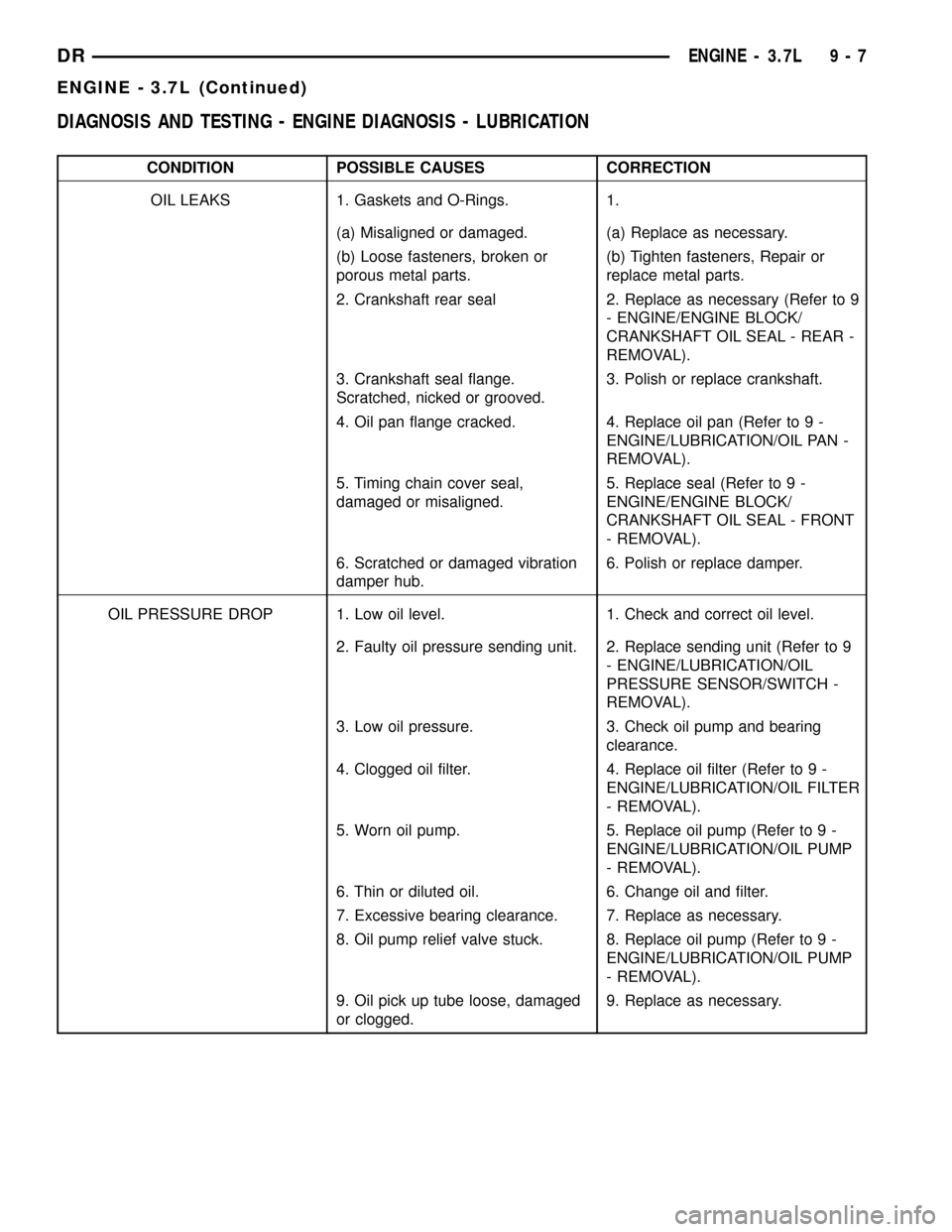
DIAGNOSIS AND TESTING - ENGINE DIAGNOSIS - LUBRICATION
CONDITION POSSIBLE CAUSES CORRECTION
OIL LEAKS 1. Gaskets and O-Rings. 1.
(a) Misaligned or damaged. (a) Replace as necessary.
(b) Loose fasteners, broken or
porous metal parts.(b) Tighten fasteners, Repair or
replace metal parts.
2. Crankshaft rear seal 2. Replace as necessary (Refer to 9
- ENGINE/ENGINE BLOCK/
CRANKSHAFT OIL SEAL - REAR -
REMOVAL).
3. Crankshaft seal flange.
Scratched, nicked or grooved.3. Polish or replace crankshaft.
4. Oil pan flange cracked. 4. Replace oil pan (Refer to 9 -
ENGINE/LUBRICATION/OIL PAN -
REMOVAL).
5. Timing chain cover seal,
damaged or misaligned.5. Replace seal (Refer to 9 -
ENGINE/ENGINE BLOCK/
CRANKSHAFT OIL SEAL - FRONT
- REMOVAL).
6. Scratched or damaged vibration
damper hub.6. Polish or replace damper.
OIL PRESSURE DROP 1. Low oil level. 1. Check and correct oil level.
2. Faulty oil pressure sending unit. 2. Replace sending unit (Refer to 9
- ENGINE/LUBRICATION/OIL
PRESSURE SENSOR/SWITCH -
REMOVAL).
3. Low oil pressure. 3. Check oil pump and bearing
clearance.
4. Clogged oil filter. 4. Replace oil filter (Refer to 9 -
ENGINE/LUBRICATION/OIL FILTER
- REMOVAL).
5. Worn oil pump. 5. Replace oil pump (Refer to 9 -
ENGINE/LUBRICATION/OIL PUMP
- REMOVAL).
6. Thin or diluted oil. 6. Change oil and filter.
7. Excessive bearing clearance. 7. Replace as necessary.
8. Oil pump relief valve stuck. 8. Replace oil pump (Refer to 9 -
ENGINE/LUBRICATION/OIL PUMP
- REMOVAL).
9. Oil pick up tube loose, damaged
or clogged.9. Replace as necessary.
DRENGINE - 3.7L 9 - 7
ENGINE - 3.7L (Continued)
Page 1237 of 2627
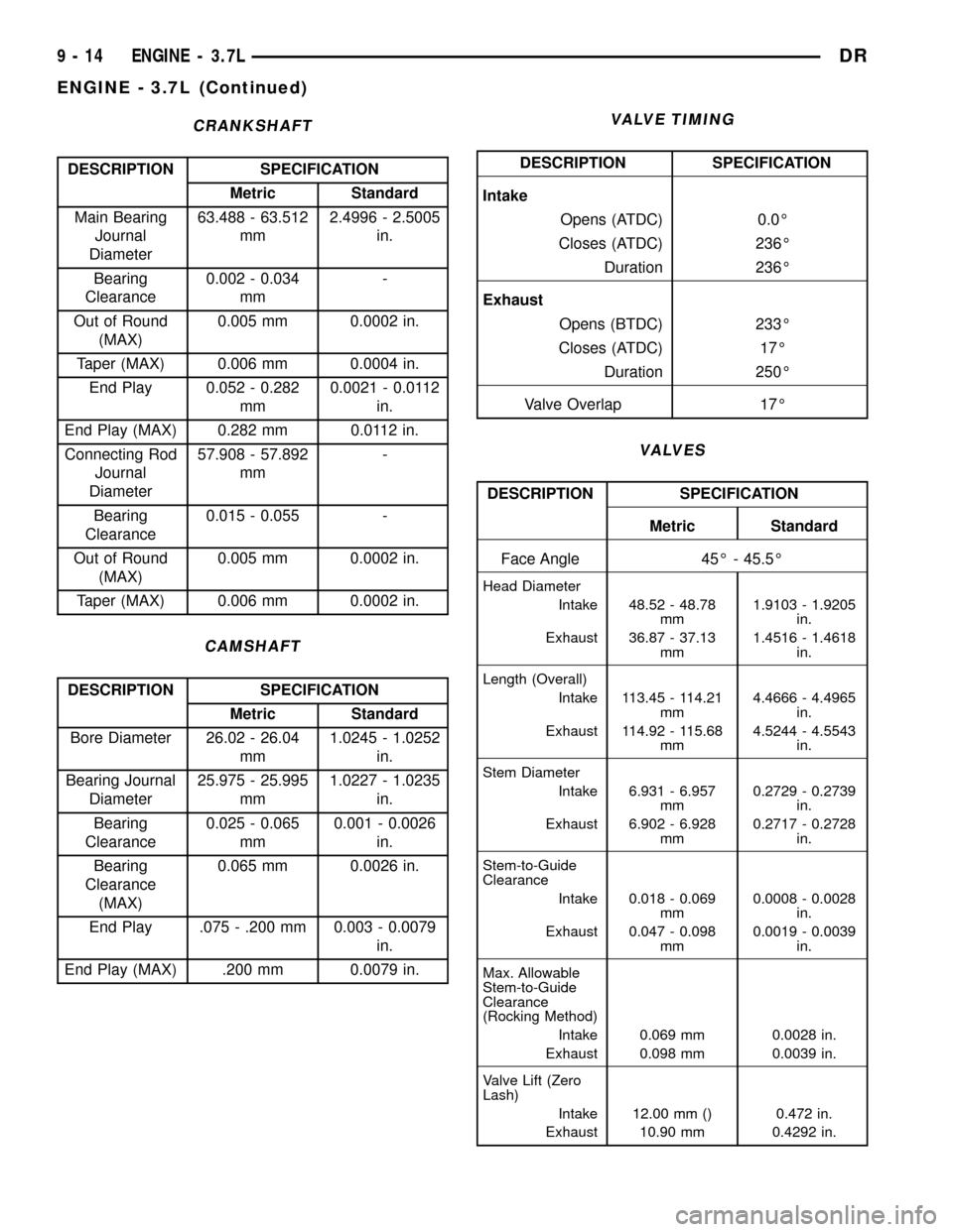
CRANKSHAFT
DESCRIPTION SPECIFICATION
Metric Standard
Main Bearing
Journal
Diameter63.488 - 63.512
mm2.4996 - 2.5005
in.
Bearing
Clearance0.002 - 0.034
mm-
Out of Round
(MAX)0.005 mm 0.0002 in.
Taper (MAX) 0.006 mm 0.0004 in.
End Play 0.052 - 0.282
mm0.0021 - 0.0112
in.
End Play (MAX) 0.282 mm 0.0112 in.
Connecting Rod
Journal
Diameter57.908 - 57.892
mm-
Bearing
Clearance0.015 - 0.055 -
Out of Round
(MAX)0.005 mm 0.0002 in.
Taper (MAX) 0.006 mm 0.0002 in.
CAMSHAFT
DESCRIPTION SPECIFICATION
Metric Standard
Bore Diameter 26.02 - 26.04
mm1.0245 - 1.0252
in.
Bearing Journal
Diameter25.975 - 25.995
mm1.0227 - 1.0235
in.
Bearing
Clearance0.025 - 0.065
mm0.001 - 0.0026
in.
Bearing
Clearance
(MAX)0.065 mm 0.0026 in.
End Play .075 - .200 mm 0.003 - 0.0079
in.
End Play (MAX) .200 mm 0.0079 in.
VALVE TIMING
DESCRIPTION SPECIFICATION
Intake
Opens (ATDC) 0.0É
Closes (ATDC) 236É
Duration 236É
Exhaust
Opens (BTDC) 233É
Closes (ATDC) 17É
Duration 250É
Valve Overlap 17É
VALVES
DESCRIPTION SPECIFICATION
Metric Standard
Face Angle 45É - 45.5É
Head Diameter
Intake 48.52 - 48.78
mm1.9103 - 1.9205
in.
Exhaust 36.87 - 37.13
mm1.4516 - 1.4618
in.
Length (Overall)
Intake 113.45 - 114.21
mm4.4666 - 4.4965
in.
Exhaust 114.92 - 115.68
mm4.5244 - 4.5543
in.
Stem Diameter
Intake 6.931 - 6.957
mm0.2729 - 0.2739
in.
Exhaust 6.902 - 6.928
mm0.2717 - 0.2728
in.
Stem-to-Guide
Clearance
Intake 0.018 - 0.069
mm0.0008 - 0.0028
in.
Exhaust 0.047 - 0.098
mm0.0019 - 0.0039
in.
Max. Allowable
Stem-to-Guide
Clearance
(Rocking Method)
Intake 0.069 mm 0.0028 in.
Exhaust 0.098 mm 0.0039 in.
Valve Lift (Zero
Lash)
Intake 12.00 mm () 0.472 in.
Exhaust 10.90 mm 0.4292 in.
9 - 14 ENGINE - 3.7LDR
ENGINE - 3.7L (Continued)
Page 1239 of 2627
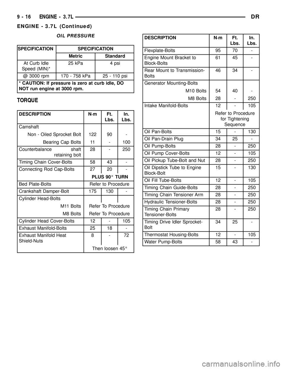
OIL PRESSURE
SPECIFICATION SPECIFICATION
Metric Standard
At Curb Idle
Speed (MIN)*25 kPa 4 psi
@ 3000 rpm 170 - 758 kPa 25 - 110 psi
* CAUTION: If pressure is zero at curb idle, DO
NOT run engine at 3000 rpm.
TORQUE
DESCRIPTION N´m Ft.
Lbs.In.
Lbs.
Camshaft
Non - Oiled Sprocket Bolt 122 90 -
Bearing Cap Bolts 11 - 100
Counterbalance shaft
retaining bolt28 - 250
Timing Chain Cover-Bolts 58 43 -
Connecting Rod Cap-Bolts 27 20 -
PLUS 90É TURN
Bed Plate-Bolts Refer to Procedure
Crankshaft Damper-Bolt 175 130 -
Cylinder Head-Bolts
M11 Bolts Refer To Procedure
M8 Bolts Refer To Procedure
Cylinder Head Cover-Bolts 12 - 105
Exhaust Manifold-Bolts 25 18 -
Exhaust Manifold Heat
Shield-Nuts8-72
Then loosen 45É
DESCRIPTION N´m Ft.
Lbs.In.
Lbs.
Flexplate-Bolts 95 70 -
Engine Mount Bracket to
Block-Bolts61 45 -
Rear Mount to Transmission-
Bolts46 34 -
Generator Mounting-Bolts
M10 Bolts 54 40 -
M8 Bolts 28 - 250
Intake Manifold-Bolts 12 - 105
Refer to Procedure
for Tightening
Sequence
Oil Pan-Bolts 15 - 130
Oil Pan-Drain Plug 34 25 -
Oil Pump-Bolts 28 - 250
Oil Pump Cover-Bolts 12 - 105
Oil Pickup Tube-Bolt and Nut 28 - 250
Oil Dipstick Tube to Engine
Block-Bolt15 - 130
Oil Fill Tube-Bolts 12 - 105
Timing Chain Guide-Bolts 28 - 250
Timing Chain Tensioner Arm 28 - 250
Hydraulic Tensioner-Bolts 28 - 250
Timing Chain Primary
Tensioner-Bolts28 - 250
Timing Drive Idler Sprocket-
Bolt34 25 -
Thermostat Housing-Bolts 12 - 105
Water Pump-Bolts 58 43 -
9 - 16 ENGINE - 3.7LDR
ENGINE - 3.7L (Continued)
Page 1245 of 2627

²Excessive steam (white smoke) emitting from
exhaust
²Coolant foaming
CYLINDER-TO-CYLINDER LEAKAGE TEST
To determine if an engine cylinder head gasket is
leaking between adjacent cylinders, follow the proce-
dures in Cylinder Compression Pressure Test (Refer
to 9 - ENGINE - DIAGNOSIS AND TESTING). An
engine cylinder head gasket leaking between adja-
cent cylinders will result in approximately a 50 - 70%
reduction in compression pressure.
CYLINDER-TO-WATER JACKET LEAKAGE TEST
WARNING: USE EXTREME CAUTION WHEN THE
ENGINE IS OPERATING WITH COOLANT PRES-
SURE CAP REMOVED.
VISUAL TEST METHOD
With the engine cool, remove the coolant pressure
cap. Start the engine and allow it to warm up until
thermostat opens.
If a large combustion/compression pressure leak
exists, bubbles will be visible in the coolant.
COOLING SYSTEM TESTER METHOD
WARNING: WITH COOLING SYSTEM TESTER IN
PLACE, PRESSURE WILL BUILD UP FAST. EXCES-
SIVE PRESSURE BUILT UP, BY CONTINUOUS
ENGINE OPERATION, MUST BE RELEASED TO A
SAFE PRESSURE POINT. NEVER PERMIT PRES-
SURE TO EXCEED 138 kPa (20 psi).
Install Cooling System Tester 7700 or equivalent to
pressure cap neck. Start the engine and observe the
tester's pressure gauge. If gauge pulsates with every
power stroke of a cylinder a combustion pressure
leak is evident.
CHEMICAL TEST METHOD
Combustion leaks into the cooling system can also
be checked by using Bloc-Chek Kit C-3685-A or
equivalent. Perform test following the procedures
supplied with the tool kit.
REMOVAL
(1) Disconnect the negative cable from the battery.
(2) Raise the vehicle on a hoist.
(3) Disconnect the exhaust pipe at the left side
exhaust manifold.
(4) Drain the engine coolant(Refer to 7 - COOL-
ING - STANDARD PROCEDURE).
(5) Lower the vehicle.(6) Remove the intake manifold(Refer to 9 -
ENGINE/MANIFOLDS/INTAKE MANIFOLD -
REMOVAL).
(7) Remove the master cylinder and booster assem-
bly(Refer to 5 - BRAKES/HYDRAULIC/MECHANI-
CAL/POWER BRAKE BOOSTER - REMOVAL).
(8) Remove the cylinder head cover(Refer to 9 -
ENGINE/CYLINDER HEAD/CYLINDER HEAD
COVER(S) - REMOVAL).
(9) Remove the fan shroud and fan blade assem-
bly(Refer to 7 - COOLING/ENGINE/RADIATOR FAN
- REMOVAL).
(10) Remove accessory drive belt(Refer to 7 -
COOLING/ACCESSORY DRIVE/DRIVE BELTS -
REMOVAL).
(11) Remove the power steering pump and set
aside.
(12) Rotate the crankshaft until the damper tim-
ing mark is aligned with TDC indicator mark (Fig.
5).
(13) Verify the V6 mark on the camshaft sprocket
is at the 12 o'clock position (Fig. 6). Rotate the crank-
shaft one turn if necessary.
(14) Remove the crankshaft damper(Refer to 9 -
ENGINE/ENGINE BLOCK/VIBRATION DAMPER -
REMOVAL).
(15) Remove the timing chain cover(Refer to 9 -
ENGINE/VALVE TIMING/TIMING BELT / CHAIN
COVER(S) - REMOVAL).
Fig. 5 Engine Top Dead Center
1 - TIMING CHAIN COVER
2 - CRANKSHAFT TIMING MARKS
9 - 22 ENGINE - 3.7LDR
CYLINDER HEAD - LEFT (Continued)