Battery DODGE RAM 1500 1998 2.G Workshop Manual
[x] Cancel search | Manufacturer: DODGE, Model Year: 1998, Model line: RAM 1500, Model: DODGE RAM 1500 1998 2.GPages: 2627
Page 1577 of 2627
QUICK CONNECT FITTING
DESCRIPTION
Different types of quick-connect fittings are used to
attach various fuel system components, lines and
tubes. These are: a single-tab type, a two-tab type or
a plastic retainer ring type. Some are equipped with
safety latch clips. Some may require the use of a spe-
cial tool for disconnection and removal. Refer to
Quick-Connect Fittings Removal/Installation for more
information.
CAUTION: The interior components (o-rings, clips)
of quick-connect fittings are not serviced sepa-
rately, but new plastic spacers are available for
some types. If service parts are not available, do
not attempt to repair the damaged fitting or fuel line
(tube). If repair is necessary, replace the complete
fuel line (tube) assembly.
STANDARD PROCEDURE - QUICK-CONNECT
FITTINGS
Also refer to Fuel Tubes/Lines/Hoses and Clamps.
Different types of quick-connect fittings are used to
attach various fuel system components, lines and
tubes. These are: a single-tab type, a two-tab type or
a plastic retainer ring type. Safety latch clips are
used on certain components/lines. Certain fittings
may require use of a special tool for disconnection.
DISCONNECTING
WARNING: THE FUEL SYSTEM IS UNDER A CON-
STANT PRESSURE (EVEN WITH ENGINE OFF).
BEFORE SERVICING ANY FUEL SYSTEM HOSE,
FITTING OR LINE, FUEL SYSTEM PRESSURE MUST
BE RELEASED. REFER TO FUEL SYSTEM PRES-
SURE RELEASE PROCEDURE.
CAUTION: The interior components (o-rings, spac-
ers) of some types of quick-connect fitting are not
serviced separately. If service parts are not avail-
able, do not attempt to repair a damaged fitting or
fuel line. If repair is necessary, replace complete
fuel line assembly.
(1) Perform fuel pressure release procedure. Refer
to Fuel Pressure Release Procedure.
(2) Disconnect negative battery cable from battery.
(3) Clean fitting of any foreign material before dis-
assembly.
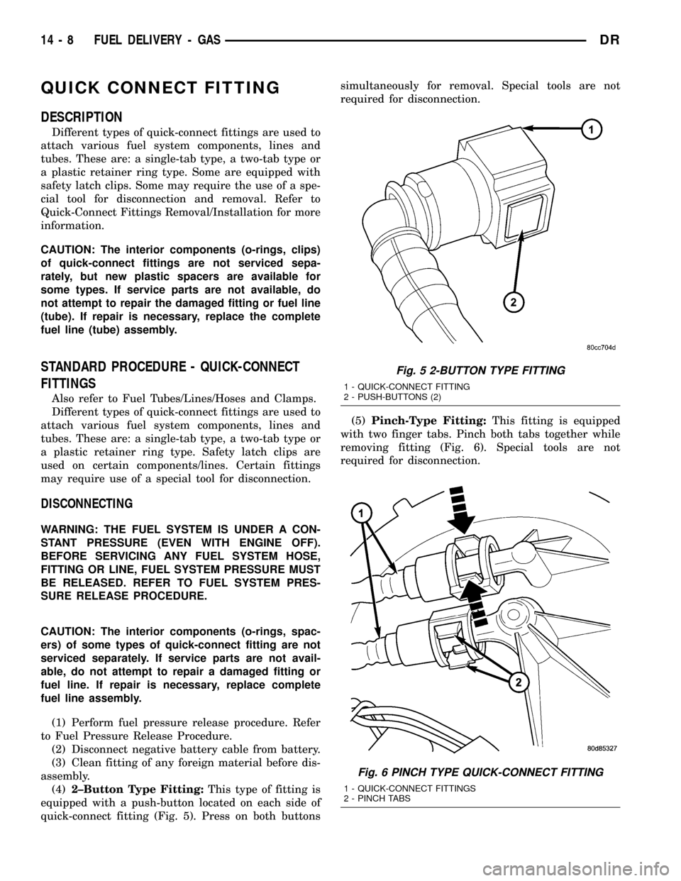
(4)2±Button Type Fitting:This type of fitting is
equipped with a push-button located on each side of
quick-connect fitting (Fig. 5). Press on both buttonssimultaneously for removal. Special tools are not
required for disconnection.
(5)Pinch-Type Fitting:This fitting is equipped
with two finger tabs. Pinch both tabs together while
removing fitting (Fig. 6). Special tools are not
required for disconnection.
Fig. 5 2-BUTTON TYPE FITTING
1 - QUICK-CONNECT FITTING
2 - PUSH-BUTTONS (2)
Fig. 6 PINCH TYPE QUICK-CONNECT FITTING
1 - QUICK-CONNECT FITTINGS
2 - PINCH TABS
14 - 8 FUEL DELIVERY - GASDR
Page 1580 of 2627
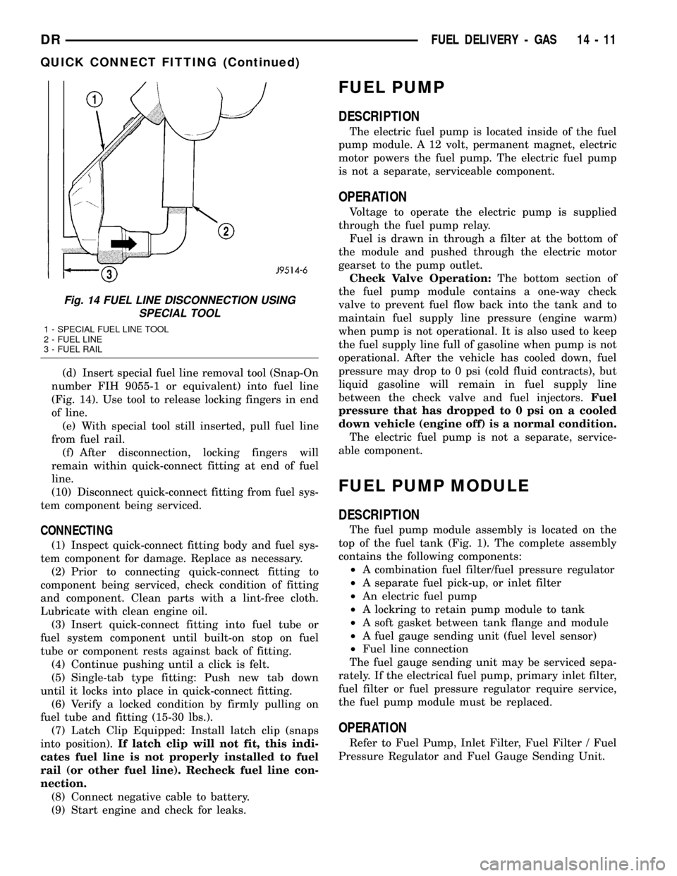
(d) Insert special fuel line removal tool (Snap-On
number FIH 9055-1 or equivalent) into fuel line
(Fig. 14). Use tool to release locking fingers in end
of line.
(e) With special tool still inserted, pull fuel line
from fuel rail.
(f) After disconnection, locking fingers will
remain within quick-connect fitting at end of fuel
line.
(10) Disconnect quick-connect fitting from fuel sys-
tem component being serviced.
CONNECTING
(1) Inspect quick-connect fitting body and fuel sys-
tem component for damage. Replace as necessary.
(2) Prior to connecting quick-connect fitting to
component being serviced, check condition of fitting
and component. Clean parts with a lint-free cloth.
Lubricate with clean engine oil.
(3) Insert quick-connect fitting into fuel tube or
fuel system component until built-on stop on fuel
tube or component rests against back of fitting.
(4) Continue pushing until a click is felt.
(5) Single-tab type fitting: Push new tab down
until it locks into place in quick-connect fitting.
(6) Verify a locked condition by firmly pulling on
fuel tube and fitting (15-30 lbs.).
(7) Latch Clip Equipped: Install latch clip (snaps
into position).If latch clip will not fit, this indi-
cates fuel line is not properly installed to fuel
rail (or other fuel line). Recheck fuel line con-
nection.
(8) Connect negative cable to battery.
(9) Start engine and check for leaks.
FUEL PUMP
DESCRIPTION
The electric fuel pump is located inside of the fuel
pump module. A 12 volt, permanent magnet, electric
motor powers the fuel pump. The electric fuel pump
is not a separate, serviceable component.
OPERATION
Voltage to operate the electric pump is supplied
through the fuel pump relay.
Fuel is drawn in through a filter at the bottom of
the module and pushed through the electric motor
gearset to the pump outlet.
Check Valve Operation:The bottom section of
the fuel pump module contains a one-way check
valve to prevent fuel flow back into the tank and to
maintain fuel supply line pressure (engine warm)
when pump is not operational. It is also used to keep
the fuel supply line full of gasoline when pump is not
operational. After the vehicle has cooled down, fuel
pressure may drop to 0 psi (cold fluid contracts), but
liquid gasoline will remain in fuel supply line
between the check valve and fuel injectors.Fuel
pressure that has dropped to 0 psi on a cooled
down vehicle (engine off) is a normal condition.
The electric fuel pump is not a separate, service-
able component.
FUEL PUMP MODULE
DESCRIPTION
The fuel pump module assembly is located on the
top of the fuel tank (Fig. 1). The complete assembly
contains the following components:
²A combination fuel filter/fuel pressure regulator
²A separate fuel pick-up, or inlet filter
²An electric fuel pump
²A lockring to retain pump module to tank
²A soft gasket between tank flange and module
²A fuel gauge sending unit (fuel level sensor)
²Fuel line connection
The fuel gauge sending unit may be serviced sepa-
rately. If the electrical fuel pump, primary inlet filter,
fuel filter or fuel pressure regulator require service,
the fuel pump module must be replaced.
OPERATION
Refer to Fuel Pump, Inlet Filter, Fuel Filter / Fuel
Pressure Regulator and Fuel Gauge Sending Unit.
Fig. 14 FUEL LINE DISCONNECTION USING
SPECIAL TOOL
1 - SPECIAL FUEL LINE TOOL
2 - FUEL LINE
3 - FUEL RAIL
DRFUEL DELIVERY - GAS 14 - 11
QUICK CONNECT FITTING (Continued)
Page 1582 of 2627
REMOVAL
3.7L V-6
WARNING: THE FUEL SYSTEM IS UNDER CON-
STANT PRESSURE EVEN WITH ENGINE OFF.
BEFORE SERVICING FUEL RAIL, FUEL SYSTEM
PRESSURE MUST BE RELEASED.
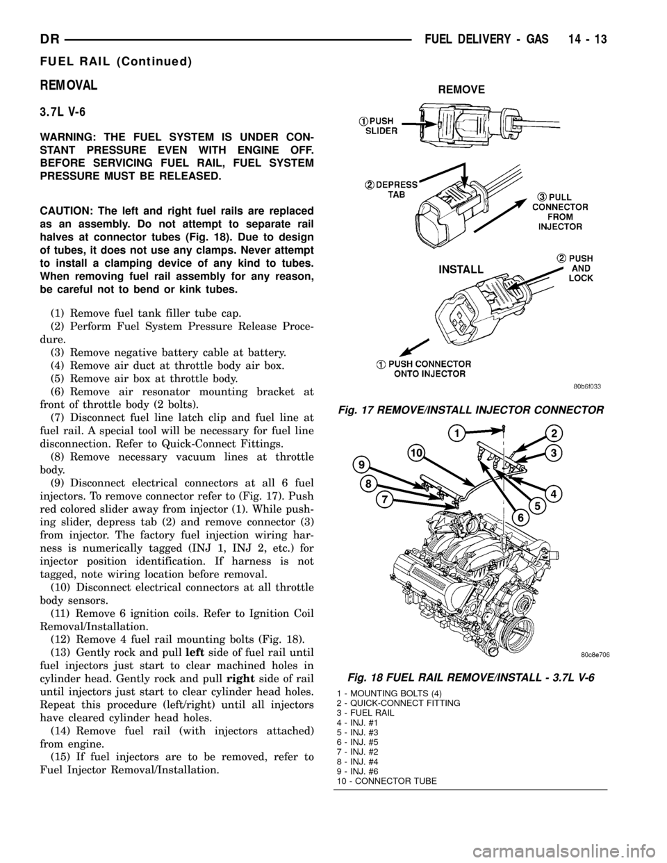
CAUTION: The left and right fuel rails are replaced
as an assembly. Do not attempt to separate rail
halves at connector tubes (Fig. 18). Due to design
of tubes, it does not use any clamps. Never attempt
to install a clamping device of any kind to tubes.
When removing fuel rail assembly for any reason,
be careful not to bend or kink tubes.
(1) Remove fuel tank filler tube cap.
(2) Perform Fuel System Pressure Release Proce-
dure.
(3) Remove negative battery cable at battery.
(4) Remove air duct at throttle body air box.
(5) Remove air box at throttle body.
(6) Remove air resonator mounting bracket at
front of throttle body (2 bolts).
(7) Disconnect fuel line latch clip and fuel line at
fuel rail. A special tool will be necessary for fuel line
disconnection. Refer to Quick-Connect Fittings.
(8) Remove necessary vacuum lines at throttle
body.
(9) Disconnect electrical connectors at all 6 fuel
injectors. To remove connector refer to (Fig. 17). Push
red colored slider away from injector (1). While push-
ing slider, depress tab (2) and remove connector (3)
from injector. The factory fuel injection wiring har-
ness is numerically tagged (INJ 1, INJ 2, etc.) for
injector position identification. If harness is not
tagged, note wiring location before removal.
(10) Disconnect electrical connectors at all throttle
body sensors.
(11) Remove 6 ignition coils. Refer to Ignition Coil
Removal/Installation.
(12) Remove 4 fuel rail mounting bolts (Fig. 18).
(13) Gently rock and pullleftside of fuel rail until
fuel injectors just start to clear machined holes in
cylinder head. Gently rock and pullrightside of rail
until injectors just start to clear cylinder head holes.
Repeat this procedure (left/right) until all injectors
have cleared cylinder head holes.
(14) Remove fuel rail (with injectors attached)
from engine.
(15) If fuel injectors are to be removed, refer to
Fuel Injector Removal/Installation.
Fig. 17 REMOVE/INSTALL INJECTOR CONNECTOR
Fig. 18 FUEL RAIL REMOVE/INSTALL - 3.7L V-6
1 - MOUNTING BOLTS (4)
2 - QUICK-CONNECT FITTING
3 - FUEL RAIL
4 - INJ. #1
5 - INJ. #3
6 - INJ. #5
7 - INJ. #2
8 - INJ. #4
9 - INJ. #6
10 - CONNECTOR TUBE
DRFUEL DELIVERY - GAS 14 - 13
FUEL RAIL (Continued)
Page 1583 of 2627
4.7L V-8
WARNING: THE FUEL SYSTEM IS UNDER CON-
STANT PRESSURE EVEN WITH ENGINE OFF.
BEFORE SERVICING FUEL RAIL, FUEL SYSTEM
PRESSURE MUST BE RELEASED.
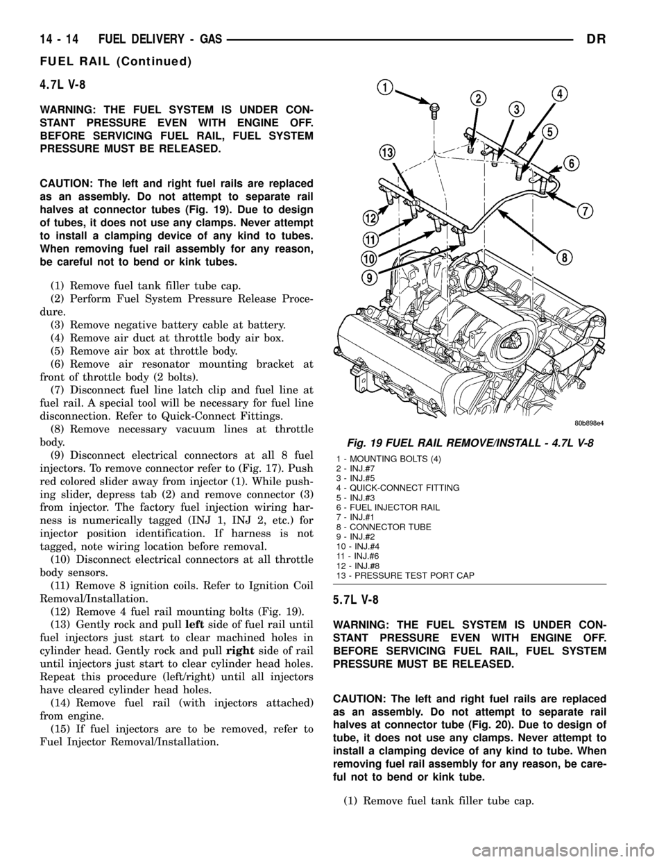
CAUTION: The left and right fuel rails are replaced
as an assembly. Do not attempt to separate rail
halves at connector tubes (Fig. 19). Due to design
of tubes, it does not use any clamps. Never attempt
to install a clamping device of any kind to tubes.
When removing fuel rail assembly for any reason,
be careful not to bend or kink tubes.
(1) Remove fuel tank filler tube cap.
(2) Perform Fuel System Pressure Release Proce-
dure.
(3) Remove negative battery cable at battery.
(4) Remove air duct at throttle body air box.
(5) Remove air box at throttle body.
(6) Remove air resonator mounting bracket at
front of throttle body (2 bolts).
(7) Disconnect fuel line latch clip and fuel line at
fuel rail. A special tool will be necessary for fuel line
disconnection. Refer to Quick-Connect Fittings.
(8) Remove necessary vacuum lines at throttle
body.
(9) Disconnect electrical connectors at all 8 fuel
injectors. To remove connector refer to (Fig. 17). Push
red colored slider away from injector (1). While push-
ing slider, depress tab (2) and remove connector (3)
from injector. The factory fuel injection wiring har-
ness is numerically tagged (INJ 1, INJ 2, etc.) for
injector position identification. If harness is not
tagged, note wiring location before removal.
(10) Disconnect electrical connectors at all throttle
body sensors.
(11) Remove 8 ignition coils. Refer to Ignition Coil
Removal/Installation.
(12) Remove 4 fuel rail mounting bolts (Fig. 19).
(13) Gently rock and pullleftside of fuel rail until
fuel injectors just start to clear machined holes in
cylinder head. Gently rock and pullrightside of rail
until injectors just start to clear cylinder head holes.
Repeat this procedure (left/right) until all injectors
have cleared cylinder head holes.
(14) Remove fuel rail (with injectors attached)
from engine.
(15) If fuel injectors are to be removed, refer to
Fuel Injector Removal/Installation.
5.7L V-8
WARNING: THE FUEL SYSTEM IS UNDER CON-
STANT PRESSURE EVEN WITH ENGINE OFF.
BEFORE SERVICING FUEL RAIL, FUEL SYSTEM
PRESSURE MUST BE RELEASED.
CAUTION: The left and right fuel rails are replaced
as an assembly. Do not attempt to separate rail
halves at connector tube (Fig. 20). Due to design of
tube, it does not use any clamps. Never attempt to
install a clamping device of any kind to tube. When
removing fuel rail assembly for any reason, be care-
ful not to bend or kink tube.
(1) Remove fuel tank filler tube cap.
Fig. 19 FUEL RAIL REMOVE/INSTALL - 4.7L V-8
1 - MOUNTING BOLTS (4)
2 - INJ.#7
3 - INJ.#5
4 - QUICK-CONNECT FITTING
5 - INJ.#3
6 - FUEL INJECTOR RAIL
7 - INJ.#1
8 - CONNECTOR TUBE
9 - INJ.#2
10 - INJ.#4
11 - INJ.#6
12 - INJ.#8
13 - PRESSURE TEST PORT CAP
14 - 14 FUEL DELIVERY - GASDR
FUEL RAIL (Continued)
Page 1584 of 2627
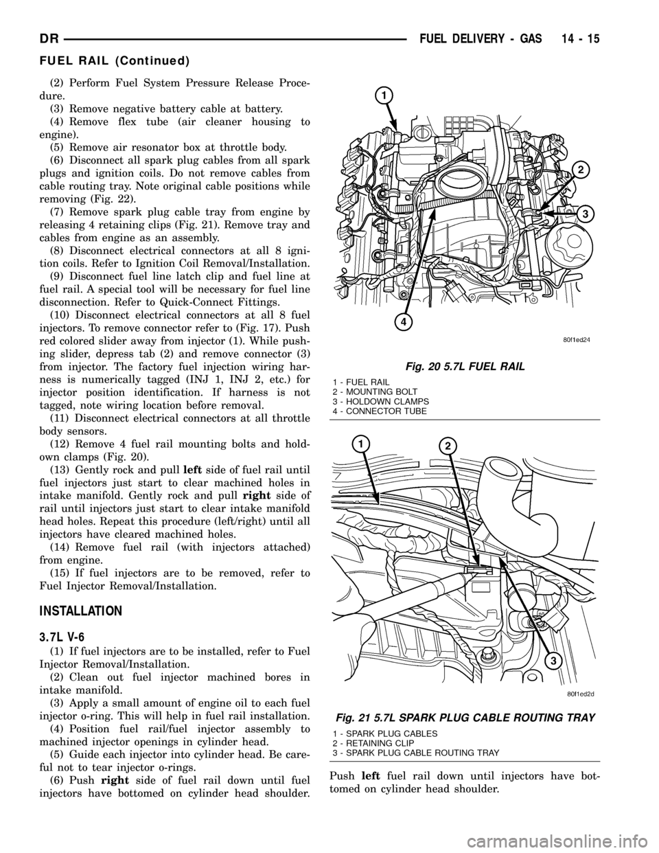
(2) Perform Fuel System Pressure Release Proce-
dure.
(3) Remove negative battery cable at battery.
(4) Remove flex tube (air cleaner housing to
engine).
(5) Remove air resonator box at throttle body.
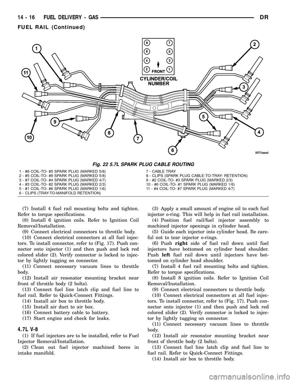
(6) Disconnect all spark plug cables from all spark
plugs and ignition coils. Do not remove cables from
cable routing tray. Note original cable positions while
removing (Fig. 22).
(7) Remove spark plug cable tray from engine by
releasing 4 retaining clips (Fig. 21). Remove tray and
cables from engine as an assembly.
(8) Disconnect electrical connectors at all 8 igni-
tion coils. Refer to Ignition Coil Removal/Installation.
(9) Disconnect fuel line latch clip and fuel line at
fuel rail. A special tool will be necessary for fuel line
disconnection. Refer to Quick-Connect Fittings.
(10) Disconnect electrical connectors at all 8 fuel
injectors. To remove connector refer to (Fig. 17). Push
red colored slider away from injector (1). While push-
ing slider, depress tab (2) and remove connector (3)
from injector. The factory fuel injection wiring har-
ness is numerically tagged (INJ 1, INJ 2, etc.) for
injector position identification. If harness is not
tagged, note wiring location before removal.
(11) Disconnect electrical connectors at all throttle
body sensors.
(12) Remove 4 fuel rail mounting bolts and hold-
own clamps (Fig. 20).
(13) Gently rock and pullleftside of fuel rail until
fuel injectors just start to clear machined holes in
intake manifold. Gently rock and pullrightside of
rail until injectors just start to clear intake manifold
head holes. Repeat this procedure (left/right) until all
injectors have cleared machined holes.
(14) Remove fuel rail (with injectors attached)
from engine.
(15) If fuel injectors are to be removed, refer to
Fuel Injector Removal/Installation.
INSTALLATION
3.7L V-6
(1) If fuel injectors are to be installed, refer to Fuel
Injector Removal/Installation.
(2) Clean out fuel injector machined bores in
intake manifold.
(3) Apply a small amount of engine oil to each fuel
injector o-ring. This will help in fuel rail installation.
(4) Position fuel rail/fuel injector assembly to
machined injector openings in cylinder head.
(5) Guide each injector into cylinder head. Be care-
ful not to tear injector o-rings.
(6) Pushrightside of fuel rail down until fuel
injectors have bottomed on cylinder head shoulder.Pushleftfuel rail down until injectors have bot-
tomed on cylinder head shoulder.
Fig. 20 5.7L FUEL RAIL
1 - FUEL RAIL
2 - MOUNTING BOLT
3 - HOLDOWN CLAMPS
4 - CONNECTOR TUBE
Fig. 21 5.7L SPARK PLUG CABLE ROUTING TRAY
1 - SPARK PLUG CABLES
2 - RETAINING CLIP
3 - SPARK PLUG CABLE ROUTING TRAY
DRFUEL DELIVERY - GAS 14 - 15
FUEL RAIL (Continued)
Page 1585 of 2627
(7) Install 4 fuel rail mounting bolts and tighten.
Refer to torque specifications.
(8) Install 6 ignition coils. Refer to Ignition Coil
Removal/Installation.
(9) Connect electrical connectors to throttle body.
(10) Connect electrical connectors at all fuel injec-
tors. To install connector, refer to (Fig. 17). Push con-
nector onto injector (1) and then push and lock red
colored slider (2). Verify connector is locked to injec-
tor by lightly tugging on connector.
(11) Connect necessary vacuum lines to throttle
body.
(12) Install air resonator mounting bracket near
front of throttle body (2 bolts).
(13) Connect fuel line latch clip and fuel line to
fuel rail. Refer to Quick-Connect Fittings.
(14) Install air box to throttle body.
(15) Install air duct to air box.
(16) Connect battery cable to battery.
(17) Start engine and check for leaks.
4.7L V-8
(1) If fuel injectors are to be installed, refer to Fuel
Injector Removal/Installation.
(2) Clean out fuel injector machined bores in
intake manifold.(3) Apply a small amount of engine oil to each fuel
injector o-ring. This will help in fuel rail installation.
(4) Position fuel rail/fuel injector assembly to
machined injector openings in cylinder head.
(5) Guide each injector into cylinder head. Be care-
ful not to tear injector o-rings.
(6) Pushrightside of fuel rail down until fuel
injectors have bottomed on cylinder head shoulder.
Pushleftfuel rail down until injectors have bot-
tomed on cylinder head shoulder.
(7) Install 4 fuel rail mounting bolts and tighten.
Refer to torque specifications.
(8) Install 8 ignition coils. Refer to Ignition Coil
Removal/Installation.
(9) Connect electrical connectors to throttle body.
(10) Connect electrical connectors at all fuel injec-
tors. To install connector, refer to (Fig. 17). Push con-
nector onto injector (1) and then push and lock red
colored slider (2). Verify connector is locked to injec-
tor by lightly tugging on connector.
(11) Connect necessary vacuum lines to throttle
body.
(12) Install air resonator mounting bracket near
front of throttle body (2 bolts).
(13) Connect fuel line latch clip and fuel line to
fuel rail. Refer to Quick-Connect Fittings.
(14) Install air box to throttle body.
Fig. 22 5.7L SPARK PLUG CABLE ROUTING
1 - #8 COIL-TO- #5 SPARK PLUG (MARKED 5/8) 7 - CABLE TRAY
2 - #5 COIL-TO- #8 SPARK PLUG (MARKED 5/8) 8 - CLIPS (SPARK PLUG CABLE-TO-TRAY- RETENTION)
3 - #7 COIL-TO- #4 SPARK PLUG (MARKED 4/7) 9 - #2 COIL-TO- #3 SPARK PLUG (MARKED 2/3)
4 - #3 COIL-TO- #2 SPARK PLUG (MARKED 2/3) 10 - #6 COIL-TO- #1 SPARK PLUG (MARKED 1/6)
5 - #1 COIL-TO- #6 SPARK PLUG (MARKED 1/6) 11 - #4 COIL-TO- #7 SPARK PLUG (MARKED 4/7)
6 - CLIPS (TRAY-TO-MANIFOLD RETENTION)
14 - 16 FUEL DELIVERY - GASDR
FUEL RAIL (Continued)
Page 1586 of 2627
(15) Install air duct to air box.
(16) Connect battery cable to battery.
(17) Start engine and check for leaks.
5.7L V-8
(1) If fuel injectors are to be installed, refer to Fuel
Injector Removal/Installation.
(2) Clean out fuel injector machined bores in
intake manifold.
(3) Apply a small amount of engine oil to each fuel
injector o-ring. This will help in fuel rail installation.
(4) Position fuel rail/fuel injector assembly to
machined injector openings in intake manifold.
(5) Guide each injector into intake manifold. Be
careful not to tear injector o-rings.
(6) Pushrightside of fuel rail down until fuel
injectors have bottomed on shoulders. Pushleftfuel
rail down until injectors have bottomed on shoulders.
(7) Install 4 fuel rail holdown clamps and 4 mount-
ing bolts. Refer to Torque Specifications.
(8) Position spark plug cable tray and cable assem-
bly to intake manifold. Snap 4 cable tray retaining
clips into intake manifold.
(9) Install all cables to spark plugs and ignition
coils.
(10) Connect electrical connector to throttle body.
(11) Install electrical connectors to all 8 ignition
coils. Refer to Ignition Coil Removal/Installation.
(12) Connect electrical connector to throttle body.
(13) Connect electrical connectors at all fuel injec-
tors. To install connector, refer to (Fig. 17). Push con-
nector onto injector (1) and then push and lock red
colored slider (2). Verify connector is locked to injec-
tor by lightly tugging on connector.
(14) Connect fuel line latch clip and fuel line to
fuel rail. Refer to Quick-Connect Fittings.
(15) Install air resonator to throttle body (2 bolts).
(16) Install flexible air duct to air box.
(17) Connect battery cable to battery.
(18) Start engine and check for leaks.
FUEL TANK
DESCRIPTION
The fuel tank is constructed of a plastic material.
Its main functions are for fuel storage and for place-
ment of the fuel pump module, and (if equipped) cer-
tain ORVR components.
OPERATION
All models pass a full 360 degree rollover test
without fuel leakage. To accomplish this, fuel and
vapor flow controls are required for all fuel tank con-
nections.Two check (control) valves are mounted into the
top of the fuel tank. Refer to Fuel Tank Check Valve
for additional information.
An evaporation control system is connected to the
fuel tank to reduce emissions of fuel vapors into the
atmosphere. When fuel evaporates from the fuel
tank, vapors pass through vent hoses or tubes to a
charcoal canister where they are temporarily held.
When the engine is running, the vapors are drawn
into the intake manifold. Certain models are also
equipped with a self-diagnosing system using a Leak
Detection Pump (LDP) and/or an On-Board Refueling
Vapor Recovery (ORVR) system. Refer to Emission
Control System for additional information.
REMOVAL- EXCEPT DIESEL
Fuel Tank Draining
WARNING: THE FUEL SYSTEM MAY BE UNDER
CONSTANT FUEL PRESSURE EVEN WITH THE
ENGINE OFF. THIS PRESSURE MUST BE
RELEASED BEFORE SERVICING FUEL TANK.
Two different procedures may be used to drain fuel
tank: through the fuel fill fitting on tank, or using
the DRBtscan tool. Due to a one-way check valve
installed into the fuel fill opening fitting at the tank,
the tank cannot be drained conventionally at the fill
cap.
The quickest draining procedure involves removing
the rubber fuel fill hose.
As an alternative procedure, the electric fuel pump
may be activated allowing tank to be drained at fuel
rail connection. Refer to DRB scan tool for fuel pump
activation procedures. Before disconnecting fuel line
at fuel rail, release fuel pressure. Refer to the Fuel
System Pressure Release Procedure for procedures.
Attach end of special test hose tool number 6541,
6539, 6631 or 6923 at fuel rail disconnection (tool
number will depend on model and/or engine applica-
tion). Position opposite end of this hose tool to an
approved gasoline draining station. Activate fuel
pump and drain tank until empty.
If electric fuel pump is not operating, fuel must be
drained through fuel fill fitting at tank. Refer to fol-
lowing procedures.
(1) Release fuel system pressure.
(2) Raise vehicle.
(3) Thoroughly clean area around fuel fill fitting
and rubber fuel fill hose at tank.
(4) If vehicle is equipped with 4 doors and a 6 foot
(short) box, remove left-rear tire/wheel.
(5) Loosen clamp (Fig. 23) and disconnect rubber
fuel fill hose at tank fitting. Using an approved gas
holding tank, drain fuel tank through this fitting.
DRFUEL DELIVERY - GAS 14 - 17
FUEL RAIL (Continued)
Page 1591 of 2627
ACCELERATOR PEDAL
POSITION SENSOR
DESCRIPTION
The Accelerator Pedal Position Sensor (APPS)
assembly is located under the vehicle battery tray. A
cable connects the assembly to the accelerator pedal.
A plastic cover with a movable door is used to cover
the assembly.
The APPS is used only with the 5.7L V-8 engine.
OPERATION
The Accelerator Pedal Position Sensor (APPS) is a
linear potentiometer. It provides the Powertrain Con-
trol Module (PCM) with a DC voltage signal propor-
tional to the angle, or position of the accelerator
pedal. The APPS signal is translated (along with
other sensors) to place the throttle plate (within the
throttle body) to a pre-determined position.
A mechanical cable is used between the accelerator
pedal and the APPS assembly. Although a cable is
used between the pedal and APPS, a mechanical
cable is not used at the throttle body. Throttle plate
position is electrically determined.
REMOVAL
The APPS is serviced (replaced) as one assembly
including the sensor, plastic housing and cable. The
APPS assembly is located under the vehicle battery
tray (Fig. 2). Access to APPS is gained from over top
of left / front tire.
(1) Disconnect negative battery cable at battery.
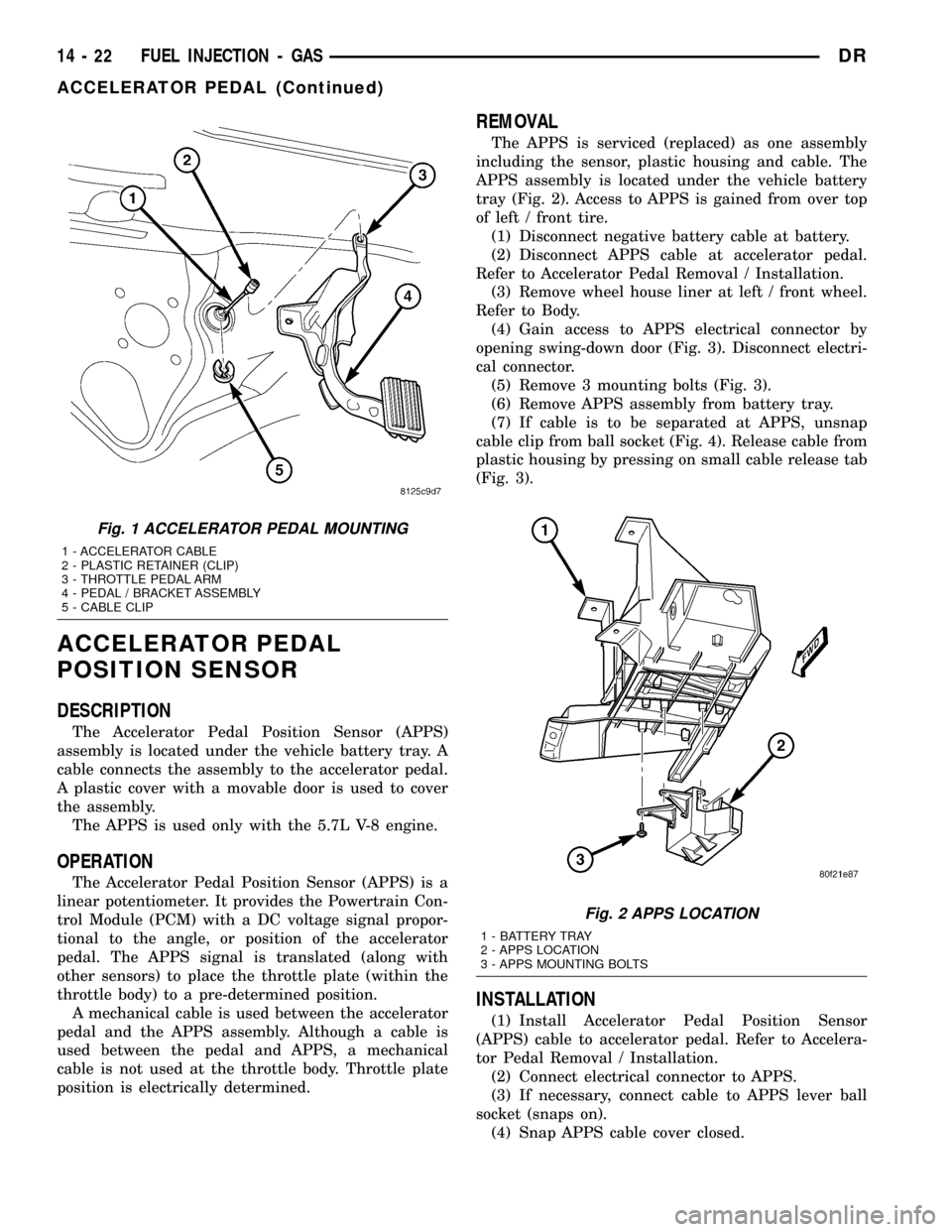
(2) Disconnect APPS cable at accelerator pedal.
Refer to Accelerator Pedal Removal / Installation.
(3) Remove wheel house liner at left / front wheel.
Refer to Body.
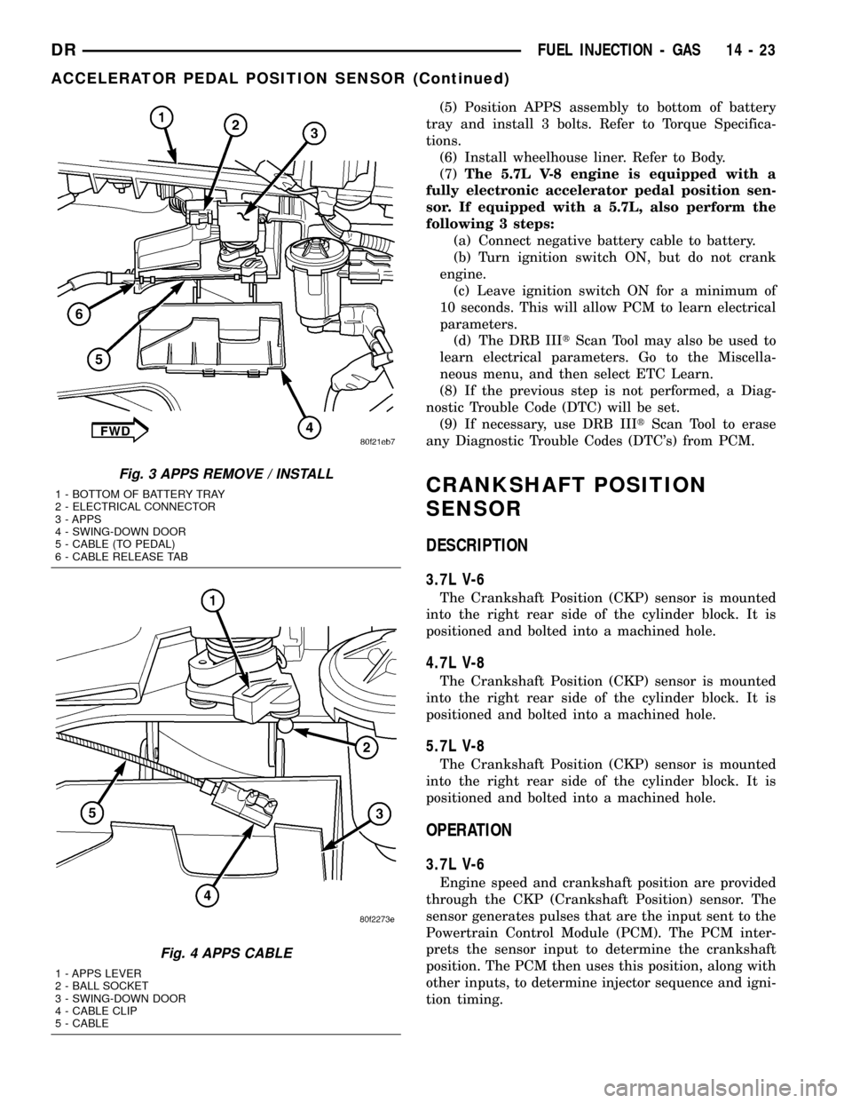
(4) Gain access to APPS electrical connector by
opening swing-down door (Fig. 3). Disconnect electri-
cal connector.
(5) Remove 3 mounting bolts (Fig. 3).
(6) Remove APPS assembly from battery tray.
(7) If cable is to be separated at APPS, unsnap
cable clip from ball socket (Fig. 4). Release cable from
plastic housing by pressing on small cable release tab
(Fig. 3).
INSTALLATION
(1) Install Accelerator Pedal Position Sensor
(APPS) cable to accelerator pedal. Refer to Accelera-
tor Pedal Removal / Installation.
(2) Connect electrical connector to APPS.
(3) If necessary, connect cable to APPS lever ball
socket (snaps on).
(4) Snap APPS cable cover closed.
Fig. 1 ACCELERATOR PEDAL MOUNTING
1 - ACCELERATOR CABLE
2 - PLASTIC RETAINER (CLIP)
3 - THROTTLE PEDAL ARM
4 - PEDAL / BRACKET ASSEMBLY
5 - CABLE CLIP
Fig. 2 APPS LOCATION
1 - BATTERY TRAY
2 - APPS LOCATION
3 - APPS MOUNTING BOLTS
14 - 22 FUEL INJECTION - GASDR
ACCELERATOR PEDAL (Continued)
Page 1592 of 2627
(5) Position APPS assembly to bottom of battery
tray and install 3 bolts. Refer to Torque Specifica-
tions.
(6) Install wheelhouse liner. Refer to Body.
(7)The 5.7L V-8 engine is equipped with a
fully electronic accelerator pedal position sen-
sor. If equipped with a 5.7L, also perform the
following 3 steps:
(a) Connect negative battery cable to battery.
(b) Turn ignition switch ON, but do not crank
engine.
(c) Leave ignition switch ON for a minimum of
10 seconds. This will allow PCM to learn electrical
parameters.
(d) The DRB IIItScan Tool may also be used to
learn electrical parameters. Go to the Miscella-
neous menu, and then select ETC Learn.
(8) If the previous step is not performed, a Diag-
nostic Trouble Code (DTC) will be set.
(9) If necessary, use DRB IIItScan Tool to erase
any Diagnostic Trouble Codes (DTC's) from PCM.
CRANKSHAFT POSITION
SENSOR
DESCRIPTION
3.7L V-6
The Crankshaft Position (CKP) sensor is mounted
into the right rear side of the cylinder block. It is
positioned and bolted into a machined hole.
4.7L V-8
The Crankshaft Position (CKP) sensor is mounted
into the right rear side of the cylinder block. It is
positioned and bolted into a machined hole.
5.7L V-8
The Crankshaft Position (CKP) sensor is mounted
into the right rear side of the cylinder block. It is
positioned and bolted into a machined hole.
OPERATION
3.7L V-6
Engine speed and crankshaft position are provided
through the CKP (Crankshaft Position) sensor. The
sensor generates pulses that are the input sent to the
Powertrain Control Module (PCM). The PCM inter-
prets the sensor input to determine the crankshaft
position. The PCM then uses this position, along with
other inputs, to determine injector sequence and igni-
tion timing.
Fig. 3 APPS REMOVE / INSTALL
1 - BOTTOM OF BATTERY TRAY
2 - ELECTRICAL CONNECTOR
3 - APPS
4 - SWING-DOWN DOOR
5 - CABLE (TO PEDAL)
6 - CABLE RELEASE TAB
Fig. 4 APPS CABLE
1 - APPS LEVER
2 - BALL SOCKET
3 - SWING-DOWN DOOR
4 - CABLE CLIP
5 - CABLE
DRFUEL INJECTION - GAS 14 - 23
ACCELERATOR PEDAL POSITION SENSOR (Continued)
Page 1596 of 2627
stream. The spraying action atomizes the fuel, add-
ing it to the air entering the combustion chamber.
The nozzle (outlet) ends of the injectors are posi-
tioned into openings in the intake manifold just
above the intake valve ports of the cylinder head.
The engine wiring harness connector for each fuel
injector is equipped with an attached numerical tag
(INJ 1, INJ 2 etc.). This is used to identify each fuel
injector.
The injectors are energized individually in a
sequential order by the Powertrain Control Module
(PCM). The PCM will adjust injector pulse width by
switching the ground path to each individual injector
on and off. Injector pulse width is the period of time
that the injector is energized. The PCM will adjust
injector pulse width based on various inputs it
receives.
Battery voltage is supplied to the injectors through
the ASD relay.
The PCM determines injector pulse width based on
various inputs.
OPERATION - PCM OUTPUT
The nozzle ends of the injectors are positioned into
openings in the intake manifold just above the intake
valve ports of the cylinder head. The engine wiring
harness connector for each fuel injector is equipped
with an attached numerical tag (INJ 1, INJ 2 etc.).
This is used to identify each fuel injector with its
respective cylinder number.
The injectors are energized individually in a
sequential order by the Powertrain Control Module
(PCM). The PCM will adjust injector pulse width by
switching the ground path to each individual injector
on and off. Injector pulse width is the period of time
that the injector is energized. The PCM will adjust
injector pulse width based on various inputs it
receives.
Battery voltage (12 volts +) is supplied to the injec-
tors through the ASD relay. The ASD relay will shut-
down the 12 volt power source to the fuel injectors if
the PCM senses the ignition is on, but the engine is
not running. This occurs after the engine has not
been running for approximately 1.8 seconds.
The PCM determines injector on-time (pulse width)
based on various inputs.
REMOVAL
(1) Remove fuel rail. Refer to Fuel Injector Rail
Removal.
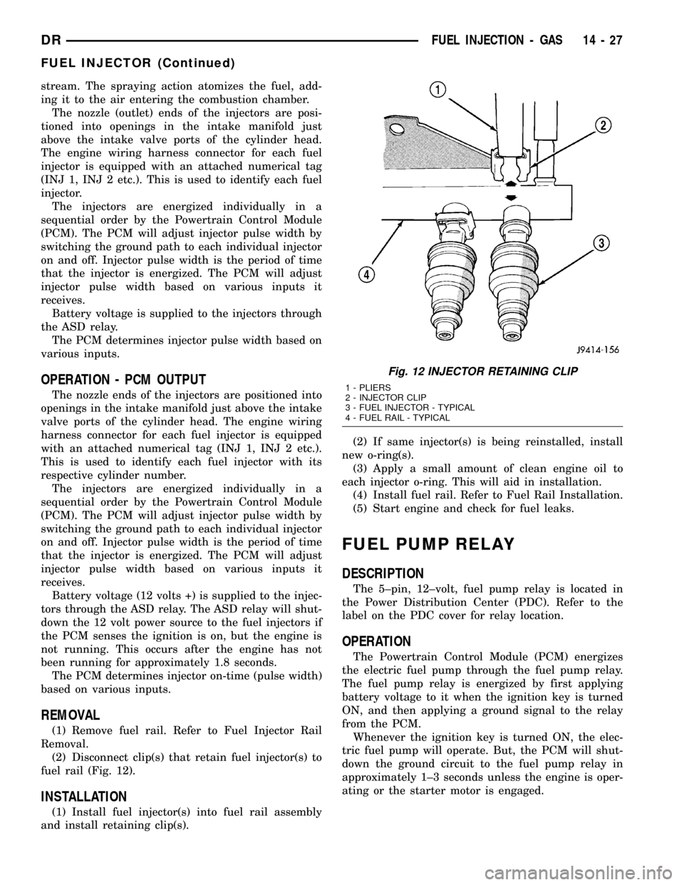
(2) Disconnect clip(s) that retain fuel injector(s) to
fuel rail (Fig. 12).
INSTALLATION
(1) Install fuel injector(s) into fuel rail assembly
and install retaining clip(s).(2) If same injector(s) is being reinstalled, install
new o-ring(s).
(3) Apply a small amount of clean engine oil to
each injector o-ring. This will aid in installation.
(4) Install fuel rail. Refer to Fuel Rail Installation.
(5) Start engine and check for fuel leaks.
FUEL PUMP RELAY
DESCRIPTION
The 5±pin, 12±volt, fuel pump relay is located in
the Power Distribution Center (PDC). Refer to the
label on the PDC cover for relay location.
OPERATION
The Powertrain Control Module (PCM) energizes
the electric fuel pump through the fuel pump relay.
The fuel pump relay is energized by first applying
battery voltage to it when the ignition key is turned
ON, and then applying a ground signal to the relay
from the PCM.
Whenever the ignition key is turned ON, the elec-
tric fuel pump will operate. But, the PCM will shut-
down the ground circuit to the fuel pump relay in
approximately 1±3 seconds unless the engine is oper-
ating or the starter motor is engaged.
Fig. 12 INJECTOR RETAINING CLIP
1 - PLIERS
2 - INJECTOR CLIP
3 - FUEL INJECTOR - TYPICAL
4 - FUEL RAIL - TYPICAL
DRFUEL INJECTION - GAS 14 - 27
FUEL INJECTOR (Continued)