Battery starter DODGE RAM 1500 1998 2.G Service Manual
[x] Cancel search | Manufacturer: DODGE, Model Year: 1998, Model line: RAM 1500, Model: DODGE RAM 1500 1998 2.GPages: 2627
Page 1406 of 2627
DIAGNOSIS AND TESTING
DIAGNOSIS AND TESTING - ENGINE
DIAGNOSIS - INTRODUCTION
Engine diagnosis is helpful in determining the
causes of malfunctions not detected and remedied by
routine maintenance.
These malfunctions may be classified as either per-
formance (e.g., engine idles rough and stalls) or
mechanical (e.g., a strange noise).
(Refer to 9 - ENGINE - DIAGNOSIS AND TEST-
ING) - PERFORMANCE and (Refer to 9 - ENGINE -
DIAGNOSIS AND TESTING)ÐMECHANICAL for
possible causes and corrections of malfunctions.
(Refer to 14 - FUEL SYSTEM/FUEL DELIVERY -
DIAGNOSIS AND TESTING) and (Refer to 14 -
FUEL SYSTEM/FUEL INJECTION - DIAGNOSIS
AND TESTING) for the fuel system diagnosis.Additional tests and diagnostic procedures may be
necessary for specific engine malfunctions that can
not be isolated with the Service Diagnosis charts.
Information concerning additional tests and diagno-
sis is provided within the following diagnosis:
²Cylinder Compression Pressure Test (Refer to 9 -
ENGINE - DIAGNOSIS AND TESTING).
²Cylinder Combustion Pressure Leakage Test
(Refer to 9 - ENGINE - DIAGNOSIS AND TEST-
ING).
²Engine Cylinder Head Gasket Failure Diagnosis
(Refer to 9 - ENGINE/CYLINDER HEAD - DIAGNO-
SIS AND TESTING).
²Intake Manifold Leakage Diagnosis (Refer to 9 -
ENGINE/MANIFOLDS/INTAKE MANIFOLD -
DIAGNOSIS AND TESTING).
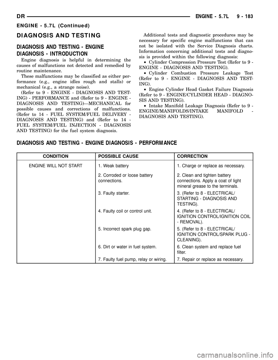
DIAGNOSIS AND TESTING - ENGINE DIAGNOSIS - PERFORMANCE
CONDITION POSSIBLE CAUSE CORRECTION
ENGINE WILL NOT START 1. Weak battery 1. Charge or replace as necessary.
2. Corroded or loose battery
connections.2. Clean and tighten battery
connections. Apply a coat of light
mineral grease to the terminals.
3. Faulty starter. 3. (Refer to 8 - ELECTRICAL/
STARTING - DIAGNOSIS AND
TESTING).
4. Faulty coil or control unit. 4. (Refer to 8 - ELECTRICAL/
IGNITION CONTROL/IGNITION COIL
- REMOVAL).
5. Incorrect spark plug gap. 5. (Refer to 8 - ELECTRICAL/
IGNITION CONTROL/SPARK PLUG -
CLEANING).
6. Dirt or water in fuel system. 6. Clean system and replace fuel
filter.
7. Faulty fuel pump, relay or wiring. 7. Repair or replace as necessary.
DRENGINE - 5.7L 9 - 183
ENGINE - 5.7L (Continued)
Page 1409 of 2627
DIAGNOSIS AND TESTING - CYLINDER
COMPRESSION PRESSURE
The results of a cylinder compression pressure test
can be utilized to diagnose several engine malfunc-
tions.
Ensure the battery is completely charged and the
engine starter motor is in good operating condition.
Otherwise the indicated compression pressures may
not be valid for diagnosis purposes.
(1) Clean the spark plug recesses with compressed
air.
(2) Remove the spark plugs.
(3) Disable the fuel system (Refer to 14 - FUEL
SYSTEM/FUEL DELIVERY - DESCRIPTION).
(4) Remove the ASD relay (Refer to 8 - ELECTRI-
CAL/IGNITION CONTROL/AUTO SHUT DOWN
RELAY - REMOVAL).
(5) Insert a compression pressure gauge and rotate
the engine with the engine starter motor for three
revolutions.
(6) Record the compression pressure on the 3rd
revolution. Continue the test for the remaining cylin-
ders.
(7) (Refer to 9 - ENGINE - SPECIFICATIONS) for
the correct engine compression pressures.
DIAGNOSIS AND TESTING - CYLINDER
COMBUSTION PRESSURE LEAKAGE
The combustion pressure leakage test provides an
accurate means for determining engine condition.
Combustion pressure leakage testing will detect:
²Exhaust and intake valve leaks (improper seat-
ing).²Leaks between adjacent cylinders or into water
jacket.
²Any causes for combustion/compression pressure
loss.
(1) Check the coolant level and fill as required. DO
NOT install the radiator cap.
(2) Start and operate the engine until it attains
normal operating temperature, then turn the engine
OFF.
(3) Remove the spark plugs.
(4) Remove the oil filler cap.
(5) Remove the air cleaner hose.
(6) Calibrate the tester according to the manufac-
turer's instructions. The shop air source for testing
should maintain 483 kPa (70 psi) minimum, 1,379
kPa (200 psi) maximum and 552 kPa (80 psi) recom-
mended.
(7) Perform the test procedures on each cylinder
according to the tester manufacturer's instructions.
Set piston of cylinder to be tested at TDC compres-
sion,While testing, listen for pressurized air escaping
through the throttle body, tailpipe and oil filler cap
opening. Check for bubbles in the radiator coolant.
All gauge pressure indications should be equal,
with no more than 25% leakage.
FOR EXAMPLE:At 552 kPa (80 psi) input pres-
sure, a minimum of 414 kPa (60 psi) should be main-
tained in the cylinder.
Refer to CYLINDER COMBUSTION PRESSURE
LEAKAGE DIAGNOSIS CHART.
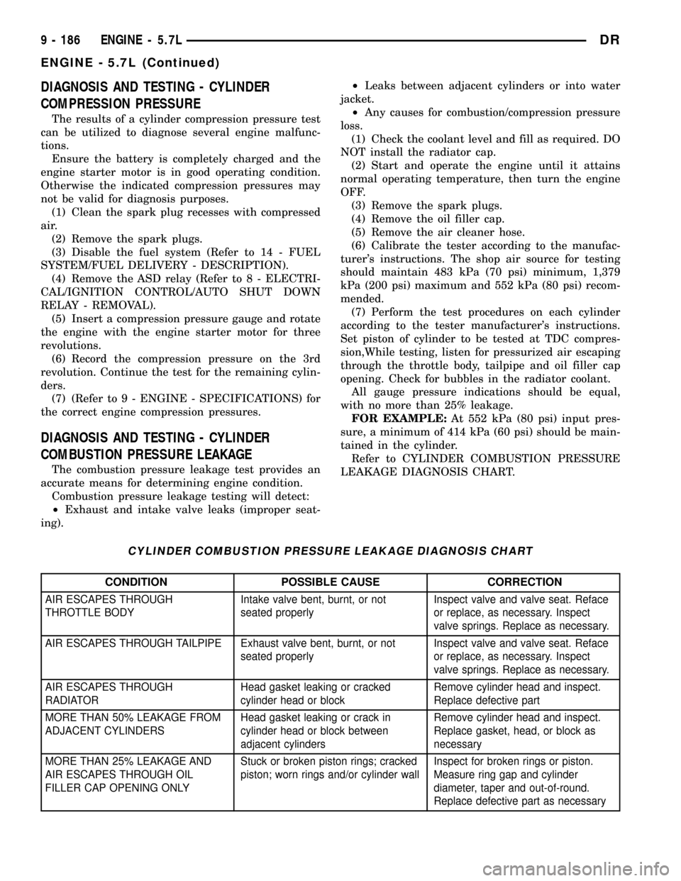
CYLINDER COMBUSTION PRESSURE LEAKAGE DIAGNOSIS CHART
CONDITION POSSIBLE CAUSE CORRECTION
AIR ESCAPES THROUGH
THROTTLE BODYIntake valve bent, burnt, or not
seated properlyInspect valve and valve seat. Reface
or replace, as necessary. Inspect
valve springs. Replace as necessary.
AIR ESCAPES THROUGH TAILPIPE Exhaust valve bent, burnt, or not
seated properlyInspect valve and valve seat. Reface
or replace, as necessary. Inspect
valve springs. Replace as necessary.
AIR ESCAPES THROUGH
RADIATORHead gasket leaking or cracked
cylinder head or blockRemove cylinder head and inspect.
Replace defective part
MORE THAN 50% LEAKAGE FROM
ADJACENT CYLINDERSHead gasket leaking or crack in
cylinder head or block between
adjacent cylindersRemove cylinder head and inspect.
Replace gasket, head, or block as
necessary
MORE THAN 25% LEAKAGE AND
AIR ESCAPES THROUGH OIL
FILLER CAP OPENING ONLYStuck or broken piston rings; cracked
piston; worn rings and/or cylinder wallInspect for broken rings or piston.
Measure ring gap and cylinder
diameter, taper and out-of-round.
Replace defective part as necessary
9 - 186 ENGINE - 5.7LDR
ENGINE - 5.7L (Continued)
Page 1413 of 2627
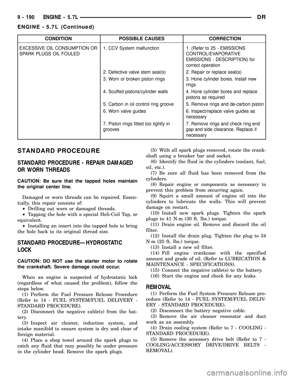
CONDITION POSSIBLE CAUSES CORRECTION
EXCESSIVE OIL CONSUMPTION OR
SPARK PLUGS OIL FOULED1. CCV System malfunction 1. (Refer to 25 - EMISSIONS
CONTROL/EVAPORATIVE
EMISSIONS - DESCRIPTION) for
correct operation
2. Defective valve stem seal(s) 2. Repair or replace seal(s)
3. Worn or broken piston rings 3. Hone cylinder bores. Install new
rings
4. Scuffed pistons/cylinder walls 4. Hone cylinder bores and replace
pistons as required
5. Carbon in oil control ring groove 5. Remove rings and de-carbon piston
6. Worn valve guides 6. Inspect/replace valve guides as
necessary
7. Piston rings fitted too tightly in
grooves7. Remove rings and check ring end
gap and side clearance. Replace if
necessary
STANDARD PROCEDURE
STANDARD PROCEDURE - REPAIR DAMAGED
OR WORN THREADS
CAUTION: Be sure that the tapped holes maintain
the original center line.
Damaged or worn threads can be repaired. Essen-
tially, this repair consists of:
²Drilling out worn or damaged threads.
²Tapping the hole with a special Heli-Coil Tap, or
equivalent.
²Installing an insert into the tapped hole to bring
the hole back to its original thread size.
STANDARD PROCEDUREÐHYDROSTATIC
LOCK
CAUTION: DO NOT use the starter motor to rotate
the crankshaft. Severe damage could occur.
When an engine is suspected of hydrostatic lock
(regardless of what caused the problem), follow the
steps below.
(1) Perform the Fuel Pressure Release Procedure
(Refer to 14 - FUEL SYSTEM/FUEL DELIVERY -
STANDARD PROCEDURE).
(2) Disconnect the negative cable(s) from the bat-
tery.
(3) Inspect air cleaner, induction system, and
intake manifold to ensure system is dry and clear of
foreign material.
(4) Place a shop towel around the spark plugs to
catch any fluid that may possibly be under pressure
in the cylinder head. Remove the spark plugs.(5) With all spark plugs removed, rotate the crank-
shaft using a breaker bar and socket.
(6) Identify the fluid in the cylinders (coolant, fuel,
oil, etc.).
(7) Be sure all fluid has been removed from the
cylinders.
(8) Repair engine or components as necessary to
prevent this problem from occurring again.
(9) Squirt a small amount of engine oil into the
cylinders to lubricate the walls. This will prevent
damage on restart.
(10) Install new spark plugs. Tighten the spark
plugs to 41 N´m (30 ft. lbs.) torque.
(11) Drain engine oil. Remove and discard the oil
filter.
(12) Install the drain plug. Tighten the plug to 34
N´m (25 ft. lbs.) torque.
(13) Install a new oil filter.
(14) Fill engine crankcase with the specified
amount and grade of oil. (Refer to LUBRICATION &
MAINTENANCE - SPECIFICATIONS).
(15) Connect the negative cable(s) to the battery.
(16) Start the engine and check for any leaks.
REMOVAL
(1) Perform the Fuel System Pressure Release pro-
cedure (Refer to 14 - FUEL SYSTEM/FUEL DELIV-
ERY - STANDARD PROCEDURE).
(2) Disconnect the battery negative cable.
(3) Remove the air cleaner resonator and duct
work as an assembly.
(4) Drain cooling system (Refer to 7 - COOLING -
STANDARD PROCEDURE).
(5) Remove the accessory drive belt (Refer to 7 -
COOLING/ACCESSORY DRIVE/DRIVE BELTS -
REMOVAL).
9 - 190 ENGINE - 5.7LDR
ENGINE - 5.7L (Continued)
Page 1464 of 2627
(10) Drain engine oil. Remove and discard the oil
filter (Refer to 9 - ENGINE/LUBRICATION/OIL FIL-
TER - REMOVAL).
(11) Install the drain plug. Tighten the plug to 50
N´m (37 ft. lbs.) torque.
(12) Install a new oil filter (Refer to 9 - ENGINE/
LUBRICATION/OIL FILTER - INSTALLATION).
(13) Fill engine crankcase with the specified
amount and grade of oil (Refer to LUBRICATION &
MAINTENANCE/FLUID TYPES - SPECIFICA-
TIONS).
(14) Connect the negative cable(s) to the battery.
(15) Start the engine and check for any leaks.
REMOVAL
REMOVAL - ENGINE
(1) Disconnect both battery negative cables.
(2) Disconnect engine grid heater harness at grid
heater relays.
(3) Disconnect electrical connections from rear of
alternator.
(4) Recover A/C refrigerant. (Refer to 24 - HEAT-
ING & AIR CONDITIONING/PLUMBING - STAN-
DARD PROCEDURE).
(5) Raise vehicle on a hoist.
(6) Drain engine coolant (Refer to 7 - COOLING -
STANDARD PROCEDURE).
(7) Remove engine oil drain plug and drain engine
oil.
(8) Reinstall drain plug. Tighten to 50N´m (37 ft.
lbs.) torque.
(9) Lower the vehicle.
(10) Remove fan/drive assembly. Refer to Section 7
± Fan/Drive Removal
(11) Remove radiator upper hose.
(12) Remove upper fan shroud mounting bolts.
(13) Disconnect the coolant recovery bottle hose
from the radiator fill neck and remove bottle.
(14) Using a 36mm wrench, remove viscous fan/
drive assembly. (Refer to 7 - COOLING/ENGINE/RA-
DIATOR FAN - REMOVAL).
(15) Remove cooling fan and shroud together.
(16) Disconnect heater core supply and return
hoses from the cylinder head fitting and coolant pipe.
(17) Raise vehicle on a hoist.
(18) Remove transmission and transfer case (if
equipped).
(19) Disconnect exhaust pipe from turbocharger
extension pipe.
(20) Disconnect engine harness to vehicle harness
connectors.
(21) Remove starter motor (Refer to 8 - ELECTRI-
CAL/STARTING/STARTER MOTOR - REMOVAL).(22) Remove flywheel/flexplate.
(23) Remove transmission adapter
(24) Disconnect A/C suction/discharge hose from
the rear of the A/C compressor.
(25) Lower vehicle.
(26) Disconnect lower radiator hose from radiator
outlet.
(27) Automatic transmission models:
(28) Disconnect transmission oil cooler lines from
in front of radiator using special tool #6931
(29) Remove radiator. (Refer to 7 - COOLING/EN-
GINE/RADIATOR - REMOVAL).
(30) If A/C equipped, disconnect A/C condenser
refrigerant lines.
(31) Disconnect charge air cooler piping.
(32) Remove charge air cooler mounting bolts.
(33) Remove charge air cooler (and A/C condenser
if equipped) from vehicle.
(34) Remove damper and speed indicator ring from
front of engine.
(35) Disconnect engine block heater connector.
(36) Disconnect A/C compressor and pressure sen-
sor electrical connectors.
(37) Remove the passenger battery ground cable
from the engine block. Remove the driver side bat-
tery ground cable from the engine block.
(38) Remove power steering pump from engine by
removing 3 bolts.
(39) Remove accelerator linkage cover.
(40) Disconnect cables from on-engine APPS.
(41) Disconnect the ECM power connector.
(42) Disconnect the ECM ground wire from the
hydroform screw.
(43) Disconnect the fuel supply and return hoses.
(44) Remove the cylinder head cover. (Refer to 9 -
ENGINE/CYLINDER HEAD/CYLINDER HEAD
COVER(S) - REMOVAL).
(45) Disconnect the 3 injector harness connectors
at the rocker housing. Disconnect the wire harnesses
from the injectors.
(46) Remove the rear engine lift bracket.
(47) Remove cylinder #4, #5, and #6 intake and
exhaust rocker arms, pedestals, and push tubes. Note
the original location for re-assembly.
(48) Loosen #6 fuel line shield bolts and rotate
shield out of the way.
(49) Remove cylinder #5 and #6 high pressure fuel
lines. Remove the fuel connector tube nut and fuel
connector tube. Remove cylinder #5 and #6 fuel injec-
tor.
(50) Remove rocker housing.
DRENGINE 5.9L DIESEL 9 - 241
ENGINE 5.9L DIESEL (Continued)
Page 1466 of 2627
(8) Replace injector o-ring and sealing washer on
injectors #5 and #6. Install injectors and torque using
the following steps:
²Step 1ÐInstall injector hold-down capscrews
and torque to 5 N´m (44 in. lbs.) torque.
²Step 2ÐLoosen injector hold-down capscrews.
²Step 3ÐInstall HPC connector tube and nut.
Torque nut to 15 N´m (11 ft. lbs.) torque.
²Step 4ÐTorque injector hold-down capscrews to
10 N´m (89 in. lbs.) torque.
²Step 5ÐTorque HPC connector tube nut to 50
N´m (37 ft. lbs.) torque.
(9) Install #5 and #6 high pressure fuel lines. Fol-
low correct torque sequence per section 14. Torque
fuel line fittings to 30 N-m (22 ft-lb). Torque brace
capscrew to 24 N-m (18 ft-lb).
(10) Install rear engine lift bracket. Torque to 77
N-m (57 ft-lb).
(11) Install push tubes, rocker arms, and pedestals
for cylinders #4, #5, and #6. Torque the mounting
bolts to 36 N-m (27 ft-lbs).
(12) Reset valve lash on cylinders #4, #5, and #6.
Torque adjusting nuts to 24 N-m (18 ft-lbs).
(13) Install cylinder head cover. Torque to 24 N-m
(18 ft-lbs).(Refer to 9 - ENGINE/CYLINDER HEAD -
INSTALLATION).
(14) Connect breather tube and lube oil drain tube
to breather housing cover. Install breather housing.
Torque capscrews to 24 N-m (18 ft-lbs)
(15) Connect fuel supply and return hoses.
(16) Connect ECM ground to hydroform screw.
Connect ECM power connector.
(17) Install the APPS cable(s) to the APPS. Install
the throttle linkage cover.
(18) Install the power steering pump.
(19) Install the damper and speed indicator ring.
Torque to 40 N-m (30 ft-lb) plus 60 degrees.
(20) Connect the engine block heater connection.
(21) Connect the A/C compressor and pressure sen-
sor connectors
(22) Install the charge air cooler and a/c condenser
(if equipped). Install and tighten the charge air
cooler mounting bolts to 2 N-m (17 in-lbs).
(23) Connect the charge air cooler piping. Torque
all clamps to 8 N-m (72 in-lbs).
(24) Connect the a/c refrigerant lines to the a/c
condenser (if equipped).
(25) Install the radiator upper support panel.
(26) Install radiator.
(27) Connect the transmission quick-connect oil
cooler lines.(28) Raise vehicle.
(29) Connect a/c compressor suction/discharge hose
(if equipped).
(30) Install the radiator lower hose and clamps.
(31) Install the battery negative cables to the
engine block on the driver and passenger side.
(32) Install the transmission adapter with a new
camshaft rectangular ring seal. Torque to 77 N-m (57
ft-lb).
(33) Install the flywheel/flexplate. Torque to 137
N-m (101 ft-lb).
(34) Install the starter motor. Torque to 43 N-m
(32 ft-lb). (Refer to 8 - ELECTRICAL/STARTING/
STARTER MOTOR - INSTALLATION).
(35) Connect engine to vehicle harness connectors.
(36) Install transmission and transfer case (if
equipped).
(37) Connect the exhaust pipe to the turbocharger
elbow.
(38) Connect the transmission auxiliary oil cooler
lines (if equipped).
(39) Lower the vehicle.
(40) Connect the heater core supply and return
hoses.
(41) Install the cooling fan and upper fan shroud
at the same time. (Refer to 7 - COOLING/ENGINE/
RADIATOR FAN - INSTALLATION).
(42) Install the coolant recovery bottle.
(43) Install the windshield washer bottle.
(44) Install the upper radiator hose and clamps.
(45) Raise vehicle.
(46) Connect electronically controlled fan drive
wire harness. Install lower radiator fan shroud.
(47) Change oil filter and install new engine oil.
(48) Fill the cooling system with coolant. (Refer to
7 - COOLING - STANDARD PROCEDURE).
(49) Connect grid heater harness at grid heater
relays.
(50) Connect electrical connections to rear of alter-
nator.
(51) Start the engine and inspect for engine oil,
coolant, and fuel leaks.
INSTALLATIONÐCRANKCASE BREATHER
(1) Install a new o-ring onto the breather element.
(2) Lubricate o-ring and install into cylinder head
cover. Torque capscrews to 10 N´m (89 in. lbs.).
(3) Connect breather tube and lube oil drain tube.
(4) Install breather cover (Fig. 4). Torque to 24
N´m (18 ft. lbs.)
(5) Install oil fill cap.
DRENGINE 5.9L DIESEL 9 - 243
ENGINE 5.9L DIESEL (Continued)
Page 1500 of 2627
(7) Install the flywheel or converter drive plate.
Tighten the bolts to 137 N´m (101 ft. lbs.) torque.
(8) Install the clutch cover and disc (if equipped)
(Refer to 6 - CLUTCH/CLUTCH DISC - INSTALLA-
TION).
(9) Install the transmission and transfer case (if
equipped).
(10) Lower vehicle.
(11) Connect battery negative cables.
(12) Check engine oil level and adjust, if necessary.
(13) Start engine and check for oil leaks.
CRANKSHAFT REAR OIL SEAL
RETAINER
REMOVAL
(1) Disconnect the battery negative cables.
(2) Raise vehicle on hoist.
(3) Remove the oil pan drain plug and drain the
engine oil. Re-install plug and torque to 50 N´m (44
ft. lbs.) torque.
(4) Remove transmission and transfer case (if
equipped) from vehicle.
(5)
Remove flywheel or torque converter drive plate.
(6) Disconnect starter cables from starter motor.
(7) Remove starter motor (Refer to 8 - ELECTRI-
CAL/STARTING/STARTER MOTOR - REMOVAL)
and transmission adapter plate assembly.
(8) Remove four (4) oil pan rear bolts. Slide a
feeler gauge between the seal retainer and oil pan
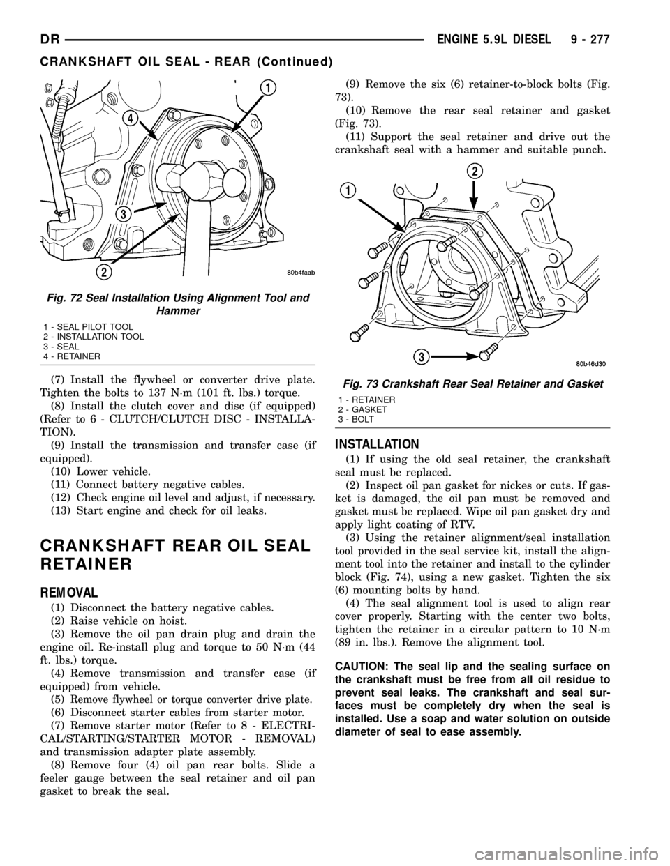
gasket to break the seal.(9) Remove the six (6) retainer-to-block bolts (Fig.
73).
(10) Remove the rear seal retainer and gasket
(Fig. 73).
(11) Support the seal retainer and drive out the
crankshaft seal with a hammer and suitable punch.
INSTALLATION
(1) If using the old seal retainer, the crankshaft
seal must be replaced.
(2) Inspect oil pan gasket for nickes or cuts. If gas-
ket is damaged, the oil pan must be removed and
gasket must be replaced. Wipe oil pan gasket dry and
apply light coating of RTV.
(3) Using the retainer alignment/seal installation
tool provided in the seal service kit, install the align-
ment tool into the retainer and install to the cylinder
block (Fig. 74), using a new gasket. Tighten the six
(6) mounting bolts by hand.
(4) The seal alignment tool is used to align rear
cover properly. Starting with the center two bolts,
tighten the retainer in a circular pattern to 10 N´m
(89 in. lbs.). Remove the alignment tool.
CAUTION: The seal lip and the sealing surface on
the crankshaft must be free from all oil residue to
prevent seal leaks. The crankshaft and seal sur-
faces must be completely dry when the seal is
installed. Use a soap and water solution on outside
diameter of seal to ease assembly.
Fig. 72 Seal Installation Using Alignment Tool and
Hammer
1 - SEAL PILOT TOOL
2 - INSTALLATION TOOL
3 - SEAL
4 - RETAINER
Fig. 73 Crankshaft Rear Seal Retainer and Gasket
1 - RETAINER
2 - GASKET
3 - BOLT
DRENGINE 5.9L DIESEL 9 - 277
CRANKSHAFT OIL SEAL - REAR (Continued)
Page 1501 of 2627
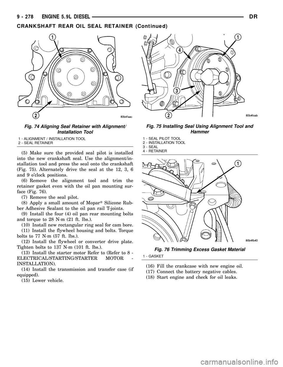
(5) Make sure the provided seal pilot is installed
into the new crankshaft seal. Use the alignment/in-
stallation tool and press the seal onto the crankshaft
(Fig. 75). Alternately drive the seal at the 12, 3, 6
and 9 o'clock positions.
(6) Remove the alignment tool and trim the
retainer gasket even with the oil pan mounting sur-
face (Fig. 76).
(7) Remove the seal pilot.
(8) Apply a small amount of MopartSilicone Rub-
ber Adhesive Sealant to the oil pan rail T-joints.
(9) Install the four (4) oil pan rear mounting bolts
and torque to 28 N´m (21 ft. lbs.).
(10) Install new rectangular ring seal for cam bore.
(11) Install the flywheel housing and bolts. Torque
bolts to 77 N´m (57 ft. lbs.).
(12) Install the flywheel or converter drive plate.
Tighten bolts to 137 N´m (101 ft. lbs.).
(13) Install the starter motor Refer to (Refer to 8 -
ELECTRICAL/STARTING/STARTER MOTOR -
INSTALLATION).
(14) Install the transmission and transfer case (if
equipped).
(15) Lower vehicle.(16) Fill the crankcase with new engine oil.
(17) Connect the battery negative cables.
(18) Start engine and check for oil leaks.
Fig. 74 Aligning Seal Retainer with Alignment/
Installation Tool
1 - ALIGNMENT / INSTALLATION TOOL
2 - SEAL RETAINER
Fig. 75 Installing Seal Using Alignment Tool and
Hammer
1 - SEAL PILOT TOOL
2 - INSTALLATION TOOL
3 - SEAL
4 - RETAINER
Fig. 76 Trimming Excess Gasket Material
1 - GASKET
9 - 278 ENGINE 5.9L DIESELDR
CRANKSHAFT REAR OIL SEAL RETAINER (Continued)
Page 1516 of 2627
OIL COOLER & LINES
CLEANING
CLEANING AND INSPECTION
Clean the sealing surfaces.
Apply 483 kPa (70 psi) air pressure to the element
to check for leaks. If the element leaks, replace the
element.
OIL FILTER
REMOVAL
(1) Clean the area around the oil filter head.
Remove the filter from below using a cap-style filter
wrench.
(2) Clean the gasket surface of the filter head. The
filter canister O-Ring seal can stick on the filter
head. Make sure it is removed.
INSTALLATION
(1) Fill the oil filter element with clean oil before
installation. Use the same type oil that will be used
in the engine.
(2) Apply a light film of lubricating oil to the seal-
ing surface before installing the filter.
CAUTION: Mechanical over-tightening may distort
the threads or damage the filter element seal.
(3) Install the filter until it contacts the sealing
surface of the oil filter adapter. Tighten filter an
additional
1¤2turn.
OIL PAN
REMOVAL
(1) Disconnect the battery negative cables.
(2) Install engine support fixture # 8534.
(3) Raise vehicle on hoist.
(4) Disconnect starter cables from starter motor.
(5) Remove transmission and transfer case (if
equipped).
(6) Remove flywheel or flexplate.
(7) Remove starter motor (Refer to 8 - ELECTRI-
CAL/STARTING/STARTER MOTOR - REMOVAL)
and transmission adapter plate assembly.
WARNING: HOT OIL CAN CAUSE PERSONAL
INJURY.
(8) Drain the engine oil (Refer to 9 - ENGINE/LU-
BRICATION/OIL - STANDARD PROCEDURE).(9) Install the oil pan drain plug if sealing surface
is not damaged and tighten to 50 N´m (37 ft. lbs.)
torque.
(10) Remove oil pan bolts, break the pan to block
seal, and lower pan slightly and remove oil suction
tube fasteners.
(11) Remove oil pan and suction tube.
CLEANING
Remove all gasket material from the oil pan and
cylinder block sealing surfaces. Extra effort may be
required around T-joint areas. Clean oil pan and
flush suction tube with a suitable solvent.
INSPECTION
Inspect the oil pan, suction tube, and tube braces
for cracks and damage. Replace any defective compo-
nent. Inspect the oil drain plug and drain hole
threads. Inspect the oil pan sealing surface for
straightness. Repair any minor imperfections with a
ball-peen hammer. Do not attempt to repair an oil
pan by welding.
INSTALLATION
(1) Fill the T-joint between the pan rail/gear hous-
ing and pan rail/rear seal retainer with sealant. Use
MopartSilicone Rubber Adhesive Sealant or equiva-
lent.
(2) Place suction tube in oil pan and guide them
into place. Using a new tube to block gasket, install
and tighten the suction tube bolts by hand. Starting
with the oil pump inlet bolts, tighten the bolts to 24
N´m (18 ft. lbs.) torque. Tighten the remaining tube
brace bolts to 43 N´m (32 ft. lbs.) torque.
(3) Starting in the center and working outward,
tighten the oil pan bolts to 28 N´m (21 ft. lbs.)
torque.
(4) Install the flywheel housing assembly with the
starter motor attached and tighten bolts to 77 N´m
(57 ft. lbs.) torque.
(5) Connect starter motor cables.
(6) Install the flywheel or flexplate. Torque to 137
N´m (101 ft. lbs.).
(7) Install transmission and transfer case (if
equipped).
(8) Lower vehicle.
(9) Remove the engine support fixture # 8534.
(10) Install battery negative cables.
(11) Fill the crankcase with new engine oil.
(12) Start engine and check for leaks. Stop engine,
check oil level, and adjust, if necessary.
DRENGINE 5.9L DIESEL 9 - 293
Page 1596 of 2627
stream. The spraying action atomizes the fuel, add-
ing it to the air entering the combustion chamber.
The nozzle (outlet) ends of the injectors are posi-
tioned into openings in the intake manifold just
above the intake valve ports of the cylinder head.
The engine wiring harness connector for each fuel
injector is equipped with an attached numerical tag
(INJ 1, INJ 2 etc.). This is used to identify each fuel
injector.
The injectors are energized individually in a
sequential order by the Powertrain Control Module
(PCM). The PCM will adjust injector pulse width by
switching the ground path to each individual injector
on and off. Injector pulse width is the period of time
that the injector is energized. The PCM will adjust
injector pulse width based on various inputs it
receives.
Battery voltage is supplied to the injectors through
the ASD relay.
The PCM determines injector pulse width based on
various inputs.
OPERATION - PCM OUTPUT
The nozzle ends of the injectors are positioned into
openings in the intake manifold just above the intake
valve ports of the cylinder head. The engine wiring
harness connector for each fuel injector is equipped
with an attached numerical tag (INJ 1, INJ 2 etc.).
This is used to identify each fuel injector with its
respective cylinder number.
The injectors are energized individually in a
sequential order by the Powertrain Control Module
(PCM). The PCM will adjust injector pulse width by
switching the ground path to each individual injector
on and off. Injector pulse width is the period of time
that the injector is energized. The PCM will adjust
injector pulse width based on various inputs it
receives.
Battery voltage (12 volts +) is supplied to the injec-
tors through the ASD relay. The ASD relay will shut-
down the 12 volt power source to the fuel injectors if
the PCM senses the ignition is on, but the engine is
not running. This occurs after the engine has not
been running for approximately 1.8 seconds.
The PCM determines injector on-time (pulse width)
based on various inputs.
REMOVAL
(1) Remove fuel rail. Refer to Fuel Injector Rail
Removal.
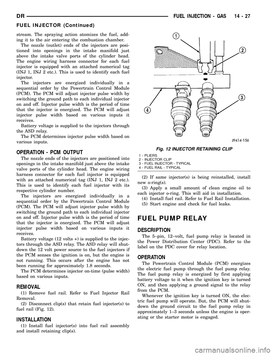
(2) Disconnect clip(s) that retain fuel injector(s) to
fuel rail (Fig. 12).
INSTALLATION
(1) Install fuel injector(s) into fuel rail assembly
and install retaining clip(s).(2) If same injector(s) is being reinstalled, install
new o-ring(s).
(3) Apply a small amount of clean engine oil to
each injector o-ring. This will aid in installation.
(4) Install fuel rail. Refer to Fuel Rail Installation.
(5) Start engine and check for fuel leaks.
FUEL PUMP RELAY
DESCRIPTION
The 5±pin, 12±volt, fuel pump relay is located in
the Power Distribution Center (PDC). Refer to the
label on the PDC cover for relay location.
OPERATION
The Powertrain Control Module (PCM) energizes
the electric fuel pump through the fuel pump relay.
The fuel pump relay is energized by first applying
battery voltage to it when the ignition key is turned
ON, and then applying a ground signal to the relay
from the PCM.
Whenever the ignition key is turned ON, the elec-
tric fuel pump will operate. But, the PCM will shut-
down the ground circuit to the fuel pump relay in
approximately 1±3 seconds unless the engine is oper-
ating or the starter motor is engaged.
Fig. 12 INJECTOR RETAINING CLIP
1 - PLIERS
2 - INJECTOR CLIP
3 - FUEL INJECTOR - TYPICAL
4 - FUEL RAIL - TYPICAL
DRFUEL INJECTION - GAS 14 - 27
FUEL INJECTOR (Continued)
Page 1861 of 2627
STANDARD PROCEDURE - ALUMINUM
THREAD REPAIR
Damaged or worn threads in the aluminum trans-
mission case and valve body can be repaired by the
use of Heli-CoilsŸ, or equivalent. This repair con-
sists of drilling out the worn-out damaged threads.
Then tap the hole with a special Heli-CoilŸ tap, or
equivalent, and installing a Heli-CoilŸ insert, or
equivalent, into the hole. This brings the hole back to
its original thread size.
Heli-CoilŸ, or equivalent, tools and inserts are
readily available from most automotive parts suppli-
ers.
REMOVAL
NOTE: The overdrive unit can be removed and ser-
viced separately. It is not necessary to remove the
entire transmission assembly to perform overdrive
unit repairs.
(1) Disconnect battery negative cable.
(2) Raise vehicle.
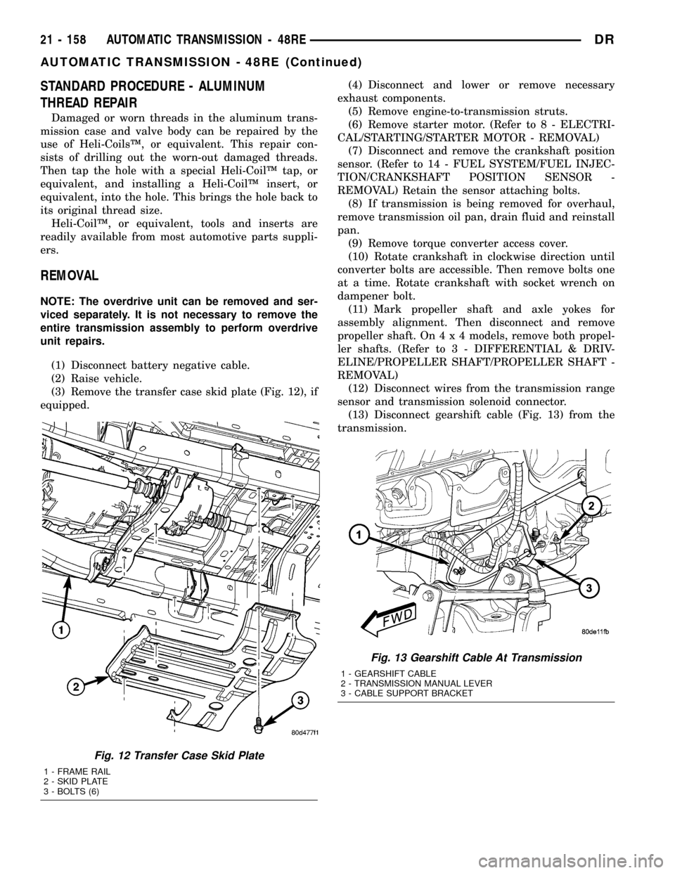
(3) Remove the transfer case skid plate (Fig. 12), if
equipped.(4) Disconnect and lower or remove necessary
exhaust components.
(5) Remove engine-to-transmission struts.
(6) Remove starter motor. (Refer to 8 - ELECTRI-
CAL/STARTING/STARTER MOTOR - REMOVAL)
(7) Disconnect and remove the crankshaft position
sensor. (Refer to 14 - FUEL SYSTEM/FUEL INJEC-
TION/CRANKSHAFT POSITION SENSOR -
REMOVAL) Retain the sensor attaching bolts.
(8) If transmission is being removed for overhaul,
remove transmission oil pan, drain fluid and reinstall
pan.
(9) Remove torque converter access cover.
(10) Rotate crankshaft in clockwise direction until
converter bolts are accessible. Then remove bolts one
at a time. Rotate crankshaft with socket wrench on
dampener bolt.
(11) Mark propeller shaft and axle yokes for
assembly alignment. Then disconnect and remove
propeller shaft. On4x4models, remove both propel-
ler shafts. (Refer to 3 - DIFFERENTIAL & DRIV-
ELINE/PROPELLER SHAFT/PROPELLER SHAFT -
REMOVAL)
(12) Disconnect wires from the transmission range
sensor and transmission solenoid connector.
(13) Disconnect gearshift cable (Fig. 13) from the
transmission.
Fig. 12 Transfer Case Skid Plate
1 - FRAME RAIL
2 - SKID PLATE
3 - BOLTS (6)
Fig. 13 Gearshift Cable At Transmission
1 - GEARSHIFT CABLE
2 - TRANSMISSION MANUAL LEVER
3 - CABLE SUPPORT BRACKET
21 - 158 AUTOMATIC TRANSMISSION - 48REDR
AUTOMATIC TRANSMISSION - 48RE (Continued)