Window DODGE RAM 1500 1998 2.G Repair Manual
[x] Cancel search | Manufacturer: DODGE, Model Year: 1998, Model line: RAM 1500, Model: DODGE RAM 1500 1998 2.GPages: 2627
Page 1135 of 2627
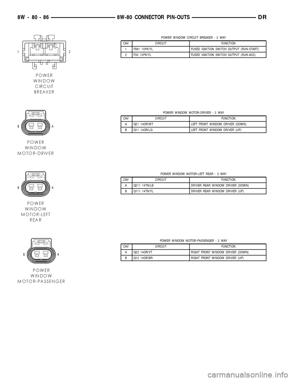
POWER WINDOW CIRCUIT BREAKER-2WAY
CAV CIRCUIT FUNCTION
1 F991 10PK/YL FUSED IGNITION SWITCH OUTPUT (RUN-START)
2 F30 12PK/YL FUSED IGNITION SWITCH OUTPUT (RUN-ACC)
POWER WINDOW MOTOR-DRIVER-2WAY
CAV CIRCUIT FUNCTION
A Q21 14OR/WT LEFT FRONT WINDOW DRIVER (DOWN)
B Q11 14OR/LG LEFT FRONT WINDOW DRIVER (UP)
POWER WINDOW MOTOR-LEFT REAR-2WAY
CAV CIRCUIT FUNCTION
A Q211 14TN/LB DRIVER REAR WINDOW DRIVER (DOWN)
B Q111 14TN/YL DRIVER REAR WINDOW DRIVER (UP)
POWER WINDOW MOTOR-PASSENGER-2WAY
CAV CIRCUIT FUNCTION
A Q22 14OR/VT RIGHT FRONT WINDOW DRIVER (DOWN)
B Q12 14OR/BR RIGHT FRONT WINDOW DRIVER (UP)
8W - 80 - 86 8W-80 CONNECTOR PIN-OUTSDR
Page 1136 of 2627
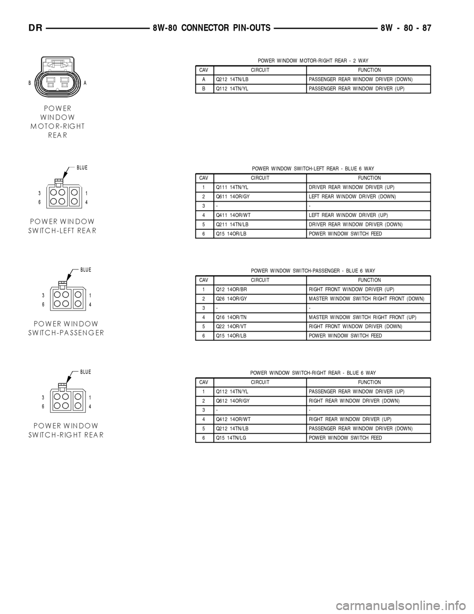
POWER WINDOW MOTOR-RIGHT REAR-2WAY
CAV CIRCUIT FUNCTION
A Q212 14TN/LB PASSENGER REAR WINDOW DRIVER (DOWN)
B Q112 14TN/YL PASSENGER REAR WINDOW DRIVER (UP)
POWER WINDOW SWITCH-LEFT REAR - BLUE 6 WAY
CAV CIRCUIT FUNCTION
1 Q111 14TN/YL DRIVER REAR WINDOW DRIVER (UP)
2 Q611 14OR/GY LEFT REAR WINDOW DRIVER (DOWN)
3- -
4 Q411 14OR/WT LEFT REAR WINDOW DRIVER (UP)
5 Q211 14TN/LB DRIVER REAR WINDOW DRIVER (DOWN)
6 Q15 14OR/LB POWER WINDOW SWITCH FEED
POWER WINDOW SWITCH-PASSENGER - BLUE 6 WAY
CAV CIRCUIT FUNCTION
1 Q12 14OR/BR RIGHT FRONT WINDOW DRIVER (UP)
2 Q26 14OR/GY MASTER WINDOW SWITCH RIGHT FRONT (DOWN)
3- -
4 Q16 14OR/TN MASTER WINDOW SWITCH RIGHT FRONT (UP)
5 Q22 14OR/VT RIGHT FRONT WINDOW DRIVER (DOWN)
6 Q15 14OR/LB POWER WINDOW SWITCH FEED
POWER WINDOW SWITCH-RIGHT REAR - BLUE 6 WAY
CAV CIRCUIT FUNCTION
1 Q112 14TN/YL PASSENGER REAR WINDOW DRIVER (UP)
2 Q612 14OR/GY RIGHT REAR WINDOW DRIVER (DOWN)
3- -
4 Q412 14OR/WT RIGHT REAR WINDOW DRIVER (UP)
5 Q212 14TN/LB PASSENGER REAR WINDOW DRIVER (DOWN)
6 Q15 14TN/LG POWER WINDOW SWITCH FEED
DR8W-80 CONNECTOR PIN-OUTS 8W - 80 - 87
Page 1159 of 2627
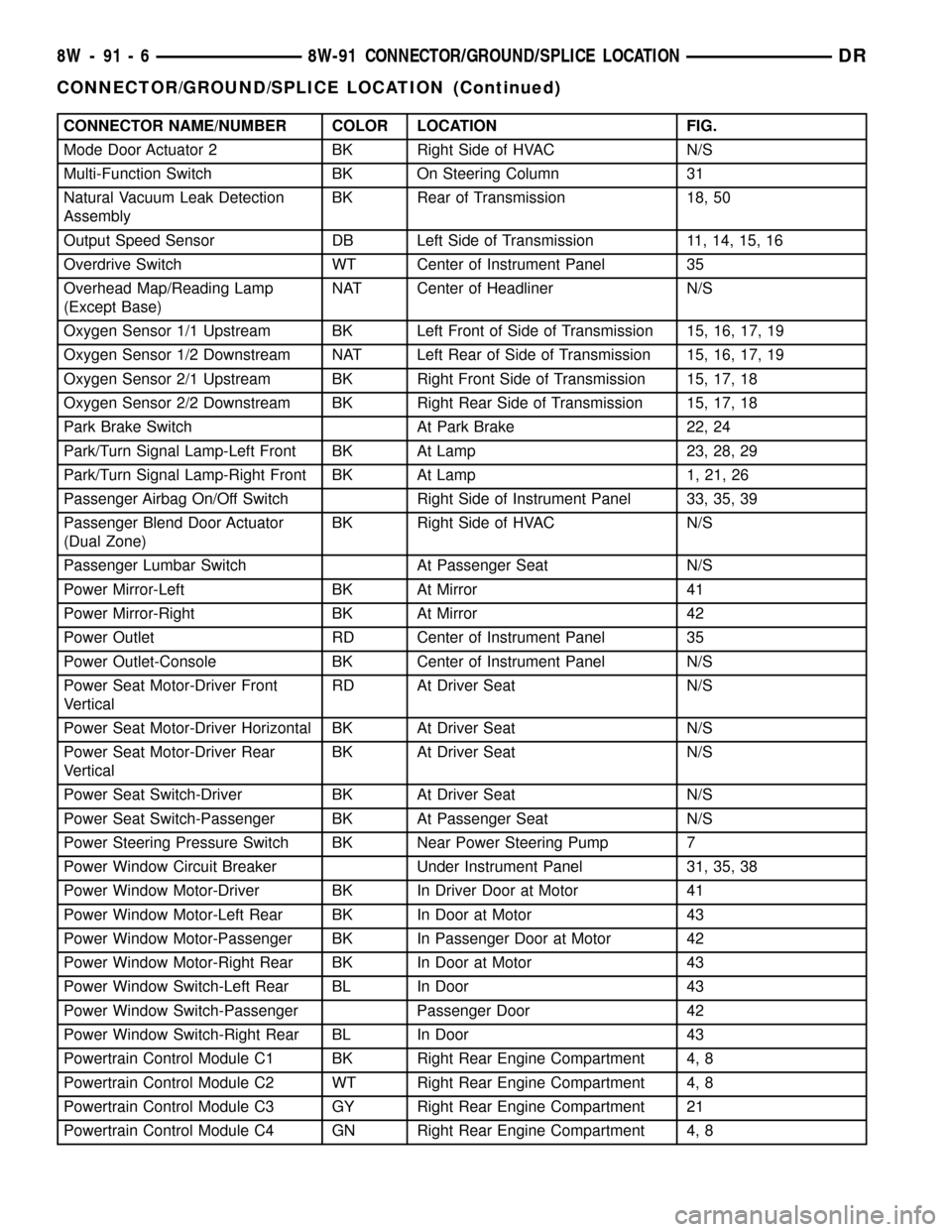
CONNECTOR NAME/NUMBER COLOR LOCATION FIG.
Mode Door Actuator 2 BK Right Side of HVAC N/S
Multi-Function Switch BK On Steering Column 31
Natural Vacuum Leak Detection
AssemblyBK Rear of Transmission 18, 50
Output Speed Sensor DB Left Side of Transmission 11, 14, 15, 16
Overdrive Switch WT Center of Instrument Panel 35
Overhead Map/Reading Lamp
(Except Base)NAT Center of Headliner N/S
Oxygen Sensor 1/1 Upstream BK Left Front of Side of Transmission 15, 16, 17, 19
Oxygen Sensor 1/2 Downstream NAT Left Rear of Side of Transmission 15, 16, 17, 19
Oxygen Sensor 2/1 Upstream BK Right Front Side of Transmission 15, 17, 18
Oxygen Sensor 2/2 Downstream BK Right Rear Side of Transmission 15, 17, 18
Park Brake Switch At Park Brake 22, 24
Park/Turn Signal Lamp-Left Front BK At Lamp 23, 28, 29
Park/Turn Signal Lamp-Right Front BK At Lamp 1, 21, 26
Passenger Airbag On/Off Switch Right Side of Instrument Panel 33, 35, 39
Passenger Blend Door Actuator
(Dual Zone)BK Right Side of HVAC N/S
Passenger Lumbar Switch At Passenger Seat N/S
Power Mirror-Left BK At Mirror 41
Power Mirror-Right BK At Mirror 42
Power Outlet RD Center of Instrument Panel 35
Power Outlet-Console BK Center of Instrument Panel N/S
Power Seat Motor-Driver Front
VerticalRD At Driver Seat N/S
Power Seat Motor-Driver Horizontal BK At Driver Seat N/S
Power Seat Motor-Driver Rear
VerticalBK At Driver Seat N/S
Power Seat Switch-Driver BK At Driver Seat N/S
Power Seat Switch-Passenger BK At Passenger Seat N/S
Power Steering Pressure Switch BK Near Power Steering Pump 7
Power Window Circuit Breaker Under Instrument Panel 31, 35, 38
Power Window Motor-Driver BK In Driver Door at Motor 41
Power Window Motor-Left Rear BK In Door at Motor 43
Power Window Motor-Passenger BK In Passenger Door at Motor 42
Power Window Motor-Right Rear BK In Door at Motor 43
Power Window Switch-Left Rear BL In Door 43
Power Window Switch-Passenger Passenger Door 42
Power Window Switch-Right Rear BL In Door 43
Powertrain Control Module C1 BK Right Rear Engine Compartment 4, 8
Powertrain Control Module C2 WT Right Rear Engine Compartment 4, 8
Powertrain Control Module C3 GY Right Rear Engine Compartment 21
Powertrain Control Module C4 GN Right Rear Engine Compartment 4, 8
8W - 91 - 6 8W-91 CONNECTOR/GROUND/SPLICE LOCATIONDR
CONNECTOR/GROUND/SPLICE LOCATION (Continued)
Page 2290 of 2627
WHEELS
DESCRIPTION
Original equipment wheels are designed for the
specified Maximum Vehicle Capacity.
All models use steel or aluminum drop center
wheels.
Aluminum wheels require special balance weights
and alignment equipment.
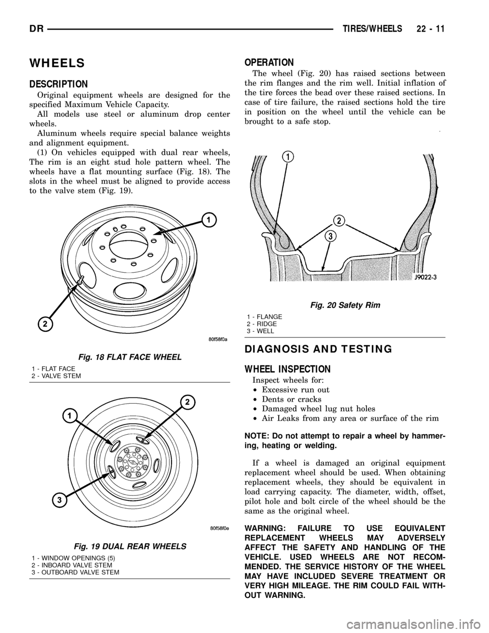
(1) On vehicles equipped with dual rear wheels,
The rim is an eight stud hole pattern wheel. The
wheels have a flat mounting surface (Fig. 18). The
slots in the wheel must be aligned to provide access
to the valve stem (Fig. 19).
OPERATION
The wheel (Fig. 20) has raised sections between
the rim flanges and the rim well. Initial inflation of
the tire forces the bead over these raised sections. In
case of tire failure, the raised sections hold the tire
in position on the wheel until the vehicle can be
brought to a safe stop.
DIAGNOSIS AND TESTING
WHEEL INSPECTION
Inspect wheels for:
²Excessive run out
²Dents or cracks
²Damaged wheel lug nut holes
²Air Leaks from any area or surface of the rim
NOTE: Do not attempt to repair a wheel by hammer-
ing, heating or welding.
If a wheel is damaged an original equipment
replacement wheel should be used. When obtaining
replacement wheels, they should be equivalent in
load carrying capacity. The diameter, width, offset,
pilot hole and bolt circle of the wheel should be the
same as the original wheel.
WARNING: FAILURE TO USE EQUIVALENT
REPLACEMENT WHEELS MAY ADVERSELY
AFFECT THE SAFETY AND HANDLING OF THE
VEHICLE. USED WHEELS ARE NOT RECOM-
MENDED. THE SERVICE HISTORY OF THE WHEEL
MAY HAVE INCLUDED SEVERE TREATMENT OR
VERY HIGH MILEAGE. THE RIM COULD FAIL WITH-
OUT WARNING.
Fig. 18 FLAT FACE WHEEL
1 - FLAT FACE
2 - VALVE STEM
Fig. 19 DUAL REAR WHEELS
1 - WINDOW OPENINGS (5)
2 - INBOARD VALVE STEM
3 - OUTBOARD VALVE STEM
Fig. 20 Safety Rim
1 - FLANGE
2 - RIDGE
3 - WELL
DRTIRES/WHEELS 22 - 11
Page 2293 of 2627

STUDS
REMOVAL
(1) Raise and support the vehicle.
(2) Remove the wheel and tire assembly.
(3) Remove the brake caliper, caliper adapter and
rotor, (Refer to 5 - BRAKES/HYDRAULIC/MECHAN-
ICAL/ROTORS - REMOVAL).
(4) Remove the stud from the hub with Remover
C-4150A (Fig. 25).
INSTALLATION
(1) Install the new stud into the hub flange.
(2) Install the three washers onto the stud, then
install the lug nut with the flat side of the nut
against the washers.
(3) Tighten the lug nut until the stud is pulled
into the hub flange. Verify that the stud is properly
seated into the flange.
(4) Remove the lug nut and washers.
(5) Install the brake rotor, caliper adapter, and cal-
iper, (Refer to 5 - BRAKES/HYDRAULIC/MECHAN-
ICAL/ROTORS - INSTALLATION).
(6) Install the wheel and tire assembly, (Refer to
22 - TIRES/WHEELS/WHEELS - STANDARD PRO-
CEDURE), use new the lug nut on stud or studs that
were replaced.
(7) Remove the support and lower vehicle.
WHEEL COVER
REMOVAL
NOTE: The hub caps must be removed before rais-
ing the vehicle off the ground.NOTE: You must use the flat end of the hub/cap
remover/installer combination tool to pry off the
wheel skins. Insert the flat tip completely and using
a back and forth motion, loosen the wheel skin.
repeat this procedure around the tire until the wheel
skin pops off.
(1) On 2500/3500 single rear wheel (SRW) models,
insert a hub/cap remover/installer combination tool
using the blade on the end of the tool to pry the cap
off in a back and forth motion.
(2) On 3500 models with dual rear wheels (DRW),
you must first remove the hub caps. The hub/cap
remover/installer combination tool must be inserted
in the pry off notch of the rear hub caps.
(3) Position the hub/cap remover/installer combina-
tion tool and pull out on the tool firmly. The cap
should come off.
(4) The wheel skins can now be removed from the
wheel.
(5) On 3500 models front hub caps use the hub/cap
remover/installer combination tool to pry off the cap
in a back and forth motion. The wheel skins can now
be removed.
INSTALLATION
INSTALLATION - REAR
(1) Install one 1 1/2 in. valve stem extension on
each rear inner wheel.
NOTE: A 3/8 in. drive 10mm deep wheel socket with
a 10 in. or greater extension can be used to remove
the existing valve stem cap and install the exten-
sion.
(2) Install one 1 in. valve stem extension on each
outer wheel.
(3) Align the cooling windows of the wheel skin
with the cooling windows of the wheel. Seat one side
of the wheel skin's retainer onto the wheel. Using a
rubber mallet, strike thew wheel skin on the outer
circumference. Strike at several locations around the
circumference until the skin is fully seated.
NOTE: The wheel skin and the hub cap are fully
seated when there is a consistent gap between the
skin/cap and the wheel.
(4) Tug on the hub/cap wheel skin to ensure that
they are properly installed.
INSTALLATION - FRONT
(1) Align the valve stem with the notch in the
wheel skin.
Fig. 25 Wheel Stud Removal
1 - REMOVER
2 - WHEEL STUD
22 - 14 TIRES/WHEELSDR
Page 2297 of 2627

VISUAL INSPECTION BEFORE WATER LEAK TESTS
Verify that floor and body plugs are in place, body
drains are clear, and body components are properly
aligned and sealed. If component alignment or seal-
ing is necessary, refer to the appropriate section of
this group for proper procedures.
WATER LEAK TESTS
WARNING: DO NOT USE ELECTRIC SHOP LIGHTS
OR TOOLS IN WATER TEST AREA. PERSONAL
INJURY CAN RESULT.
When the conditions causing a water leak have
been determined, simulate the conditions as closely
as possible.
²If a leak occurs with the vehicle parked in a
steady light rain, flood the leak area with an open-
ended garden hose.
²If a leak occurs while driving at highway speeds
in a steady rain, test the leak area with a reasonable
velocity stream or fan spray of water. Direct the
spray in a direction comparable to actual conditions.
²If a leak occurs when the vehicle is parked on an
incline, hoist the end or side of the vehicle to simu-
late this condition. This method can be used when
the leak occurs when the vehicle accelerates, stops or
turns. If the leak occurs on acceleration, hoist the
front of the vehicle. If the leak occurs when braking,
hoist the back of the vehicle. If the leak occurs on left
turns, hoist the left side of the vehicle. If the leak
occurs on right turns, hoist the right side of the vehi-
cle. For hoisting recommendations (Refer to LUBRI-
CATION & MAINTENANCE/HOISTING -
STANDARD PROCEDURE).
WATER LEAK DETECTION
To detect a water leak point-of-entry, do a water
test and watch for water tracks or droplets forming
on the inside of the vehicle. If necessary, remove inte-
rior trim covers or panels to gain visual access to the
leak area. If the hose cannot be positioned without
being held, have someone help do the water test.
Some water leaks must be tested for a considerable
length of time to become apparent. When a leak
appears, find the highest point of the water track or
drop. The highest point usually will show the point of
entry. After leak point has been found, repair the
leak and water test to verify that the leak has
stopped.
Locating the entry point of water that is leaking
into a cavity between panels can be difficult. The
trapped water may splash or run from the cavity,
often at a distance from the entry point. Most water
leaks of this type become apparent after accelerating,
stopping, turning, or when on an incline.MIRROR INSPECTION METHOD
When a leak point area is visually obstructed, use
a suitable mirror to gain visual access. A mirror can
also be used to deflect light to a limited-access area
to assist in locating a leak point.
BRIGHT LIGHT LEAK TEST METHOD
Some water leaks in the luggage compartment can
be detected without water testing. Position the vehi-
cle in a brightly lit area. From inside the darkened
luggage compartment inspect around seals and body
seams. If necessary, have a helper direct a drop light
over the suspected leak areas around the luggage
compartment. If light is visible through a normally
sealed location, water could enter through the open-
ing.
PRESSURIZED LEAK TEST METHOD
When a water leak into the passenger compart-
ment cannot be detected by water testing, pressurize
the passenger compartment and soap test exterior of
the vehicle. To pressurize the passenger compart-
ment, close all doors and windows, start engine, and
set heater control to high blower in HEAT position. If
engine can not be started, connect a charger to the
battery to ensure adequate voltage to the blower.
With interior pressurized, apply dish detergent solu-
tion to suspected leak area on the exterior of the
vehicle. Apply detergent solution with spray device or
soft bristle brush. If soap bubbles occur at a body
seam, joint, seal or gasket, the leak entry point could
be at that location.
DIAGNOSIS AND TESTING - WIND NOISE
Wind noise is the result of most air leaks. Air leaks
can be caused by poor sealing, improper body compo-
nent alignment, body seam porosity, or missing plugs
in the engine compartment or door hinge pillar areas.
All body sealing points should be airtight in normal
driving conditions. Moving sealing surfaces will not
always seal airtight under all conditions. At times,
side glass or door seals will allow wind noise to be
noticed in the passenger compartment during high
cross winds. Over compensating on door or glass
adjustments to stop wind noise that occurs under
severe conditions can cause premature seal wear and
excessive closing or latching effort. After a repair pro-
cedure has been performed, test vehicle to verify
noise has stopped before returning vehicle to use.
VISUAL INSPECTION BEFORE TESTS
Verify that floor and body plugs are in place and
body components are aligned and sealed. If compo-
nent alignment or sealing is necessary, refer to the
appropriate section of this group for proper proce-
dures.
23 - 2 BODYDR
BODY (Continued)
Page 2300 of 2627
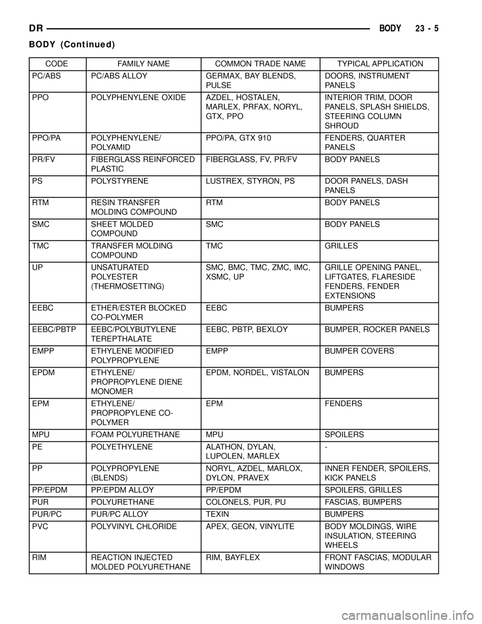
CODE FAMILY NAME COMMON TRADE NAME TYPICAL APPLICATION
PC/ABS PC/ABS ALLOY GERMAX, BAY BLENDS,
PULSEDOORS, INSTRUMENT
PANELS
PPO POLYPHENYLENE OXIDE AZDEL, HOSTALEN,
MARLEX, PRFAX, NORYL,
GTX, PPOINTERIOR TRIM, DOOR
PANELS, SPLASH SHIELDS,
STEERING COLUMN
SHROUD
PPO/PA POLYPHENYLENE/
POLYAMIDPPO/PA, GTX 910 FENDERS, QUARTER
PANELS
PR/FV FIBERGLASS REINFORCED
PLASTICFIBERGLASS, FV, PR/FV BODY PANELS
PS POLYSTYRENE LUSTREX, STYRON, PS DOOR PANELS, DASH
PANELS
RTM RESIN TRANSFER
MOLDING COMPOUNDRTM BODY PANELS
SMC SHEET MOLDED
COMPOUNDSMC BODY PANELS
TMC TRANSFER MOLDING
COMPOUNDTMC GRILLES
UP UNSATURATED
POLYESTER
(THERMOSETTING)SMC, BMC, TMC, ZMC, IMC,
XSMC, UPGRILLE OPENING PANEL,
LIFTGATES, FLARESIDE
FENDERS, FENDER
EXTENSIONS
EEBC ETHER/ESTER BLOCKED
CO-POLYMEREEBC BUMPERS
EEBC/PBTP EEBC/POLYBUTYLENE
TEREPTHALATEEEBC, PBTP, BEXLOY BUMPER, ROCKER PANELS
EMPP ETHYLENE MODIFIED
POLYPROPYLENEEMPP BUMPER COVERS
EPDM ETHYLENE/
PROPROPYLENE DIENE
MONOMEREPDM, NORDEL, VISTALON BUMPERS
EPM ETHYLENE/
PROPROPYLENE CO-
POLYMEREPM FENDERS
MPU FOAM POLYURETHANE MPU SPOILERS
PE POLYETHYLENE ALATHON, DYLAN,
LUPOLEN, MARLEX-
PP POLYPROPYLENE
(BLENDS)NORYL, AZDEL, MARLOX,
DYLON, PRAVEXINNER FENDER, SPOILERS,
KICK PANELS
PP/EPDM PP/EPDM ALLOY PP/EPDM SPOILERS, GRILLES
PUR POLYURETHANE COLONELS, PUR, PU FASCIAS, BUMPERS
PUR/PC PUR/PC ALLOY TEXIN BUMPERS
PVC POLYVINYL CHLORIDE APEX, GEON, VINYLITE BODY MOLDINGS, WIRE
INSULATION, STEERING
WHEELS
RIM REACTION INJECTED
MOLDED POLYURETHANERIM, BAYFLEX FRONT FASCIAS, MODULAR
WINDOWS
DRBODY 23 - 5
BODY (Continued)
Page 2313 of 2627

DOOR - FRONT
TABLE OF CONTENTS
page page
DOOR
REMOVAL.............................18
INSTALLATION.........................18
ADJUSTMENTS
ADJUSTMENT........................19
DOOR GLASS
REMOVAL.............................20
INSTALLATION.........................20
EXTERIOR HANDLE
REMOVAL.............................20
INSTALLATION.........................21
GLASS RUN CHANNEL
REMOVAL.............................21
INSTALLATION.........................22
HINGE
REMOVAL.............................22
INSTALLATION.........................22
INSIDE HANDLE ACTUATOR
REMOVAL.............................22
INSTALLATION.........................22
LATCH
REMOVAL.............................23
INSTALLATION.........................23
ADJUSTMENTS
ADJUSTMENT........................23LATCH STRIKER
REMOVAL.............................23
INSTALLATION.........................23
ADJUSTMENTS
ADJUSTMENT........................24
LOCK CYLINDER
REMOVAL.............................24
INSTALLATION.........................24
TRIM PANEL
REMOVAL.............................24
INSTALLATION.........................24
WATERDAM
REMOVAL.............................25
INSTALLATION.........................25
WINDOW REGULATOR - POWER
REMOVAL.............................25
INSTALLATION.........................26
WINDOW REGULATOR - MANUAL
REMOVAL.............................26
INSTALLATION.........................27
SIDE VIEW MIRROR FLAG
REMOVAL.............................27
INSTALLATION.........................27
DOOR
REMOVAL
(1) Disconnect the door wire harness electrical con-
nector at the A-pillar. (Fig. 1)
(2) Using a grease pencil or equivalent, mark the
outline of the door hinges on the door to aid in instal-
lation.
(3) Support the door with a suitable lifting device.
NOTE: The epoxy bonded washers should not be
seperated from the hinge. If the washers are
removed the door may have to be re-adjusted.
(4) Remove the nuts and bolts attaching the door
hinges to the door.
INSTALLATION
(1) Support the door with a suitable lifting device
and install the door onto the hinges.
(2) Install the washers, if there were removed pre-
viously, nuts and tighten to 28 N´m (21 ft. lbs.).
(3) Connect the electrical connectors.
(4) Adjust the door as necessary. (Refer to 23 -
BODY/DOOR - FRONT/DOOR - ADJUSTMENTS)
23 - 18 DOOR - FRONTDR
Page 2315 of 2627

(4) Adjust the door to the correct position. (Refer
to 23 - BODY/BODY STRUCTURE/GAP AND
FLUSH - SPECIFICATIONS)
(5) Tighten the door to hinges fasteners to 28 N´m
(21 ft. lbs.).
(6) Tighten the latch striker bolts. (Refer to 23 -
BODY/DOOR - FRONT/LATCH STRIKER - INSTAL-
LATION)
DOOR GLASS
REMOVAL
(1) Remove the waterdam. (Refer to 23 - BODY/
DOOR - FRONT/WATERDAM - REMOVAL)
(2) Reinstall the window handle, if equipped.
(3) Remove the window switch from the door trim
panel and reconnect it to the door wire harness, if
equipped.
(4) Raise the window to the position shown and
remove the two nuts attaching the glass to the win-
dow regulator. (Fig. 2)
(5) Remove the two front run channel screws.
(Refer to 23 - BODY/DOOR - FRONT/GLASS RUN
CHANNEL - REMOVAL)
(6) Remove the inner belt molding. (Refer to 23 -
BODY/WEATHERSTRIP/SEALS/FRONT DOOR
INNER BELT WEATHERSTRIP - REMOVAL)
(7) Disengage the glass from the regulator and
lower into the door.
(8) Twist the glass forward in the door window
opening and remove.
INSTALLATION
(1) Position the glass into the window opening.(2) Engage the glass into the glass run weather-
strip.
(3) Raise the glass within the door opening and
connect the window regulator to the lift plate.
(4) Install the nuts and tighten to 10 N´m (89 in.
lbs.).
(5) Install the inner belt molding. (Refer to 23 -
BODY/WEATHERSTRIP/SEALS/FRONT DOOR
INNER BELT WEATHERSTRIP - INSTALLATION)
(6) Position the front run channel and install the
screws. (Refer to 23 - BODY/DOOR - FRONT/GLASS
RUN CHANNEL - INSTALLATION)
(7) Remove the window switch from the wire har-
ness, if equipped.
(8) Remove the window handle, if equipped.
(9) Install the waterdam. (Refer to 23 - BODY/
DOOR - FRONT/WATERDAM - INSTALLATION)
EXTERIOR HANDLE
REMOVAL
(1) Remove the door glass. (Refer to 23 - BODY/
DOOR - FRONT/DOOR GLASS - REMOVAL)
(2) Disconnect the lock switch electrical connector,
if equipped. (Fig. 3)
(3) Disconnect the actuator rods at the handle.
(4) Remove the nuts and remove the handle.
Fig. 2 DOOR GLASS POSITIONING
1 - SIGHT WINDOW
2 - WIDOW REGULATOR
3 - SIGHT WINDOW
4 - REGULATOR STABILIZER
Fig. 3 EXTERIOR HANDLE
1 - EXTERIOR HANDLE
2 - NUTS (2)
3 - ELECTRICAL CONNECTOR
4 - FRONT DOOR
5 - DOOR LATCH ASSEMBLY
6 - LATCH ACTUATOR ROD
7 - LOCK SWITCH WIRE HARNESS
8 - KEY CYLINDER ACTUATOR ROD
23 - 20 DOOR - FRONTDR
DOOR (Continued)
Page 2316 of 2627

INSTALLATION
(1) Install the exterior handle and install the nuts.
(2) Connect the actuator rods at the handle
(3) Connect the lock switch electrical connector, if
equipped.
(4) Install the door glass. (Refer to 23 - BODY/
DOOR - FRONT/DOOR GLASS - INSTALLATION)
GLASS RUN CHANNEL
REMOVAL
(1) Raise glass into the full up position.
(2) Remove the waterdam. (Refer to 23 - BODY/
DOOR - FRONT/WATERDAM - REMOVAL)
FRONT RUN CHANNEL
(1) Remove the window regulator. (Refer to 23 -
BODY/DOOR - FRONT/WINDOW REGULATOR -
REMOVAL)
(2) Loosen the front run channel screws, slide up
and disengage from the door. (Fig. 4)
(3) Separate the glass run weatherstrip from the
channel and remove the front channel.
REAR RUN CHANNEL
(1) On standard cab models, remove the screws
from the side of the door. (Fig. 5)
(2) On quad cab models, remove the lower screw
from the side of the door, loosen the upper screw and
disengage from the door. (Fig. 6)(3) Separate the glass run weatherstrip from the
rear channel and remove the channel.
Fig. 4 FRONT RUN CHANNEL
1 - FRONT GLASS RUN CHANNEL
2 - UPPER SCREW
3 - LOWER SCREW
4 - DOOR PANEL OPENING
5 - RUN CHANNEL MOUNTING SLOTS (2)
Fig. 5 REAR RUN CHANNEL - QUAD CAB
1 - SCREWS
2 - REAR GLASS RUN CHANNEL
3 - DOOR PANEL OPENING
Fig. 6 REAR RUN CHANNEL - STANDARD CAB
1 - LOWER SCREW
2 - DOOR PANEL OPENING
3 - REAR GLASS RUN CHANNEL
4 - UPPER SCREW
DRDOOR - FRONT 23 - 21
EXTERIOR HANDLE (Continued)