Fuel filter DODGE RAM 1500 1998 2.G Repair Manual
[x] Cancel search | Manufacturer: DODGE, Model Year: 1998, Model line: RAM 1500, Model: DODGE RAM 1500 1998 2.GPages: 2627
Page 1626 of 2627

FUEL LEVEL SENDING UNIT /
SENSOR
DESCRIPTION
The fuel gauge sending unit (fuel level sensor) is
attached to the side of the fuel tank module. The
sending unit consists of a float, an arm, and a vari-
able resistor track (card).
OPERATION
The fuel tank module on diesel powered models
has 2 different circuits (wires). Two of these circuits
are used at the fuel gauge sending unit for fuel
gauge operation. The diesel engine does not have a
fuel tank module mounted electric fuel pump. The
electric fuel pump (fuel transfer pump) is mounted to
the engine.
For Fuel Gauge Operation:A constant input
voltage source of about 12 volts (battery voltage) is
supplied to the resistor track on the fuel gauge send-
ing unit. This is fed directly from the Engine Control
Module (ECM).NOTE: For diagnostic purposes,
this 12V power source can only be verified with
the circuit opened (fuel tank module electrical
connector unplugged). With the connectors
plugged, output voltages will vary from about .6
volts at FULL, to about 7.0 volts at EMPTY.The
resistor track is used to vary the voltage (resistance)
depending on fuel tank float level. As fuel level
increases, the float and arm move up, which
decreases voltage. As fuel level decreases, the float
and arm move down, which increases voltage. The
varied voltage signal is returned back to the ECM
through the sensor return circuit.
Both of the electrical circuits between the fuel
gauge sending unit and the ECM are hard-wired (not
multi-plexed). After the voltage signal is sent from
the resistor track, and back to the ECM, the ECM
will interpret the resistance (voltage) data and send
a message across the multi-plex bus circuits to the
instrument panel cluster. Here it is translated into
the appropriate fuel gauge level reading. Refer to
Instrument Panel for additional information.
REMOVAL
REMOVAL/INSTALLATION
For diesel removal and installation procedures,
refer to the gas section of Fuel System/Fuel Delivery.
See Fuel Level Sending Unit/Sensor Removal/Instal-
lation.
FUEL LINES
DESCRIPTION
Low-Pressure Lines Are:
²the fuel supply line from fuel tank to fuel trans-
fer (lift) pump.
²the fuel return line back to fuel tank.
²the fuel drain (manifold) line at rear of cylinder
head.
²the fuel supply line from fuel filter to fuel injec-
tion pump.
²the fuel injection pump return line.
High-Pressure Lines Are:
²the fuel line from fuel injection pump to fuel
rail.
²the 6 fuel lines from fuel rail up to injector con-
nector tubes
WARNING: HIGH-PRESSURE FUEL LINES DELIVER
DIESEL FUEL UNDER EXTREME PRESSURE FROM
THE INJECTION PUMP TO THE FUEL INJECTORS.
THIS MAY BE AS HIGH AS 160,000 KPA (23,206
PSI). USE EXTREME CAUTION WHEN INSPECTING
FOR HIGH-PRESSURE FUEL LEAKS. INSPECT FOR
HIGH-PRESSURE FUEL LEAKS WITH A SHEET OF
CARDBOARD. HIGH FUEL INJECTION PRESSURE
CAN CAUSE PERSONAL INJURY IF CONTACT IS
MADE WITH THE SKIN.
OPERATION
High-Pressure Lines
CAUTION: The high-pressure fuel lines must be
held securely in place in their holders. The lines
cannot contact each other or other components. Do
not attempt to weld high-pressure fuel lines or to
repair lines that are damaged. If lines are ever
kinked or bent, they must be replaced. Use only the
recommended lines when replacement of high-pres-
sure fuel line is necessary.
High-pressure fuel lines deliver fuel (under pres-
sure) of up to approximately 160,000 kPa (23,206
PSI) from the injection pump to the fuel injectors.
The lines expand and contract from the high-pres-
sure fuel pulses generated during the injection pro-
cess. All high-pressure fuel lines are of the same
length and inside diameter. Correct high-pressure
fuel line usage and installation is critical to smooth
engine operation.
DRFUEL DELIVERY - DIESEL 14 - 57
Page 1632 of 2627
FUEL TANK MODULE
DESCRIPTION
An electric fuel pump isnot usedin the fuel tank
module for diesel powered engines. Fuel is supplied
by the engine mounted fuel transfer (lift) pump.
The fuel tank module is installed in the top of the
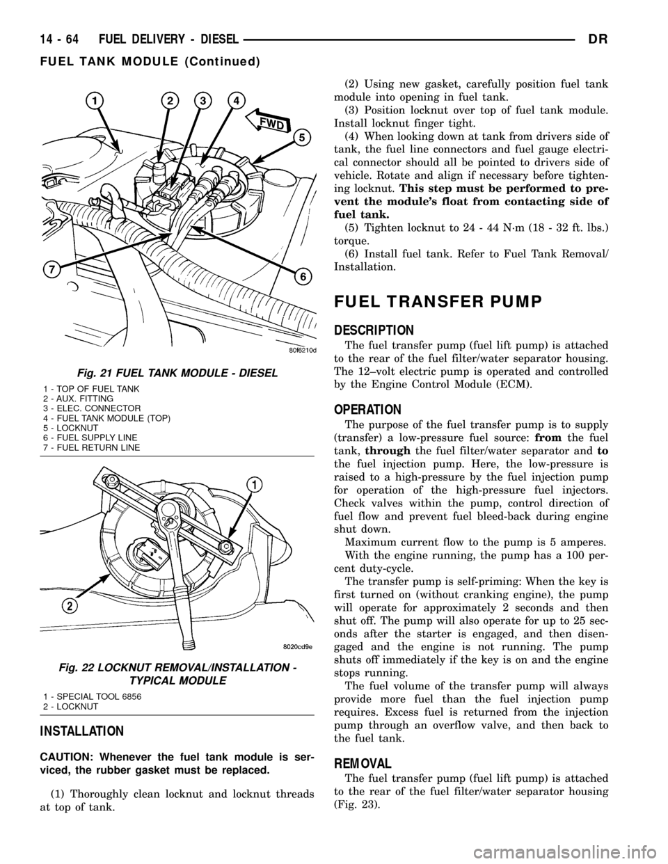
fuel tank (Fig. 21). The fuel tank module contains
the following components:
²Fuel reservoir
²A separate in-tank fuel filter
²Fuel gauge sending unit (fuel level sensor)
²Fuel supply line connection
²Fuel return line connection
²Auxiliary non-pressurized fitting
OPERATION
Refer to Fuel Gauge Sending Unit.
REMOVAL
(1) Drain and remove fuel tank. Refer to Fuel
Tank Removal/Installation.
(2) Thoroughly clean area around tank module at
top of tank.
(3) The plastic fuel tank module locknut is
threaded onto fuel tank. Install Special Tool 6856 to
locknut and remove locknut (Fig. 22). The fuel tank
module will spring up when locknut is removed.
(4) Remove module from fuel tank.
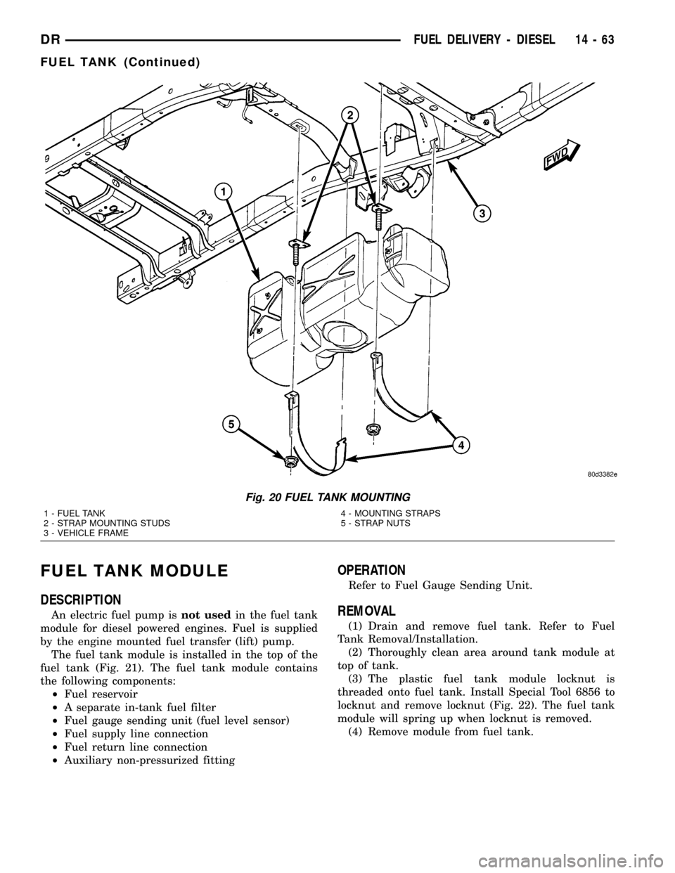
Fig. 20 FUEL TANK MOUNTING
1 - FUEL TANK
2 - STRAP MOUNTING STUDS
3 - VEHICLE FRAME4 - MOUNTING STRAPS
5 - STRAP NUTS
DRFUEL DELIVERY - DIESEL 14 - 63
FUEL TANK (Continued)
Page 1633 of 2627
INSTALLATION
CAUTION: Whenever the fuel tank module is ser-
viced, the rubber gasket must be replaced.
(1) Thoroughly clean locknut and locknut threads
at top of tank.(2) Using new gasket, carefully position fuel tank
module into opening in fuel tank.
(3) Position locknut over top of fuel tank module.
Install locknut finger tight.
(4) When looking down at tank from drivers side of
tank, the fuel line connectors and fuel gauge electri-
cal connector should all be pointed to drivers side of
vehicle. Rotate and align if necessary before tighten-
ing locknut.This step must be performed to pre-
vent the module's float from contacting side of
fuel tank.
(5) Tighten locknut to 24 - 44 N´m (18 - 32 ft. lbs.)
torque.
(6) Install fuel tank. Refer to Fuel Tank Removal/
Installation.
FUEL TRANSFER PUMP
DESCRIPTION
The fuel transfer pump (fuel lift pump) is attached
to the rear of the fuel filter/water separator housing.
The 12±volt electric pump is operated and controlled
by the Engine Control Module (ECM).
OPERATION
The purpose of the fuel transfer pump is to supply
(transfer) a low-pressure fuel source:fromthe fuel
tank,throughthe fuel filter/water separator andto
the fuel injection pump. Here, the low-pressure is
raised to a high-pressure by the fuel injection pump
for operation of the high-pressure fuel injectors.
Check valves within the pump, control direction of
fuel flow and prevent fuel bleed-back during engine
shut down.
Maximum current flow to the pump is 5 amperes.
With the engine running, the pump has a 100 per-
cent duty-cycle.
The transfer pump is self-priming: When the key is
first turned on (without cranking engine), the pump
will operate for approximately 2 seconds and then
shut off. The pump will also operate for up to 25 sec-
onds after the starter is engaged, and then disen-
gaged and the engine is not running. The pump
shuts off immediately if the key is on and the engine
stops running.
The fuel volume of the transfer pump will always
provide more fuel than the fuel injection pump
requires. Excess fuel is returned from the injection
pump through an overflow valve, and then back to
the fuel tank.
REMOVAL
The fuel transfer pump (fuel lift pump) is attached
to the rear of the fuel filter/water separator housing
(Fig. 23).
Fig. 21 FUEL TANK MODULE - DIESEL
1 - TOP OF FUEL TANK
2 - AUX. FITTING
3 - ELEC. CONNECTOR
4 - FUEL TANK MODULE (TOP)
5 - LOCKNUT
6 - FUEL SUPPLY LINE
7 - FUEL RETURN LINE
Fig. 22 LOCKNUT REMOVAL/INSTALLATION -
TYPICAL MODULE
1 - SPECIAL TOOL 6856
2 - LOCKNUT
14 - 64 FUEL DELIVERY - DIESELDR
FUEL TANK MODULE (Continued)
Page 1634 of 2627
(1) Drain fuel from fuel filter housing. Refer to
Fuel Filter/Water Separator - Removal. See Draining.
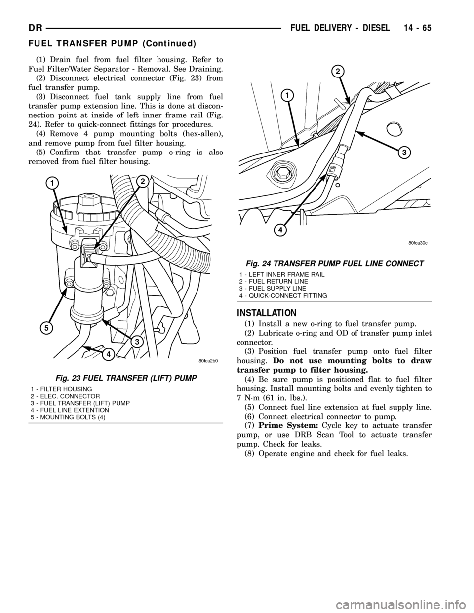
(2) Disconnect electrical connector (Fig. 23) from
fuel transfer pump.
(3) Disconnect fuel tank supply line from fuel
transfer pump extension line. This is done at discon-
nection point at inside of left inner frame rail (Fig.
24). Refer to quick-connect fittings for procedures.
(4) Remove 4 pump mounting bolts (hex-allen),
and remove pump from fuel filter housing.
(5) Confirm that transfer pump o-ring is also
removed from fuel filter housing.
INSTALLATION
(1) Install a new o-ring to fuel transfer pump.
(2) Lubricate o-ring and OD of transfer pump inlet
connector.
(3) Position fuel transfer pump onto fuel filter
housing.Do not use mounting bolts to draw
transfer pump to filter housing.
(4) Be sure pump is positioned flat to fuel filter
housing. Install mounting bolts and evenly tighten to
7 N´m (61 in. lbs.).
(5) Connect fuel line extension at fuel supply line.
(6) Connect electrical connector to pump.
(7)Prime System:Cycle key to actuate transfer
pump, or use DRB Scan Tool to actuate transfer
pump. Check for leaks.
(8) Operate engine and check for fuel leaks.
Fig. 23 FUEL TRANSFER (LIFT) PUMP
1 - FILTER HOUSING
2 - ELEC. CONNECTOR
3 - FUEL TRANSFER (LIFT) PUMP
4 - FUEL LINE EXTENTION
5 - MOUNTING BOLTS (4)
Fig. 24 TRANSFER PUMP FUEL LINE CONNECT
1 - LEFT INNER FRAME RAIL
2 - FUEL RETURN LINE
3 - FUEL SUPPLY LINE
4 - QUICK-CONNECT FITTING
DRFUEL DELIVERY - DIESEL 14 - 65
FUEL TRANSFER PUMP (Continued)
Page 1635 of 2627
CASCADE OVERFLOW VALVE
DESCRIPTION
The cascade overflow valve is located on the top/
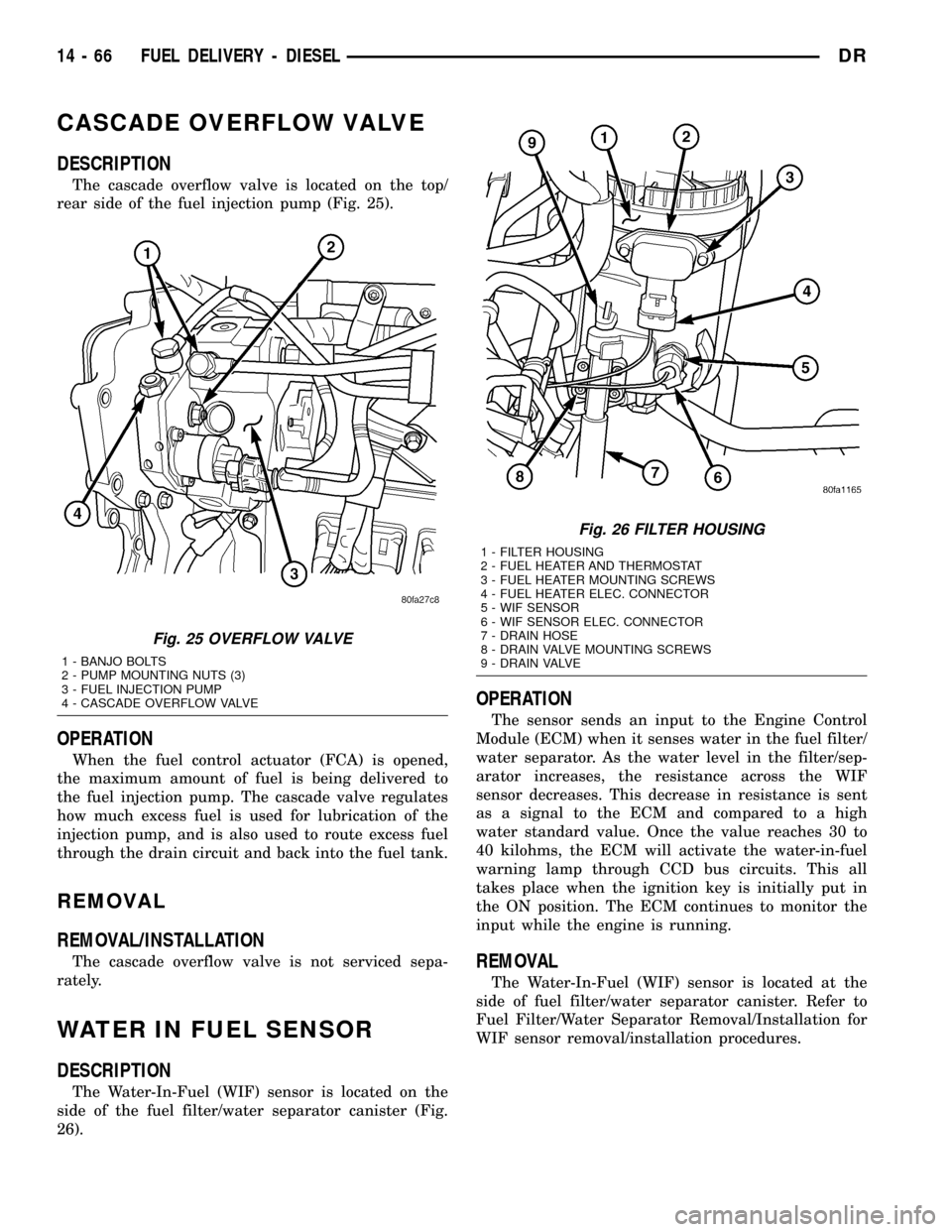
rear side of the fuel injection pump (Fig. 25).
OPERATION
When the fuel control actuator (FCA) is opened,
the maximum amount of fuel is being delivered to
the fuel injection pump. The cascade valve regulates
how much excess fuel is used for lubrication of the
injection pump, and is also used to route excess fuel
through the drain circuit and back into the fuel tank.
REMOVAL
REMOVAL/INSTALLATION
The cascade overflow valve is not serviced sepa-
rately.
WATER IN FUEL SENSOR
DESCRIPTION
The Water-In-Fuel (WIF) sensor is located on the
side of the fuel filter/water separator canister (Fig.
26).
OPERATION
The sensor sends an input to the Engine Control
Module (ECM) when it senses water in the fuel filter/
water separator. As the water level in the filter/sep-
arator increases, the resistance across the WIF
sensor decreases. This decrease in resistance is sent
as a signal to the ECM and compared to a high
water standard value. Once the value reaches 30 to
40 kilohms, the ECM will activate the water-in-fuel
warning lamp through CCD bus circuits. This all
takes place when the ignition key is initially put in
the ON position. The ECM continues to monitor the
input while the engine is running.
REMOVAL
The Water-In-Fuel (WIF) sensor is located at the
side of fuel filter/water separator canister. Refer to
Fuel Filter/Water Separator Removal/Installation for
WIF sensor removal/installation procedures.
Fig. 25 OVERFLOW VALVE
1 - BANJO BOLTS
2 - PUMP MOUNTING NUTS (3)
3 - FUEL INJECTION PUMP
4 - CASCADE OVERFLOW VALVE
Fig. 26 FILTER HOUSING
1 - FILTER HOUSING
2 - FUEL HEATER AND THERMOSTAT
3 - FUEL HEATER MOUNTING SCREWS
4 - FUEL HEATER ELEC. CONNECTOR
5 - WIF SENSOR
6 - WIF SENSOR ELEC. CONNECTOR
7 - DRAIN HOSE
8 - DRAIN VALVE MOUNTING SCREWS
9 - DRAIN VALVE
14 - 66 FUEL DELIVERY - DIESELDR
Page 1636 of 2627

FUEL DRAIN CIRCUIT
OPERATION
The Fuel Drain Circuit incorporates several
sources of fuel return. Fuel travels from the fuel tank
to the fuel transfer pump and is forced through the
fuel filter. This fuel then travels into the fuel injec-
tion pump. It then goes to a fuel drain line and
returns back to the fuel tank.
The fuel that flows to the fuel pump is pressurized
by a gear pump and internally transferred to the fuel
injection pump. At this point the fuel is channeled
into two passages. One passage sends fuel to the
FCA (Fuel Control Actuator). The other passage
sends fuel to the cascade overflow valve. The over-
flow valve sends some fuel to a lubrication passage.
The rest of the fuel is sent to a drain passage which
connects to an external fuel line.Fuel that travels through the FCA is pressurized
by the fuel injection pump and sent through an
external high pressure fuel line to the fuel rail. At
the fuel rail, fuel is sent to the fuel injectors. If fuel
pressure in the fuel rail becomes excessive, the pres-
sure limiting valve opens and sends fuel through an
external fuel line.
At the fuel injector, fuel that is not injected is used
for lubrication of the fuel injectors. This fuel then
travels through an internal passage that is connected
to the rear of the cylinder head, an then into an
external fuel line. This line is connected to the vehi-
cles fuel return line, and returns excess fuel to the
fuel tank.
DRFUEL DELIVERY - DIESEL 14 - 67
Page 1644 of 2627
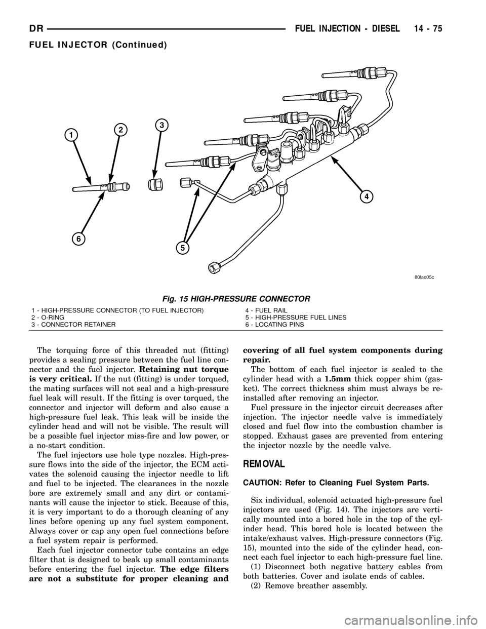
The torquing force of this threaded nut (fitting)
provides a sealing pressure between the fuel line con-
nector and the fuel injector.Retaining nut torque
is very critical.If the nut (fitting) is under torqued,
the mating surfaces will not seal and a high-pressure
fuel leak will result. If the fitting is over torqued, the
connector and injector will deform and also cause a
high-pressure fuel leak. This leak will be inside the
cylinder head and will not be visible. The result will
be a possible fuel injector miss-fire and low power, or
a no-start condition.
The fuel injectors use hole type nozzles. High-pres-
sure flows into the side of the injector, the ECM acti-
vates the solenoid causing the injector needle to lift
and fuel to be injected. The clearances in the nozzle
bore are extremely small and any dirt or contami-
nants will cause the injector to stick. Because of this,
it is very important to do a thorough cleaning of any
lines before opening up any fuel system component.
Always cover or cap any open fuel connections before
a fuel system repair is performed.
Each fuel injector connector tube contains an edge
filter that is designed to beak up small contaminants
before entering the fuel injector.The edge filters
are not a substitute for proper cleaning andcovering of all fuel system components during
repair.
The bottom of each fuel injector is sealed to the
cylinder head with a1.5mmthick copper shim (gas-
ket). The correct thickness shim must always be re-
installed after removing an injector.
Fuel pressure in the injector circuit decreases after
injection. The injector needle valve is immediately
closed and fuel flow into the combustion chamber is
stopped. Exhaust gases are prevented from entering
the injector nozzle by the needle valve.
REMOVAL
CAUTION: Refer to Cleaning Fuel System Parts.
Six individual, solenoid actuated high-pressure fuel
injectors are used (Fig. 14). The injectors are verti-
cally mounted into a bored hole in the top of the cyl-
inder head. This bored hole is located between the
intake/exhaust valves. High-pressure connectors (Fig.
15), mounted into the side of the cylinder head, con-
nect each fuel injector to each high-pressure fuel line.
(1) Disconnect both negative battery cables from
both batteries. Cover and isolate ends of cables.
(2) Remove breather assembly.
Fig. 15 HIGH-PRESSURE CONNECTOR
1 - HIGH-PRESSURE CONNECTOR (TO FUEL INJECTOR)
2 - O-RING
3 - CONNECTOR RETAINER4 - FUEL RAIL
5 - HIGH-PRESSURE FUEL LINES
6 - LOCATING PINS
DRFUEL INJECTION - DIESEL 14 - 75
FUEL INJECTOR (Continued)
Page 1648 of 2627
(8) Connect battery cables to both batteries.
(9) Start engine and check for leaks.
INLET AIR TEMPERATURE
SENSOR/PRESSURE SENSOR
DESCRIPTION
The combination, dual function Inlet Air Tempera-
ture/Pressure Sensor is located on the air cleaner (fil-
ter) cover.
OPERATION
The Inlet Air Temperature/Pressure Sensor is a
combination dual-function sensor. The sensor element
extends into the intake air stream at the top of the
air filter housing. Ambient air temperature as well as
barometric pressure is monitored by this sensor. The
Engine Control Module (ECM) monitors signals from
this sensor.
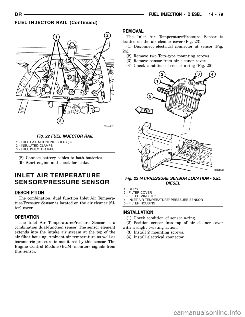
REMOVAL
The Inlet Air Temperature/Pressure Sensor is
located on the air cleaner cover (Fig. 23).
(1) Disconnect electrical connector at sensor (Fig.
24).
(2) Remove two Torx-type mounting screws.
(3) Remove sensor from air cleaner cover.
(4) Check condition of sensor o-ring (Fig. 25).
INSTALLATION
(1) Check condition of sensor o-ring.
(2) Position sensor into top of air cleaner cover
with a slight twisting action.
(3) Install 2 mounting screws.
(4) Install electrical connector.
Fig. 22 FUEL INJECTOR RAIL
1 - FUEL RAIL MOUNTING BOLTS (3)
2 - INSULATED CLAMPS
3 - FUEL INJECTOR RAIL
Fig. 23 IAT/PRESSURE SENSOR LOCATION - 5.9L
DIESEL
1 - CLIPS
2 - FILTER COVER
3 - FILTER MINDERŸ
4 - INLET AIR TEMPERATURE/ PRESSURE SENSOR
5 - FILTER HOUSING
DRFUEL INJECTION - DIESEL 14 - 79
FUEL INJECTOR RAIL (Continued)
Page 1649 of 2627
INTAKE AIR HEATER
DESCRIPTION
The intake manifold air heater element assembly
is located in the top of the intake manifold.
OPERATION
The air heater elements are used to heat incoming
air to the intake manifold. This is done to help
engine starting and improve driveability with cool or
cold outside temperatures.
Electrical supply for the 2 air heater elements is
controlled by the Engine Control Module (ECM)
through the 2 air heater relays. Refer to Intake Man-
ifold Air Heater Relays for more information.
Two heavy-duty cables connect the 2 air heater ele-
ments to the 2 air heater relays. Each of these cables
will supply approximately 95 amps at 12 volts to an
individual heating element within the heater block
assembly.
Refer to the Powertrain Diagnostic Procedures
manual for electrical operation and complete descrip-
tion of the intake heaters, including pre-heat and
post-heat cycles.
REMOVAL
If servicing either of the heater elements, the
entire block/element assembly must be replaced.
(1) Disconnect both negative battery cables at both
batteries. Cover and isolate ends of both cables.
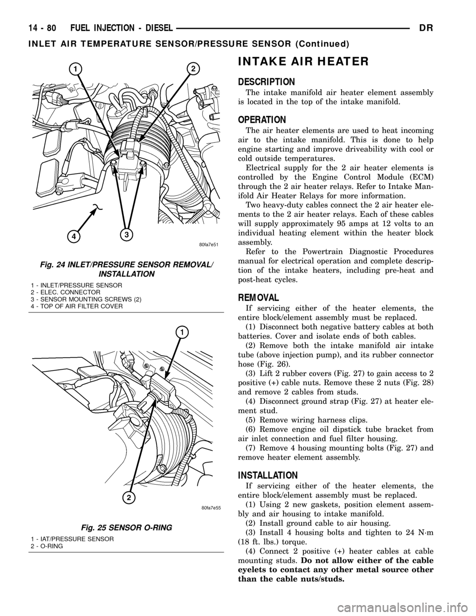
(2) Remove both the intake manifold air intake
tube (above injection pump), and its rubber connector
hose (Fig. 26).
(3) Lift 2 rubber covers (Fig. 27) to gain access to 2
positive (+) cable nuts. Remove these 2 nuts (Fig. 28)
and remove 2 cables from studs.
(4) Disconnect ground strap (Fig. 27) at heater ele-
ment stud.
(5) Remove wiring harness clips.
(6) Remove engine oil dipstick tube bracket from
air inlet connection and fuel filter housing.
(7) Remove 4 housing mounting bolts (Fig. 27) and
remove heater element assembly.
INSTALLATION
If servicing either of the heater elements, the
entire block/element assembly must be replaced.
(1) Using 2 new gaskets, position element assem-
bly and air housing to intake manifold.
(2) Install ground cable to air housing.
(3) Install 4 housing bolts and tighten to 24 N´m
(18 ft. lbs.) torque.
(4) Connect 2 positive (+) heater cables at cable
mounting studs.Do not allow either of the cable
eyelets to contact any other metal source other
than the cable nuts/studs.
Fig. 24 INLET/PRESSURE SENSOR REMOVAL/
INSTALLATION
1 - INLET/PRESSURE SENSOR
2 - ELEC. CONNECTOR
3 - SENSOR MOUNTING SCREWS (2)
4 - TOP OF AIR FILTER COVER
Fig. 25 SENSOR O-RING
1 - IAT/PRESSURE SENSOR
2 - O-RING
14 - 80 FUEL INJECTION - DIESELDR
INLET AIR TEMPERATURE SENSOR/PRESSURE SENSOR (Continued)
Page 2569 of 2627
²Engine RPMÐ A live reading of engine RPM
to aid the user in accessing the Similar Conditions
Window.
²Adaptive Memory FactorÐ The PCM utilizes
both Short Term Compensation and Long Term Adap-
tive to calculate the Adaptive Memory Factor for
total fuel correction.
²Upstream O2S VoltsÐ A live reading of the
Oxygen Sensor to indicate its performance. For
example, stuck lean, stuck rich, etc.
²SCW Time in Window (Similar Conditions
Window Time in Window)Ð A timer used by the
PCM that indicates that, after all Similar Conditions
have been met, if there has been enough good engine
running time in the SCW without failure detected.
This timer is used to increment a Good Trip.
²Fuel System Good Trip CounterÐATrip
Counter used to turn OFF the MIL for Fuel System
DTCs. To increment a Fuel System Good Trip, the
engine must be in the Similar Conditions Window,
Adaptive Memory Factor must be less than cali-
brated threshold and the Adaptive Memory Factor
must stay below that threshold for a calibrated
amount of time.
²Test Done This TripÐ Indicates that the
monitor has already been run and completed during
the current trip.
MISFIRE
²Same Misfire Warm-Up StateÐ Indicates if
the misfire occurred when the engine was warmed up
(above 160É F).
²In Similar Misfire WindowÐ An indicator
that 'Absolute MAP When Misfire Occurred' and
'RPM When Misfire Occurred' are all in the same
range when the failure occurred. Indicated by switch-
ing from 'NO' to 'YES'.
²Absolute MAP When Misfire OccurredÐ
The stored MAP reading at the time of failure.
Informs the user at what engine load the failure
occurred.
²Absolute MAPÐ A live reading of engine load
to aid the user in accessing the Similar Conditions
Window.
²RPM When Misfire OccurredÐ The stored
RPM reading at the time of failure. Informs the user
at what engine RPM the failure occurred.
²Engine RPMÐ A live reading of engine RPM
to aid the user in accessing the Similar Conditions
Window.
²Adaptive Memory FactorÐ The PCM utilizes
both Short Term Compensation and Long Term Adap-
tive to calculate the Adaptive Memory Factor for
total fuel correction.
²200 Rev CounterÐ Counts 0±100 720 degree
cycles.²SCW Cat 200 Rev CounterÐ Counts when in
similar conditions.
²SCW FTP 1000 Rev CounterÐ Counts 0±4
when in similar conditions.
²Misfire Good Trip CounterÐ Counts up to
three to turn OFF the MIL.
²Misfire DataÐ Data collected during test.
²Test Done This TripÐ Indicates YES when the
test is done.
OPERATION - NON-MONITORED CIRCUITS
The PCM does not monitor the following circuits,
systems and conditions that could have malfunctions
causing driveability problems. The PCM might not
store diagnostic trouble codes for these conditions.
However, problems with these systems may cause the
PCM to store diagnostic trouble codes for other sys-
tems or components.EXAMPLE:a fuel pressure
problem will not register a fault directly, but could
cause a rich/lean condition or misfire. This could
cause the PCM to store an oxygen sensor or misfire
diagnostic trouble code
FUEL PRESSURE
The fuel pressure regulator controls fuel system
pressure. The PCM cannot detect a clogged fuel
pump inlet filter, clogged in-line fuel filter, or a
pinched fuel supply or return line. However, these
could result in a rich or lean condition causing the
PCM to store an oxygen sensor or fuel system diag-
nostic trouble code.
SECONDARY IGNITION CIRCUIT
The PCM cannot detect an inoperative ignition coil,
fouled or worn spark plugs, ignition cross firing, or
open spark plug cables.
CYLINDER COMPRESSION
The PCM cannot detect uneven, low, or high engine
cylinder compression.
EXHAUST SYSTEM
The PCM cannot detect a plugged, restricted or
leaking exhaust system, although it may set a fuel
system fault.
FUEL INJECTOR MECHANICAL MALFUNCTIONS
The PCM cannot determine if a fuel injector is
clogged, the needle is sticking or if the wrong injector
is installed. However, these could result in a rich or
lean condition causing the PCM to store a diagnostic
trouble code for either misfire, an oxygen sensor, or
the fuel system.
25 - 8 EMISSIONS CONTROLDR
EMISSIONS CONTROL (Continued)