power train control module DODGE RAM 1500 1998 2.G Manual Online
[x] Cancel search | Manufacturer: DODGE, Model Year: 1998, Model line: RAM 1500, Model: DODGE RAM 1500 1998 2.GPages: 2627
Page 1137 of 2627
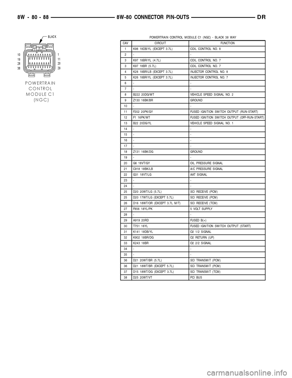
POWERTRAIN CONTROL MODULE C1 (NGC) - BLACK 38 WAY
CAV CIRCUIT FUNCTION
1 K98 18DB/YL (EXCEPT 3.7L) COIL CONTROL NO. 8
2- -
3 K97 18BR/YL (4.7L) COIL CONTROL NO. 7
3 K97 18BR (5.7L) COIL CONTROL NO. 7
4 K28 18BR/LB (EXCEPT 3.7L) INJECTOR CONTROL NO. 8
5 K26 18BR/YL (EXCEPT 3.7L) INJECTOR CONTROL NO. 7
6- -
7- -
8 B222 20DG/WT VEHICLE SPEED SIGNAL NO. 2
9 Z130 16BK/BR GROUND
10 - -
11 F202 20PK/GY FUSED IGNITION SWITCH OUTPUT (RUN-START)
12 F1 16PK/WT FUSED IGNITION SWITCH OUTPUT (OFF-RUN-START)
13 B22 20DG/YL VEHICLE SPEED SIGNAL NO. 1
14 - -
15 - -
16 - -
17 - -
18 Z131 16BK/DG GROUND
19 - -
20 G6 18VT/GY OIL PRESSURE SIGNAL
21 C918 18BK/LB A/C PRESSURE SIGNAL
22 G31 18VT/LG AAT SIGNAL
23 - -
24 - -
25 D20 20WT/LG (5.7L) SCI RECEIVE (PCM)
25 D20 17WT/LG (EXCEPT 5.7L) SCI RECEIVE (PCM)
26 D16 18WT/OR (EXCEPT 3.7L M/T) SCI RECEIVE (TCM)
27 F856 18YL/PK 5 VOLT SUPPLY
28 - -
29 A919 20RD FUSED B(+)
30 T751 16YL FUSED IGNITION SWITCH OUTPUT (START)
31 K141 18DB/YL O2 1/2 SIGNAL
32 K902 18BR/DG O2 RETURN (UP)
33 K243 18BR O2 2/2 SIGNAL
34 - -
35 - -
36 D21 20WT/BR (5.7L) SCI TRANSMIT (PCM)
36 D21 18WT/BR (EXCEPT 5.7L) SCI TRANSMIT (PCM)
37 D15 18WT/DG (EXCEPT 3.7L) SCI TRANSMIT (TCM)
38 D25 20WT/VT PCI BUS
8W - 80 - 88 8W-80 CONNECTOR PIN-OUTSDR
Page 1138 of 2627
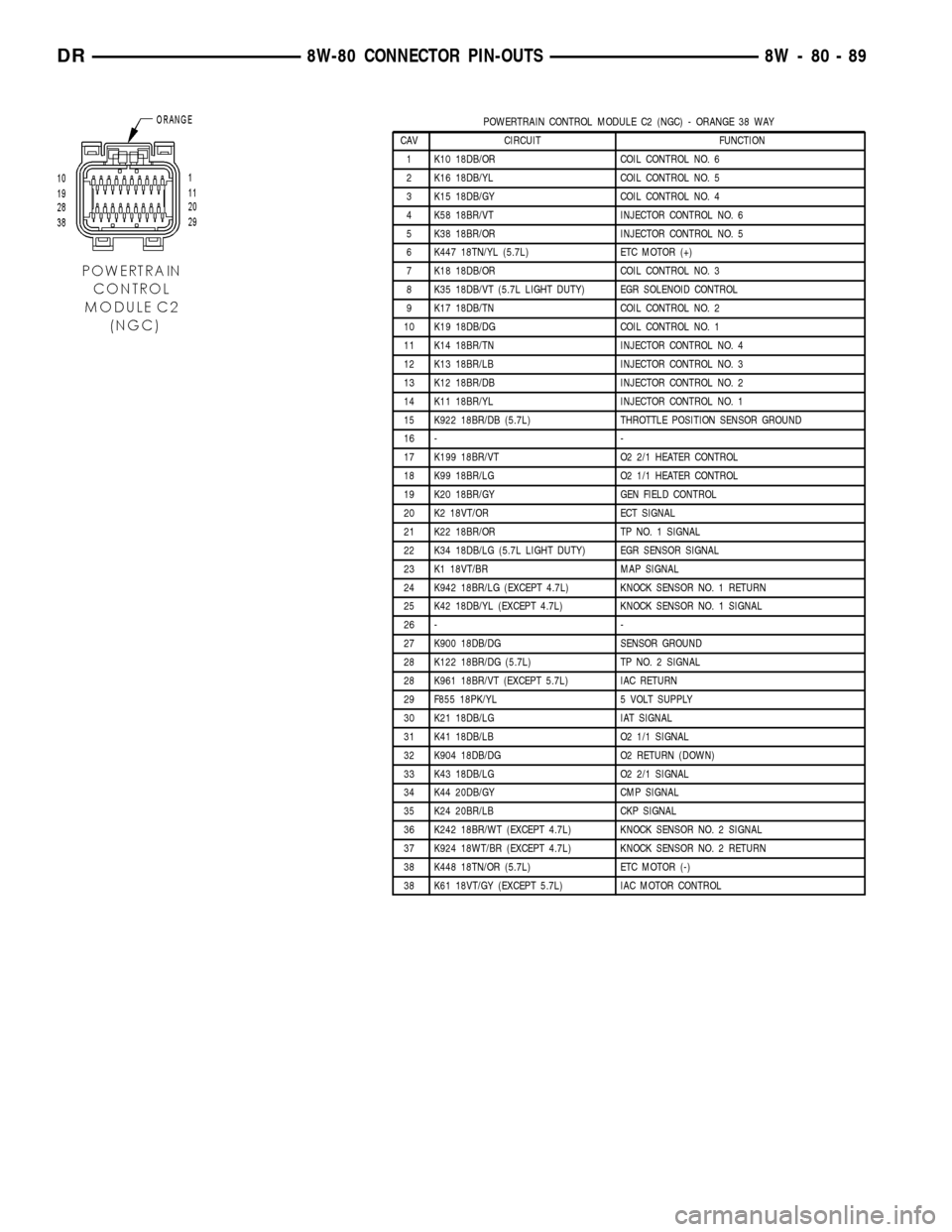
POWERTRAIN CONTROL MODULE C2 (NGC) - ORANGE 38 WAY
CAV CIRCUIT FUNCTION
1 K10 18DB/OR COIL CONTROL NO. 6
2 K16 18DB/YL COIL CONTROL NO. 5
3 K15 18DB/GY COIL CONTROL NO. 4
4 K58 18BR/VT INJECTOR CONTROL NO. 6
5 K38 18BR/OR INJECTOR CONTROL NO. 5
6 K447 18TN/YL (5.7L) ETC MOTOR (+)
7 K18 18DB/OR COIL CONTROL NO. 3
8 K35 18DB/VT (5.7L LIGHT DUTY) EGR SOLENOID CONTROL
9 K17 18DB/TN COIL CONTROL NO. 2
10 K19 18DB/DG COIL CONTROL NO. 1
11 K14 18BR/TN INJECTOR CONTROL NO. 4
12 K13 18BR/LB INJECTOR CONTROL NO. 3
13 K12 18BR/DB INJECTOR CONTROL NO. 2
14 K11 18BR/YL INJECTOR CONTROL NO. 1
15 K922 18BR/DB (5.7L) THROTTLE POSITION SENSOR GROUND
16 - -
17 K199 18BR/VT O2 2/1 HEATER CONTROL
18 K99 18BR/LG O2 1/1 HEATER CONTROL
19 K20 18BR/GY GEN FIELD CONTROL
20 K2 18VT/OR ECT SIGNAL
21 K22 18BR/OR TP NO. 1 SIGNAL
22 K34 18DB/LG (5.7L LIGHT DUTY) EGR SENSOR SIGNAL
23 K1 18VT/BR MAP SIGNAL
24 K942 18BR/LG (EXCEPT 4.7L) KNOCK SENSOR NO. 1 RETURN
25 K42 18DB/YL (EXCEPT 4.7L) KNOCK SENSOR NO. 1 SIGNAL
26 - -
27 K900 18DB/DG SENSOR GROUND
28 K122 18BR/DG (5.7L) TP NO. 2 SIGNAL
28 K961 18BR/VT (EXCEPT 5.7L) IAC RETURN
29 F855 18PK/YL 5 VOLT SUPPLY
30 K21 18DB/LG IAT SIGNAL
31 K41 18DB/LB O2 1/1 SIGNAL
32 K904 18DB/DG O2 RETURN (DOWN)
33 K43 18DB/LG O2 2/1 SIGNAL
34 K44 20DB/GY CMP SIGNAL
35 K24 20BR/LB CKP SIGNAL
36 K242 18BR/WT (EXCEPT 4.7L) KNOCK SENSOR NO. 2 SIGNAL
37 K924 18WT/BR (EXCEPT 4.7L) KNOCK SENSOR NO. 2 RETURN
38 K448 18TN/OR (5.7L) ETC MOTOR (-)
38 K61 18VT/GY (EXCEPT 5.7L) IAC MOTOR CONTROL
DR8W-80 CONNECTOR PIN-OUTS 8W - 80 - 89
Page 1139 of 2627
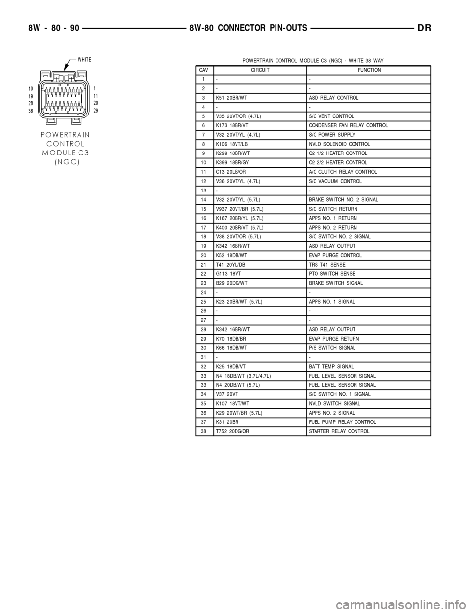
POWERTRAIN CONTROL MODULE C3 (NGC) - WHITE 38 WAY
CAV CIRCUIT FUNCTION
1- -
2- -
3 K51 20BR/WT ASD RELAY CONTROL
4- -
5 V35 20VT/OR (4.7L) S/C VENT CONTROL
6 K173 18BR/VT CONDENSER FAN RELAY CONTROL
7 V32 20VT/YL (4.7L) S/C POWER SUPPLY
8 K106 18VT/LB NVLD SOLENOID CONTROL
9 K299 18BR/WT O2 1/2 HEATER CONTROL
10 K399 18BR/GY O2 2/2 HEATER CONTROL
11 C13 20LB/OR A/C CLUTCH RELAY CONTROL
12 V36 20VT/YL (4.7L) S/C VACUUM CONTROL
13 - -
14 V32 20VT/YL (5.7L) BRAKE SWITCH NO. 2 SIGNAL
15 V937 20VT/BR (5.7L) S/C SWITCH RETURN
16 K167 20BR/YL (5.7L) APPS NO. 1 RETURN
17 K400 20BR/VT (5.7L) APPS NO. 2 RETURN
18 V38 20VT/OR (5.7L) S/C SWITCH NO. 2 SIGNAL
19 K342 16BR/WT ASD RELAY OUTPUT
20 K52 18DB/WT EVAP PURGE CONTROL
21 T41 20YL/DB TRS T41 SENSE
22 G113 18VT PTO SWITCH SENSE
23 B29 20DG/WT BRAKE SWITCH SIGNAL
24 - -
25 K23 20BR/WT (5.7L) APPS NO. 1 SIGNAL
26 - -
27 - -
28 K342 16BR/WT ASD RELAY OUTPUT
29 K70 18DB/BR EVAP PURGE RETURN
30 K66 18DB/WT P/S SWITCH SIGNAL
31 - -
32 K25 18DB/VT BATT TEMP SIGNAL
33 N4 18DB/WT (3.7L/4.7L) FUEL LEVEL SENSOR SIGNAL
33 N4 20DB/WT (5.7L) FUEL LEVEL SENSOR SIGNAL
34 V37 20VT S/C SWITCH NO. 1 SIGNAL
35 K107 18VT/WT NVLD SWITCH SIGNAL
36 K29 20WT/BR (5.7L) APPS NO. 2 SIGNAL
37 K31 20BR FUEL PUMP RELAY CONTROL
38 T752 20DG/OR STARTER RELAY CONTROL
8W - 80 - 90 8W-80 CONNECTOR PIN-OUTSDR
Page 1140 of 2627

POWERTRAIN CONTROL MODULE C4 (NGC) - GREEN 38 WAY
CAV CIRCUIT FUNCTION
1 T60 18YL/GY OVERDRIVE SOLENOID CONTROL
2 T259 18YL/DG 4C SOLENOID CONTROL
3- -
4 T118 18DG MS SOLENOID CONTROL
5- -
6 T219 18YL/LG 2C SOLENOID CONTROL
7- -
8 T59 18YL/LB UNDERDRIVE SOLENOID CONTROL
9- -
10 T20 18DG/WT L/R SOLENOID CONTROL
11 T140 18YL/GY PRESSURE CONTROL SOLENOID CONTROL
12 Z908 18BK GROUND
13 Z977 18BK GROUND
14 Z904 18BK (A/T) GROUND
15 T1 18DG/LB TRS T1 SENSE
16 T3 18DG/DB TRS T3 SENSE
17 T6 18DG TOW/HAUL OVERDRIVE OFF SWITCH SENSE
18 T515 20YL/DB TRANSMISSION CONTROL RELAY CONTROL
19 T16 18YL/OR TRANSMISSION CONTROL RELAY OUTPUT
20 T48 18BR/YL 4C PRESSURE SWITCH SENSE
21 T29 18YL/WT UNDERDRIVE PRESSURE SWITCH SENSE
22 T9 18DG/TN OVERDRIVE PRESSURE SWITCH SENSE
23 - -
24 - -
25 - -
26 T4 18DG/LB TRS T2 SENSE
27 - -
28 T16 18YL/OR TRANSMISSION CONTROL RELAY OUTPUT
29 T50 18YL/TN LOW/REVERSE PRESSURE SWITCH SENSE
30 T147 18DG/YL 2C PRESSURE SWITCH SENSE
31 T38 18YL/BR LINE PRESSURE SENSOR SIGNAL
32 T14 18DG/BR OUTPUT SPEED SENSOR SIGNAL
33 T52 18DG/OR INPUT SPEED SENSOR SIGNAL
34 T13 18DG/VT SPEED SENSOR GROUND
35 T54 18DG/OR TRANSMISSION TEMPERATURE SENSOR SIGNAL
36 - -
37 T42 18DG/YL TRS T42 SENSE
38 T16 18YL/OR TRANSMISSION CONTROL RELAY OUTPUT
DR8W-80 CONNECTOR PIN-OUTS 8W - 80 - 91
Page 1159 of 2627
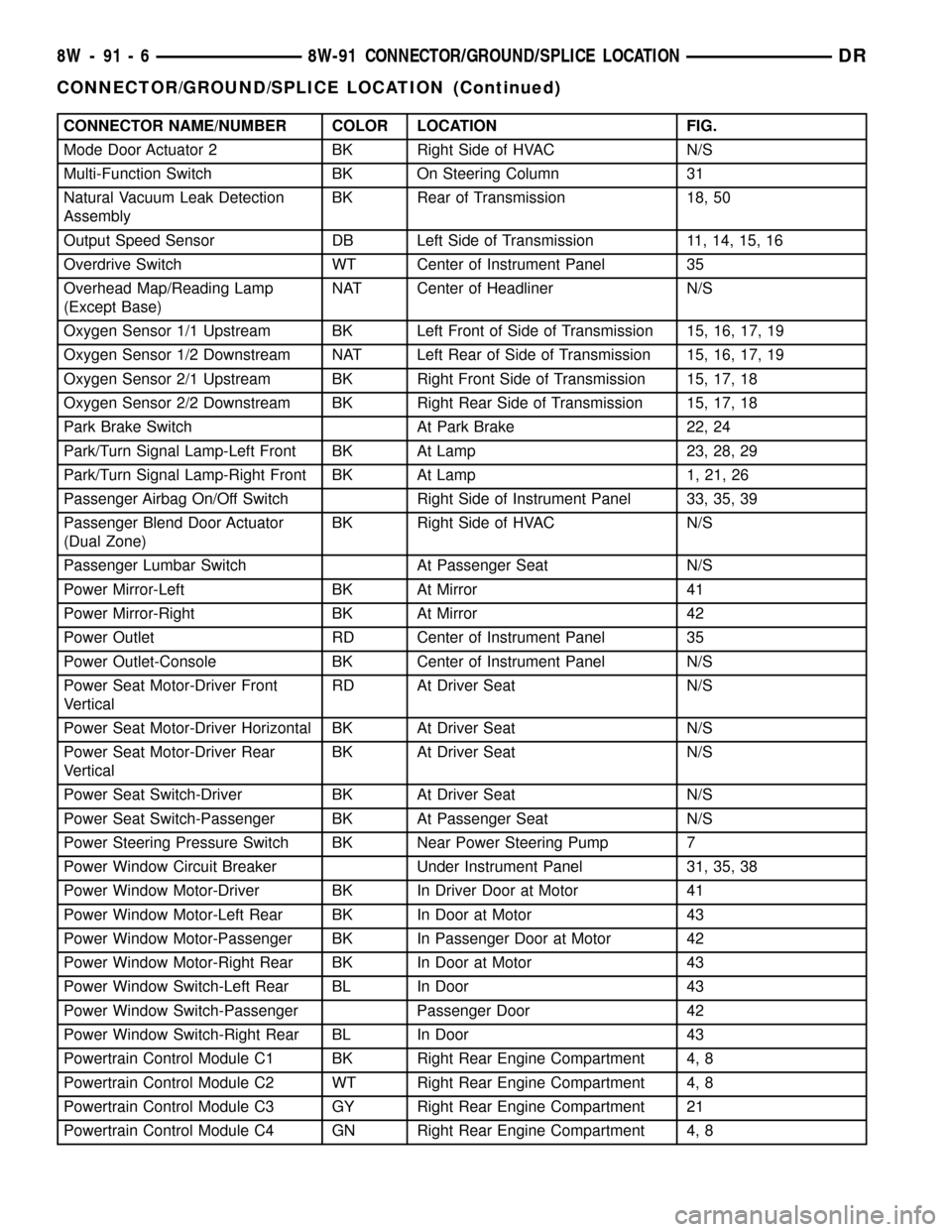
CONNECTOR NAME/NUMBER COLOR LOCATION FIG.
Mode Door Actuator 2 BK Right Side of HVAC N/S
Multi-Function Switch BK On Steering Column 31
Natural Vacuum Leak Detection
AssemblyBK Rear of Transmission 18, 50
Output Speed Sensor DB Left Side of Transmission 11, 14, 15, 16
Overdrive Switch WT Center of Instrument Panel 35
Overhead Map/Reading Lamp
(Except Base)NAT Center of Headliner N/S
Oxygen Sensor 1/1 Upstream BK Left Front of Side of Transmission 15, 16, 17, 19
Oxygen Sensor 1/2 Downstream NAT Left Rear of Side of Transmission 15, 16, 17, 19
Oxygen Sensor 2/1 Upstream BK Right Front Side of Transmission 15, 17, 18
Oxygen Sensor 2/2 Downstream BK Right Rear Side of Transmission 15, 17, 18
Park Brake Switch At Park Brake 22, 24
Park/Turn Signal Lamp-Left Front BK At Lamp 23, 28, 29
Park/Turn Signal Lamp-Right Front BK At Lamp 1, 21, 26
Passenger Airbag On/Off Switch Right Side of Instrument Panel 33, 35, 39
Passenger Blend Door Actuator
(Dual Zone)BK Right Side of HVAC N/S
Passenger Lumbar Switch At Passenger Seat N/S
Power Mirror-Left BK At Mirror 41
Power Mirror-Right BK At Mirror 42
Power Outlet RD Center of Instrument Panel 35
Power Outlet-Console BK Center of Instrument Panel N/S
Power Seat Motor-Driver Front
VerticalRD At Driver Seat N/S
Power Seat Motor-Driver Horizontal BK At Driver Seat N/S
Power Seat Motor-Driver Rear
VerticalBK At Driver Seat N/S
Power Seat Switch-Driver BK At Driver Seat N/S
Power Seat Switch-Passenger BK At Passenger Seat N/S
Power Steering Pressure Switch BK Near Power Steering Pump 7
Power Window Circuit Breaker Under Instrument Panel 31, 35, 38
Power Window Motor-Driver BK In Driver Door at Motor 41
Power Window Motor-Left Rear BK In Door at Motor 43
Power Window Motor-Passenger BK In Passenger Door at Motor 42
Power Window Motor-Right Rear BK In Door at Motor 43
Power Window Switch-Left Rear BL In Door 43
Power Window Switch-Passenger Passenger Door 42
Power Window Switch-Right Rear BL In Door 43
Powertrain Control Module C1 BK Right Rear Engine Compartment 4, 8
Powertrain Control Module C2 WT Right Rear Engine Compartment 4, 8
Powertrain Control Module C3 GY Right Rear Engine Compartment 21
Powertrain Control Module C4 GN Right Rear Engine Compartment 4, 8
8W - 91 - 6 8W-91 CONNECTOR/GROUND/SPLICE LOCATIONDR
CONNECTOR/GROUND/SPLICE LOCATION (Continued)
Page 1216 of 2627

8W-97 POWER DISTRIBUTION
TABLE OF CONTENTS
page page
POWER DISTRIBUTION
DESCRIPTION..........................1
OPERATION............................1
SPECIAL TOOLS
POWER DISTRIBUTION SYSTEMS.........2
CIGAR LIGHTER OUTLET
DESCRIPTION..........................2
OPERATION............................2
DIAGNOSIS AND TESTING - CIGAR LIGHTER
OUTLET.............................2
INTEGRATED POWER MODULE
DESCRIPTION..........................3
OPERATION............................3
REMOVAL.............................3
INSTALLATION..........................4
FRONT CONTROL MODULE
DESCRIPTION..........................5OPERATION............................5
DIAGNOSIS AND TESTING - FRONT
CONTROL MODULE....................5
REMOVAL.............................6
INSTALLATION..........................6
IOD FUSE
DESCRIPTION..........................6
OPERATION............................6
REMOVAL.............................7
INSTALLATION..........................7
POWER OUTLET
DESCRIPTION..........................7
OPERATION............................7
DIAGNOSIS AND TESTING - POWER
OUTLET.............................7
REMOVAL.............................8
INSTALLATION..........................8
POWER DISTRIBUTION
DESCRIPTION
This group covers the various standard and
optional power distribution components used on this
model. The power distribution system for this vehicle
consists of the following components:
²Integrated Power Module (IPM)
²Front Control Module (FCM)
²Power Distribution Center (PDC)
²Power Outlets
²Cigar Lighter Outlets
²Relays
Refer to Wiring Diagrams for complete circuit sche-
matics.
The power distribution system also incorporates
various types of circuit control and protection fea-
tures, including:
²Automatic resetting circuit breakers
²Blade-type fuses
²Cartridge fuses
²Relays
Following are general descriptions of the major
components in the power distribution system. See the
owner's manual in the vehicle glove box for more
information on the features and use of all of the
power distribution system components.
OPERATION
The power distribution system for this vehicle is
designed to provide safe, reliable, and centralized dis-
tribution points for the electrical current required to
operate all of the many standard and optional facto-
ry-installed electrical and electronic powertrain,
chassis, safety, security, comfort and convenience sys-
tems. At the same time, the power distribution sys-
tem was designed to provide ready access to these
electrical distribution points for the vehicle techni-
cian to use when conducting diagnosis and repair of
faulty circuits. The power distribution system can
also prove useful for the sourcing of additional elec-
trical circuits that may be required to provide the
electrical current needed to operate many accessories
that the vehicle owner may choose to have installed
in the aftermarket.
DR8W-97 POWER DISTRIBUTION 8W - 97 - 1
Page 1459 of 2627
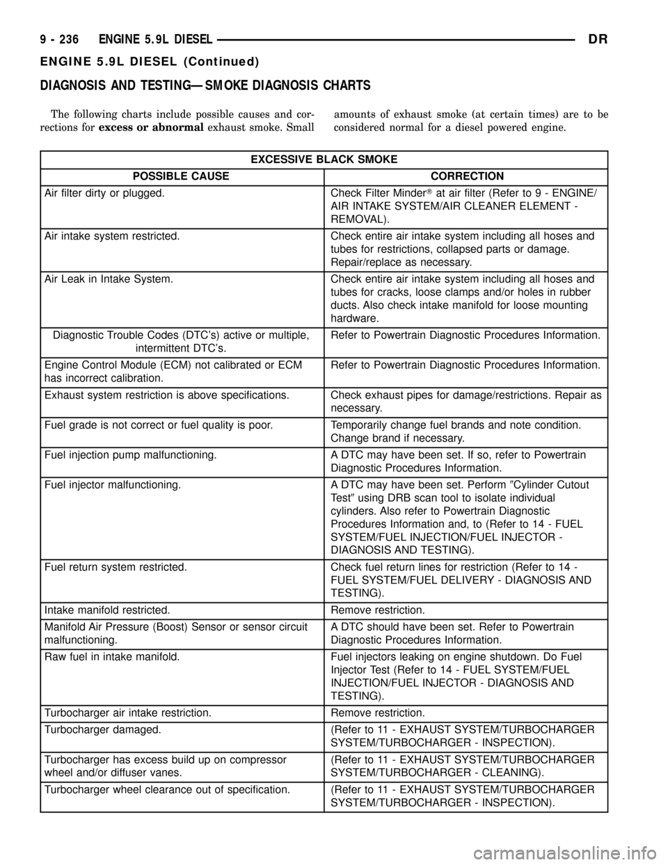
DIAGNOSIS AND TESTINGÐSMOKE DIAGNOSIS CHARTS
The following charts include possible causes and cor-
rections forexcess or abnormalexhaust smoke. Smallamounts of exhaust smoke (at certain times) are to be
considered normal for a diesel powered engine.
EXCESSIVE BLACK SMOKE
POSSIBLE CAUSE CORRECTION
Air filter dirty or plugged. Check Filter MinderTat air filter (Refer to 9 - ENGINE/
AIR INTAKE SYSTEM/AIR CLEANER ELEMENT -
REMOVAL).
Air intake system restricted. Check entire air intake system including all hoses and
tubes for restrictions, collapsed parts or damage.
Repair/replace as necessary.
Air Leak in Intake System. Check entire air intake system including all hoses and
tubes for cracks, loose clamps and/or holes in rubber
ducts. Also check intake manifold for loose mounting
hardware.
Diagnostic Trouble Codes (DTC's) active or multiple,
intermittent DTC's.Refer to Powertrain Diagnostic Procedures Information.
Engine Control Module (ECM) not calibrated or ECM
has incorrect calibration.Refer to Powertrain Diagnostic Procedures Information.
Exhaust system restriction is above specifications. Check exhaust pipes for damage/restrictions. Repair as
necessary.
Fuel grade is not correct or fuel quality is poor. Temporarily change fuel brands and note condition.
Change brand if necessary.
Fuel injection pump malfunctioning. A DTC may have been set. If so, refer to Powertrain
Diagnostic Procedures Information.
Fuel injector malfunctioning. A DTC may have been set. Perform9Cylinder Cutout
Test9using DRB scan tool to isolate individual
cylinders. Also refer to Powertrain Diagnostic
Procedures Information and, to (Refer to 14 - FUEL
SYSTEM/FUEL INJECTION/FUEL INJECTOR -
DIAGNOSIS AND TESTING).
Fuel return system restricted. Check fuel return lines for restriction (Refer to 14 -
FUEL SYSTEM/FUEL DELIVERY - DIAGNOSIS AND
TESTING).
Intake manifold restricted. Remove restriction.
Manifold Air Pressure (Boost) Sensor or sensor circuit
malfunctioning.A DTC should have been set. Refer to Powertrain
Diagnostic Procedures Information.
Raw fuel in intake manifold. Fuel injectors leaking on engine shutdown. Do Fuel
Injector Test (Refer to 14 - FUEL SYSTEM/FUEL
INJECTION/FUEL INJECTOR - DIAGNOSIS AND
TESTING).
Turbocharger air intake restriction. Remove restriction.
Turbocharger damaged. (Refer to 11 - EXHAUST SYSTEM/TURBOCHARGER
SYSTEM/TURBOCHARGER - INSPECTION).
Turbocharger has excess build up on compressor
wheel and/or diffuser vanes.(Refer to 11 - EXHAUST SYSTEM/TURBOCHARGER
SYSTEM/TURBOCHARGER - CLEANING).
Turbocharger wheel clearance out of specification. (Refer to 11 - EXHAUST SYSTEM/TURBOCHARGER
SYSTEM/TURBOCHARGER - INSPECTION).
9 - 236 ENGINE 5.9L DIESELDR
ENGINE 5.9L DIESEL (Continued)
Page 1460 of 2627
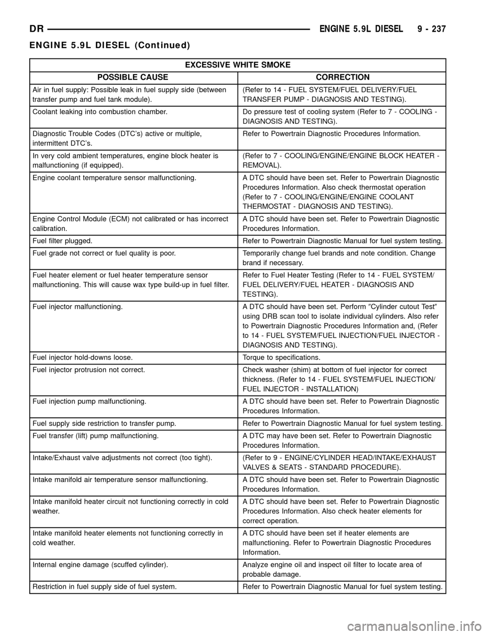
EXCESSIVE WHITE SMOKE
POSSIBLE CAUSE CORRECTION
Air in fuel supply: Possible leak in fuel supply side (between
transfer pump and fuel tank module).(Refer to 14 - FUEL SYSTEM/FUEL DELIVERY/FUEL
TRANSFER PUMP - DIAGNOSIS AND TESTING).
Coolant leaking into combustion chamber. Do pressure test of cooling system (Refer to 7 - COOLING -
DIAGNOSIS AND TESTING).
Diagnostic Trouble Codes (DTC's) active or multiple,
intermittent DTC's.Refer to Powertrain Diagnostic Procedures Information.
In very cold ambient temperatures, engine block heater is
malfunctioning (if equipped).(Refer to 7 - COOLING/ENGINE/ENGINE BLOCK HEATER -
REMOVAL).
Engine coolant temperature sensor malfunctioning. A DTC should have been set. Refer to Powertrain Diagnostic
Procedures Information. Also check thermostat operation
(Refer to 7 - COOLING/ENGINE/ENGINE COOLANT
THERMOSTAT - DIAGNOSIS AND TESTING).
Engine Control Module (ECM) not calibrated or has incorrect
calibration.A DTC should have been set. Refer to Powertrain Diagnostic
Procedures Information.
Fuel filter plugged. Refer to Powertrain Diagnostic Manual for fuel system testing.
Fuel grade not correct or fuel quality is poor. Temporarily change fuel brands and note condition. Change
brand if necessary.
Fuel heater element or fuel heater temperature sensor
malfunctioning. This will cause wax type build-up in fuel filter.Refer to Fuel Heater Testing (Refer to 14 - FUEL SYSTEM/
FUEL DELIVERY/FUEL HEATER - DIAGNOSIS AND
TESTING).
Fuel injector malfunctioning. A DTC should have been set. Perform9Cylinder cutout Test9
using DRB scan tool to isolate individual cylinders. Also refer
to Powertrain Diagnostic Procedures Information and, (Refer
to 14 - FUEL SYSTEM/FUEL INJECTION/FUEL INJECTOR -
DIAGNOSIS AND TESTING).
Fuel injector hold-downs loose. Torque to specifications.
Fuel injector protrusion not correct. Check washer (shim) at bottom of fuel injector for correct
thickness. (Refer to 14 - FUEL SYSTEM/FUEL INJECTION/
FUEL INJECTOR - INSTALLATION)
Fuel injection pump malfunctioning. A DTC should have been set. Refer to Powertrain Diagnostic
Procedures Information.
Fuel supply side restriction to transfer pump. Refer to Powertrain Diagnostic Manual for fuel system testing.
Fuel transfer (lift) pump malfunctioning. A DTC may have been set. Refer to Powertrain Diagnostic
Procedures Information.
Intake/Exhaust valve adjustments not correct (too tight). (Refer to 9 - ENGINE/CYLINDER HEAD/INTAKE/EXHAUST
VALVES & SEATS - STANDARD PROCEDURE).
Intake manifold air temperature sensor malfunctioning. A DTC should have been set. Refer to Powertrain Diagnostic
Procedures Information.
Intake manifold heater circuit not functioning correctly in cold
weather.A DTC should have been set. Refer to Powertrain Diagnostic
Procedures Information. Also check heater elements for
correct operation.
Intake manifold heater elements not functioning correctly in
cold weather.A DTC should have been set if heater elements are
malfunctioning. Refer to Powertrain Diagnostic Procedures
Information.
Internal engine damage (scuffed cylinder). Analyze engine oil and inspect oil filter to locate area of
probable damage.
Restriction in fuel supply side of fuel system. Refer to Powertrain Diagnostic Manual for fuel system testing.
DRENGINE 5.9L DIESEL 9 - 237
ENGINE 5.9L DIESEL (Continued)
Page 1575 of 2627

OPERATION
Fuel Pressure Regulator Operation:The pres-
sure regulator is a mechanical device that is not con-
trolled by engine vacuum or the Powertrain Control
Module (PCM).
The regulator is calibrated to maintain fuel system
operating pressure of approximately 58 2 psi at the
fuel injectors. It contains a diaphragm, calibrated
springs and a fuel return valve. The internal fuel fil-
ter (Fig. 2) is also part of the assembly.
Fuel is supplied to the filter/regulator by the elec-
tric fuel pump through an opening tube at the bot-
tom of filter/regulator (Fig. 2).
The regulator acts as a check valve to maintain
some fuel pressure when the engine is not operating.
This will help to start the engine. A second check
valve is located at the outlet end of the electric fuel
pump.Refer to Fuel Pump - Description and
Operation for more information.
If fuel pressure at the pressure regulator exceeds
approximately 60 psi, an internal diaphragm opens
and excess fuel pressure is routed back into the tank
through the bottom of pressure regulator.
Both fuel filters (at bottom of fuel pump module
and within fuel pressure regulator) are designed for
extended service. They do not require normal sched-
uled maintenance. Filters should only be replaced if
a diagnostic procedure indicates to do so.
FUEL LEVEL SENDING UNIT /
SENSOR
DESCRIPTION
The fuel gauge sending unit (fuel level sensor) is
attached to the side of the fuel pump module. The
sending unit consists of a float, an arm, and a vari-
able resistor track (card).
OPERATION
The fuel pump module has 4 different circuits
(wires). Two of these circuits are used for the fuel
gauge sending unit for fuel gauge operation, and for
certain OBD II emission requirements. The other 2
wires are used for electric fuel pump operation.
For Fuel Gauge Operation:A constant current
source is supplied to the resistor track on the fuel
gauge sending unit. This is fed directly from the
Powertrain Control Module (PCM).NOTE: For
diagnostic purposes, this 12V power source can
only be verified with the circuit opened (fuel
pump module electrical connector unplugged).
With the connectors plugged, output voltages
will vary from about 0.6 volts at FULL, to about
8.6 volts at EMPTY (about 8.6 volts at EMPTY
for Jeep models, and about 7.0 volts at EMPTY
for Dodge Truck models).The resistor track is
used to vary the voltage (resistance) depending on
fuel tank float level. As fuel level increases, the float
and arm move up, which decreases voltage. As fuel
level decreases, the float and arm move down, which
increases voltage. The varied voltage signal is
returned back to the PCM through the sensor return
circuit.
Both of the electrical circuits between the fuel
gauge sending unit and the PCM are hard-wired (not
multi-plexed). After the voltage signal is sent from
the resistor track, and back to the PCM, the PCM
will interpret the resistance (voltage) data and send
a message across the multi-plex bus circuits to the
instrument panel cluster. Here it is translated into
the appropriate fuel gauge level reading. Refer to
Instrument Panel for additional information.
For OBD II Emission Monitor Requirements:
The PCM will monitor the voltage output sent from
the resistor track on the sending unit to indicate fuel
level. The purpose of this feature is to prevent the
OBD II system from recording/setting false misfire
and fuel system monitor diagnostic trouble codes.
The feature is activated if the fuel level in the tank
is less than approximately 15 percent of its rated
capacity. If equipped with a Leak Detection Pump
(EVAP system monitor), this feature will also be acti-
vated if the fuel level in the tank is more than
approximately 85 percent of its rated capacity.
Fig. 2 SIDE VIEW - FILTER/REGULATOR
1 - INTERNAL FUEL FILTER
2 - FUEL FLOW TO FUEL INJECTORS
3 - FUEL FILTER/FUEL PRESSURE REGULATOR
4 - EXCESS FUEL BACK TO TANK
5 - FUEL INLET
6 - RUBBER GROMMET
7 - TOP OF PUMP MODULE
14 - 6 FUEL DELIVERY - GASDR
FUEL FILTER/PRESSURE REGULATOR (Continued)
Page 1592 of 2627

(5) Position APPS assembly to bottom of battery
tray and install 3 bolts. Refer to Torque Specifica-
tions.
(6) Install wheelhouse liner. Refer to Body.
(7)The 5.7L V-8 engine is equipped with a
fully electronic accelerator pedal position sen-
sor. If equipped with a 5.7L, also perform the
following 3 steps:
(a) Connect negative battery cable to battery.
(b) Turn ignition switch ON, but do not crank
engine.
(c) Leave ignition switch ON for a minimum of
10 seconds. This will allow PCM to learn electrical
parameters.
(d) The DRB IIItScan Tool may also be used to
learn electrical parameters. Go to the Miscella-
neous menu, and then select ETC Learn.
(8) If the previous step is not performed, a Diag-
nostic Trouble Code (DTC) will be set.
(9) If necessary, use DRB IIItScan Tool to erase
any Diagnostic Trouble Codes (DTC's) from PCM.
CRANKSHAFT POSITION
SENSOR
DESCRIPTION
3.7L V-6
The Crankshaft Position (CKP) sensor is mounted
into the right rear side of the cylinder block. It is
positioned and bolted into a machined hole.
4.7L V-8
The Crankshaft Position (CKP) sensor is mounted
into the right rear side of the cylinder block. It is
positioned and bolted into a machined hole.
5.7L V-8
The Crankshaft Position (CKP) sensor is mounted
into the right rear side of the cylinder block. It is
positioned and bolted into a machined hole.
OPERATION
3.7L V-6
Engine speed and crankshaft position are provided
through the CKP (Crankshaft Position) sensor. The
sensor generates pulses that are the input sent to the
Powertrain Control Module (PCM). The PCM inter-
prets the sensor input to determine the crankshaft
position. The PCM then uses this position, along with
other inputs, to determine injector sequence and igni-
tion timing.
Fig. 3 APPS REMOVE / INSTALL
1 - BOTTOM OF BATTERY TRAY
2 - ELECTRICAL CONNECTOR
3 - APPS
4 - SWING-DOWN DOOR
5 - CABLE (TO PEDAL)
6 - CABLE RELEASE TAB
Fig. 4 APPS CABLE
1 - APPS LEVER
2 - BALL SOCKET
3 - SWING-DOWN DOOR
4 - CABLE CLIP
5 - CABLE
DRFUEL INJECTION - GAS 14 - 23
ACCELERATOR PEDAL POSITION SENSOR (Continued)