Camshaft specification DODGE RAM 1500 1998 2.G Workshop Manual
[x] Cancel search | Manufacturer: DODGE, Model Year: 1998, Model line: RAM 1500, Model: DODGE RAM 1500 1998 2.GPages: 2627
Page 488 of 2627
IGNITION CONTROL
TABLE OF CONTENTS
page page
IGNITION CONTROL
DESCRIPTION..........................1
SPECIFICATIONS
SPECIFICATIONS - TORQUE - IGNITION....3
ENGINE FIRING ORDER - 3.7L V-6.........4
ENGINE FIRING ORDER ± 4.7L V-8........4
FIRING ORDER / CABLE ROUTING ± 5.7L
V-8 ENGINE...........................4
SPARK PLUG CABLE RESISTANCE........4
SPARK PLUGS........................4
IGNITION COIL RESISTANCE - 3.7L V-6.....5
IGNITION COIL RESISTANCE - 4.7L V-8.....5
IGNITION COIL RESISTANCE - 5.7L V-8.....5
IGNITION TIMING......................5
AUTOMATIC SHUT DOWN RELAY
DESCRIPTION - PCM OUTPUT.............5
OPERATION
OPERATION - PCM OUTPUT.............5
OPERATION - ASD SENSE - PCM INPUT....5
DIAGNOSIS AND TESTING - ASD AND FUEL
PUMP RELAYS........................5
REMOVAL.............................6
INSTALLATION..........................6
CAMSHAFT POSITION SENSOR
DESCRIPTION..........................7
OPERATION............................7
REMOVAL.............................9
INSTALLATION.........................10IGNITION COIL
DESCRIPTION.........................11
OPERATION...........................12
REMOVAL.............................13
INSTALLATION.........................14
KNOCK SENSOR
DESCRIPTION.........................14
OPERATION...........................14
REMOVAL.............................15
INSTALLATION.........................15
SPARK PLUG
DESCRIPTION.........................17
DIAGNOSIS AND TESTING - SPARK PLUG
CONDITIONS.........................17
REMOVAL.............................19
CLEANING
CLEANING AND ADJUSTMENT...........20
INSTALLATION.........................20
IGNITION COIL CAPACITOR
DESCRIPTION.........................21
OPERATION...........................21
REMOVAL.............................21
INSTALLATION.........................21
SPARK PLUG CABLE
DESCRIPTION.........................21
OPERATION...........................21
REMOVAL.............................22
INSTALLATION.........................22
IGNITION CONTROL
DESCRIPTION
The ignition system is controlled by the Powertrain
Control Module (PCM) on all engines.
3.7L V-6 ENGINE
The 3.7L V-6 engine uses a separate ignition coil
for each cylinder. The one-piece coil bolts directly to
the cylinder head. Rubber boots seal the secondary
terminal ends of the coils to the top of all 6 spark
plugs. A separate electrical connector is used for each
coil.
Because of coil design, spark plug cables (second-
ary cables) are not used. A distributor is not used
with the 3.7L engine.
Two knock sensors (one for each cylinder bank) are
used to help control spark knock.The Auto Shutdown (ASD) relay provides battery
voltage to each ignition coil.
The ignition system consists of:
²6 Spark Plugs
²6 Separate Ignition Coils
²2 Knock Sensors
²Powertrain Control Module (PCM)
²Also to be considered part of the ignition system
are certain inputs from the Crankshaft Position,
Camshaft Position, Throttle Position, 2 knock and
MAP Sensors
4.7L V-8 ENGINE
The 4.7L V-8 engine uses a separate ignition coil
for each cylinder. The one-piece coil bolts directly to
the cylinder head. Rubber boots seal the secondary
terminal ends of the coils to the top of all 8 spark
plugs. A separate electrical connector is used for each
coil.
DRIGNITION CONTROL 8I - 1
Page 490 of 2627
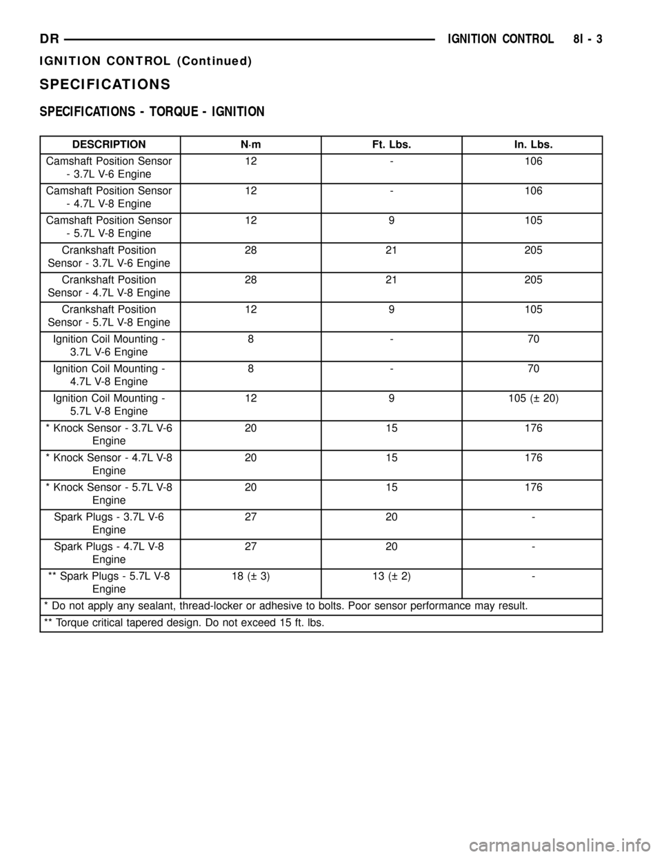
SPECIFICATIONS
SPECIFICATIONS - TORQUE - IGNITION
DESCRIPTION N´m Ft. Lbs. In. Lbs.
Camshaft Position Sensor
- 3.7L V-6 Engine12 - 106
Camshaft Position Sensor
- 4.7L V-8 Engine12 - 106
Camshaft Position Sensor
- 5.7L V-8 Engine12 9 105
Crankshaft Position
Sensor - 3.7L V-6 Engine28 21 205
Crankshaft Position
Sensor - 4.7L V-8 Engine28 21 205
Crankshaft Position
Sensor - 5.7L V-8 Engine12 9 105
Ignition Coil Mounting -
3.7L V-6 Engine8-70
Ignition Coil Mounting -
4.7L V-8 Engine8-70
Ignition Coil Mounting -
5.7L V-8 Engine12 9 105 ( 20)
* Knock Sensor - 3.7L V-6
Engine20 15 176
* Knock Sensor - 4.7L V-8
Engine20 15 176
* Knock Sensor - 5.7L V-8
Engine20 15 176
Spark Plugs - 3.7L V-6
Engine27 20 -
Spark Plugs - 4.7L V-8
Engine27 20 -
** Spark Plugs - 5.7L V-8
Engine18 ( 3) 13 ( 2) -
* Do not apply any sealant, thread-locker or adhesive to bolts. Poor sensor performance may result.
** Torque critical tapered design. Do not exceed 15 ft. lbs.
DRIGNITION CONTROL 8I - 3
IGNITION CONTROL (Continued)
Page 497 of 2627
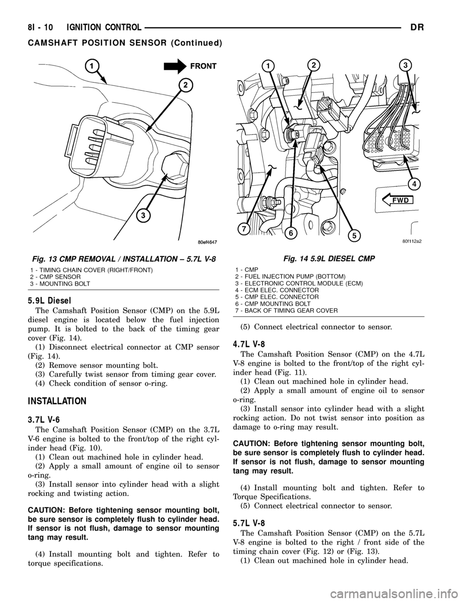
5.9L Diesel
The Camshaft Position Sensor (CMP) on the 5.9L
diesel engine is located below the fuel injection
pump. It is bolted to the back of the timing gear
cover (Fig. 14).
(1) Disconnect electrical connector at CMP sensor
(Fig. 14).
(2) Remove sensor mounting bolt.
(3) Carefully twist sensor from timing gear cover.
(4) Check condition of sensor o-ring.
INSTALLATION
3.7L V-6
The Camshaft Position Sensor (CMP) on the 3.7L
V-6 engine is bolted to the front/top of the right cyl-
inder head (Fig. 10).
(1) Clean out machined hole in cylinder head.
(2) Apply a small amount of engine oil to sensor
o-ring.
(3) Install sensor into cylinder head with a slight
rocking and twisting action.
CAUTION: Before tightening sensor mounting bolt,
be sure sensor is completely flush to cylinder head.
If sensor is not flush, damage to sensor mounting
tang may result.
(4) Install mounting bolt and tighten. Refer to
torque specifications.(5) Connect electrical connector to sensor.
4.7L V-8
The Camshaft Position Sensor (CMP) on the 4.7L
V-8 engine is bolted to the front/top of the right cyl-
inder head (Fig. 11).
(1) Clean out machined hole in cylinder head.
(2) Apply a small amount of engine oil to sensor
o-ring.
(3) Install sensor into cylinder head with a slight
rocking action. Do not twist sensor into position as
damage to o-ring may result.
CAUTION: Before tightening sensor mounting bolt,
be sure sensor is completely flush to cylinder head.
If sensor is not flush, damage to sensor mounting
tang may result.
(4) Install mounting bolt and tighten. Refer to
Torque Specifications.
(5) Connect electrical connector to sensor.
5.7L V-8
The Camshaft Position Sensor (CMP) on the 5.7L
V-8 engine is bolted to the right / front side of the
timing chain cover (Fig. 12) or (Fig. 13).
(1) Clean out machined hole in cylinder head.
Fig. 13 CMP REMOVAL / INSTALLATION ± 5.7L V-8
1 - TIMING CHAIN COVER (RIGHT/FRONT)
2 - CMP SENSOR
3 - MOUNTING BOLT
Fig. 14 5.9L DIESEL CMP
1 - CMP
2 - FUEL INJECTION PUMP (BOTTOM)
3 - ELECTRONIC CONTROL MODULE (ECM)
4 - ECM ELEC. CONNECTOR
5 - CMP ELEC. CONNECTOR
6 - CMP MOUNTING BOLT
7 - BACK OF TIMING GEAR COVER
8I - 10 IGNITION CONTROLDR
CAMSHAFT POSITION SENSOR (Continued)
Page 498 of 2627
(2) Apply a small amount of engine oil to sensor
o-ring.
(3) Install sensor into cylinder head with a slight
rocking action. Do not twist sensor into position as
damage to o-ring may result.
CAUTION: Before tightening sensor mounting bolt,
be sure sensor is completely flush to timing chain
cover. If sensor is not flush, damage to sensor
mounting tang may result.
(4) Install mounting bolt and tighten. Refer to
Torque Specifications.
(5) Connect electrical connector to sensor.
5.9L Diesel
The CMP is located on the back of the timing gear
cover (Fig. 14).
(1) Clean out machined hole in back of timing gear
cover.
(2) Apply a small amount of engine oil to sensor
o-ring.
(3) Install sensor into timing gear cover with a
slight rocking action. Do not twist sensor into posi-
tion as damage to o-ring may result.
CAUTION: Before tightening sensor mounting bolt,
be sure sensor is completely flush to back of timing
chain cover. If sensor is not flush, damage to sen-
sor mounting tang may result.
(4) Install mounting bolt and tighten. Refer to
Torque Specifications.
(5) Connect electrical connector to sensor.
IGNITION COIL
DESCRIPTION
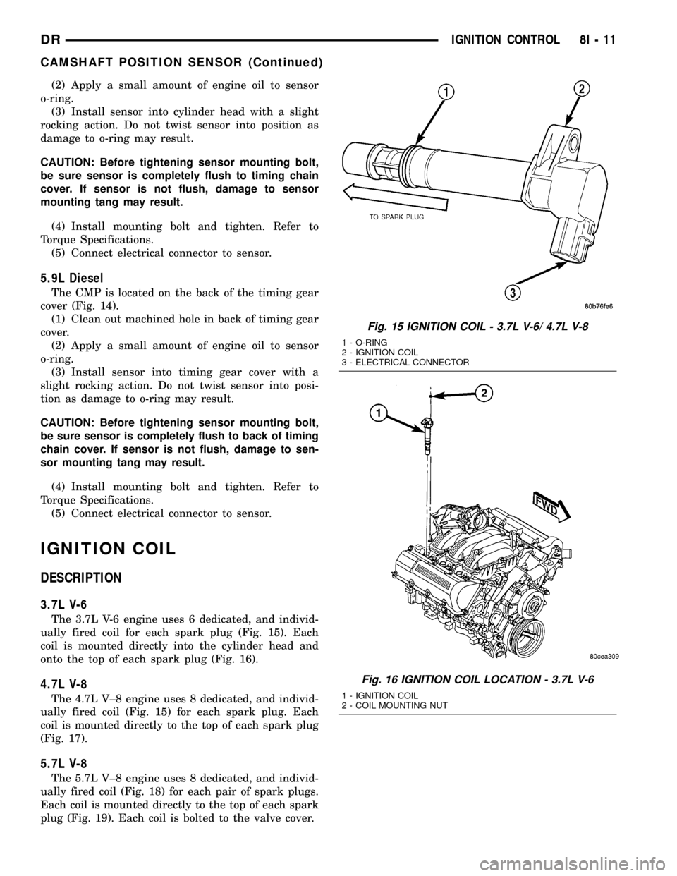
3.7L V-6
The 3.7L V-6 engine uses 6 dedicated, and individ-
ually fired coil for each spark plug (Fig. 15). Each
coil is mounted directly into the cylinder head and
onto the top of each spark plug (Fig. 16).
4.7L V-8
The 4.7L V±8 engine uses 8 dedicated, and individ-
ually fired coil (Fig. 15) for each spark plug. Each
coil is mounted directly to the top of each spark plug
(Fig. 17).
5.7L V-8
The 5.7L V±8 engine uses 8 dedicated, and individ-
ually fired coil (Fig. 18) for each pair of spark plugs.
Each coil is mounted directly to the top of each spark
plug (Fig. 19). Each coil is bolted to the valve cover.
Fig. 15 IGNITION COIL - 3.7L V-6/ 4.7L V-8
1 - O-RING
2 - IGNITION COIL
3 - ELECTRICAL CONNECTOR
Fig. 16 IGNITION COIL LOCATION - 3.7L V-6
1 - IGNITION COIL
2 - COIL MOUNTING NUT
DRIGNITION CONTROL 8I - 11
CAMSHAFT POSITION SENSOR (Continued)
Page 508 of 2627
(4) Install ignition coil(s). Refer to Ignition Coil
Removal/Installation.
5.7L V-8
(1) Special care should be taken when installing
spark plugs into the cylinder head spark plug wells.
Be sure the plugs do not drop into the plug wells as
electrodes can be damaged.
(2) Start the spark plug into cylinder head by
hand to avoid cross threading aluminum threads. To
aid in installation, attach a piece of rubber hose, or
an old spark plug boot to spark plug.
(3) The 5.7L V-8 is equipped with torque critical
design spark plugs. Do not exceed 15 ft. lbs. torque.
Tighten spark plugs. Refer to torque specifications.
(4) Before installing spark plug cables to either the
spark plugs or coils, apply dielectric grease to inside
of boots.
(5) To prevent ignition crossfire, spark plug cables
MUSTbe placed in cable tray (routing loom) into
their original position. Refer to Spark Plug Cable
Removal for a graphic.
(6) Install ignition coil(s) to necessary spark plugs.
Refer to Ignition Coil Installation.
(7) Install spark plug cables to remaining spark
plugs. Remember to apply dielectric grease to inside
of boots.
IGNITION COIL CAPACITOR
DESCRIPTION
One coil capacitor is used. It is located in the right-
rear section of the engine compartment.
OPERATION
The coil capacitor(s) help dampen the amount of
conducted electrical noise to the camshaft position
sensor, crankshaft position sensor, and throttle posi-
tion sensor. This noise is generated on the 12V sup-
ply wire to the ignition coils and fuel injectors.
REMOVAL
The coil capacitor is located in the right-rear sec-
tion of the engine compartment. It is attached with a
mounting stud and nut.
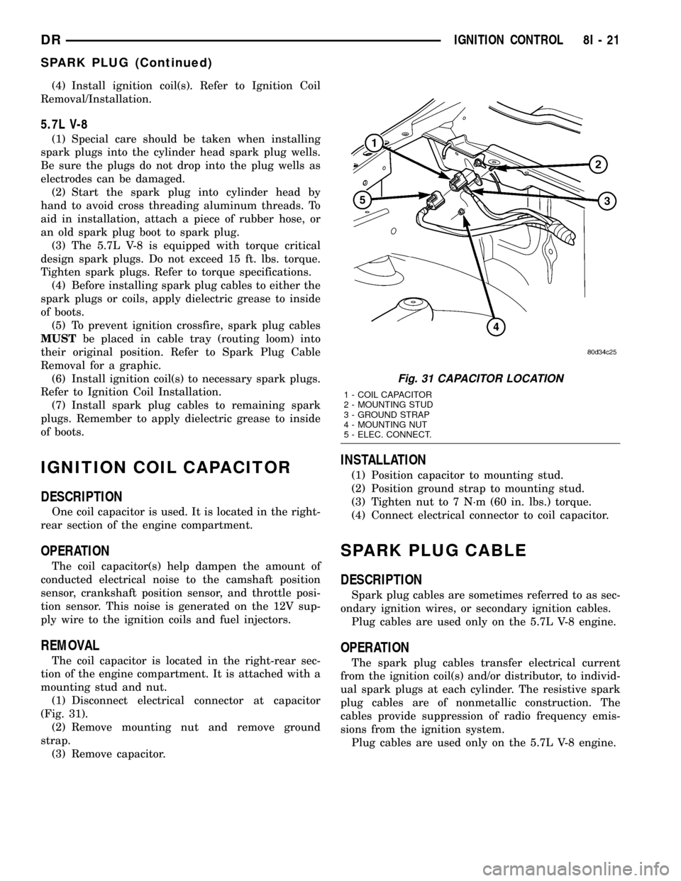
(1) Disconnect electrical connector at capacitor
(Fig. 31).
(2) Remove mounting nut and remove ground
strap.
(3) Remove capacitor.
INSTALLATION
(1) Position capacitor to mounting stud.
(2) Position ground strap to mounting stud.
(3) Tighten nut to 7 N´m (60 in. lbs.) torque.
(4) Connect electrical connector to coil capacitor.
SPARK PLUG CABLE
DESCRIPTION
Spark plug cables are sometimes referred to as sec-
ondary ignition wires, or secondary ignition cables.
Plug cables are used only on the 5.7L V-8 engine.
OPERATION
The spark plug cables transfer electrical current
from the ignition coil(s) and/or distributor, to individ-
ual spark plugs at each cylinder. The resistive spark
plug cables are of nonmetallic construction. The
cables provide suppression of radio frequency emis-
sions from the ignition system.
Plug cables are used only on the 5.7L V-8 engine.
Fig. 31 CAPACITOR LOCATION
1 - COIL CAPACITOR
2 - MOUNTING STUD
3 - GROUND STRAP
4 - MOUNTING NUT
5 - ELEC. CONNECT.
DRIGNITION CONTROL 8I - 21
SPARK PLUG (Continued)
Page 1224 of 2627
ENGINE
TABLE OF CONTENTS
page page
ENGINE - 3.7L............................ 1
ENGINE - 4.7L........................... 88ENGINE - 5.7L.......................... 180
ENGINE 5.9L DIESEL..................... 230
ENGINE - 3.7L
TABLE OF CONTENTS
page page
ENGINE - 3.7L
DESCRIPTION..........................3
DIAGNOSIS AND TESTING
DIAGNOSIS AND TESTING - ENGINE
DIAGNOSIS - INTRODUCTION............4
DIAGNOSIS AND TESTING - ENGINE
DIAGNOSIS - PERFORMANCE............4
DIAGNOSIS AND TESTING - ENGINE
DIAGNOSIS - MECHANICAL..............6
DIAGNOSIS AND TESTING - ENGINE
DIAGNOSIS - LUBRICATION..............7
DIAGNOSIS AND TESTING - CYLINDER
COMPRESSION PRESSURE..............8
DIAGNOSIS AND TESTING - CYLINDER
COMBUSTION PRESSURE LEAKAGE.......8
STANDARD PROCEDURE
STANDARD PROCEDURE - REPAIR
DAMAGED OR WORN THREADS..........9
STANDARD PROCEDURE - FORM-IN-
PLACE GASKETS AND SEALERS..........9
STANDARD PROCEDURE - ENGINE
GASKET SURFACE PREPARATION........10
REMOVAL.............................10
INSTALLATION.........................11
SPECIFICATIONS
SPECIFICATIONS - 3.7L ENGINE.........12
TORQUE............................16
SPECIAL TOOLS.......................17
AIR CLEANER ELEMENT
REMOVAL.............................21
INSTALLATION.........................21
CYLINDER HEAD - LEFT
DIAGNOSIS AND TESTING - CYLINDER HEAD
GASKET............................21
REMOVAL.............................22
INSTALLATION.........................24
CAMSHAFT(S)
DESCRIPTION.........................25
REMOVAL.............................25INSTALLATION.........................27
CYLINDER HEAD COVER(S)
DESCRIPTION.........................27
REMOVAL.............................28
INSTALLATION.........................28
INTAKE/EXHAUST VALVES & SEATS
DESCRIPTION.........................28
STANDARD PROCEDURE - REFACING......28
REMOVAL.............................29
INSTALLATION.........................30
ROCKER ARM
DESCRIPTION.........................31
REMOVAL.............................31
INSTALLATION.........................31
VALVE GUIDE SEALS
DESCRIPTION.........................32
VALVE SPRINGS
DESCRIPTION.........................32
REMOVAL.............................32
INSTALLATION.........................32
CYLINDER HEAD - RIGHT
DIAGNOSIS AND TESTING - HYDRAULIC
LASH ADJUSTER.....................32
REMOVAL.............................33
INSTALLATION.........................34
CAMSHAFT(S)
DESCRIPTION.........................35
REMOVAL.............................35
INSTALLATION.........................36
CYLINDER HEAD COVER(S)
REMOVAL.............................37
INSTALLATION.........................37
ROCKER ARM
DESCRIPTION.........................37
REMOVAL.............................37
VALVE GUIDE SEALS
DESCRIPTION.........................38
VALVE SPRINGS
DESCRIPTION.........................38
DRENGINE 9 - 1
Page 1235 of 2627
(17) Connect the engine to body ground straps at
the left side of the cowl.
(18) Install the intake manifold.
(19) Install the engine oil dipstick tube.
(20) Install the power brake booster vacuum hose.
(21) Install the breather hoses.
(22) Install the PCV hose.
(23) Install the fuel rail.
(24) Install the coil over plugs.
(25) Connect the engine wiring harness at the fol-
lowing points:
²Intake air temperature (IAT) sensor
²Fuel Injectors
²Throttle Position (TPS) Switch
²Idle Air Control (IAC) Motor
²Engine Oil Pressure Switch
²Engine Coolant Temperature (ECT) Sensor
²Manifold Absolute Pressure MAP) Sensor
²Camshaft Position (CMP) Sensor
²Coil Over Plugs
²Crankshaft Position Sensor
(26) Reinstall the radiator/cooling module assem-
bly.
(27) Connect lower radiator hose.
(28) Connect upper radiator hose.
(29) Connect throttle and speed control cables.
(30) Install the heater hose assembly.
(31) Install coolant recovery bottle.
(32) Install the power steering pump.
(33) Install the generator.
(34) Install the A/C compressor.
(35) Install the drive belt.
(36) Install the fan shroud with the viscous fan
assembly.
(37) Install the radiator core support bracket.
(38) Install the air cleaner assembly.
(39) Refill the engine cooling system.
(40) Recharge the air conditioning.
(41) Install the hood.
(42) Check and fill engine oil.
(43) Connect the battery negative cable.
(44) Start the engine and check for leaks.SPECIFICATIONS
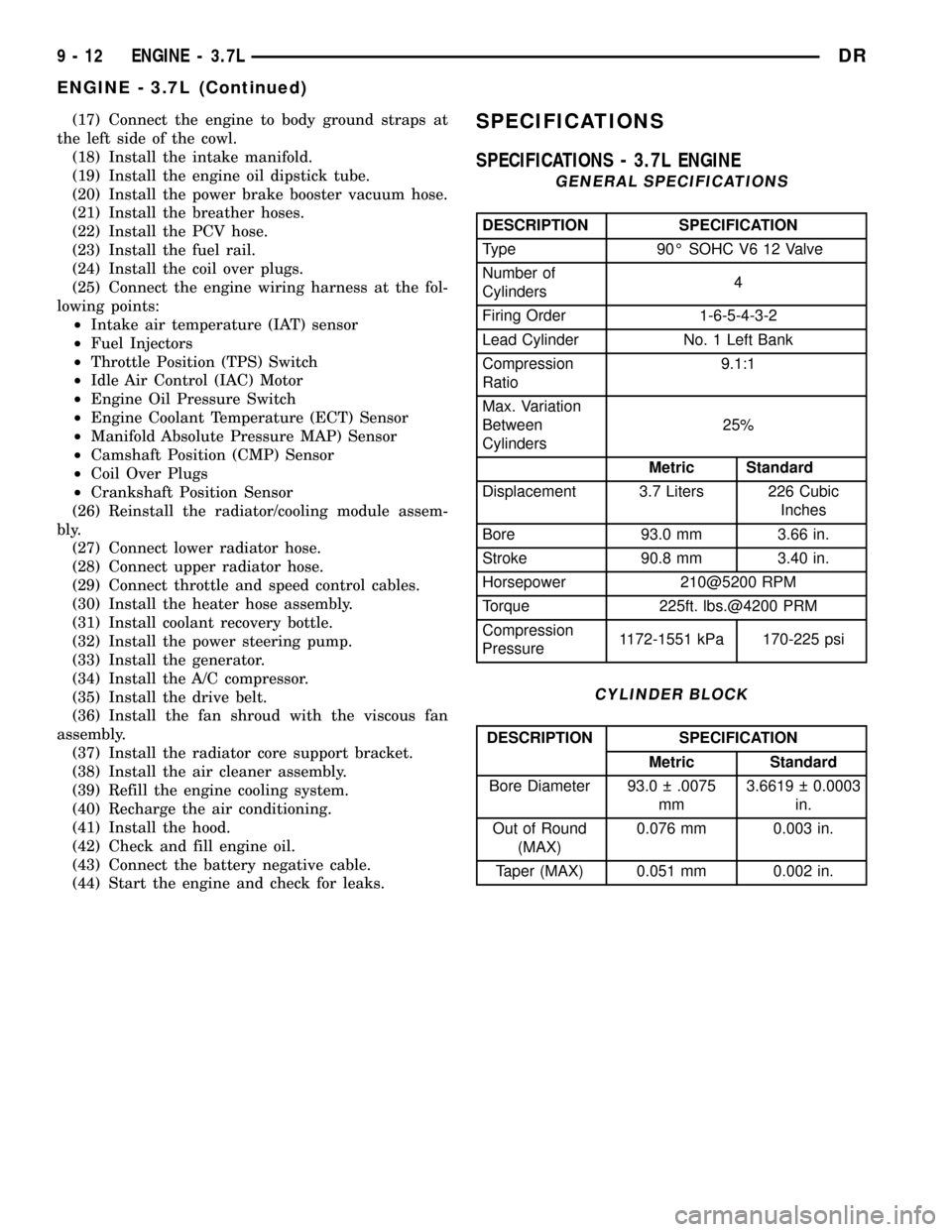
SPECIFICATIONS - 3.7L ENGINE
GENERAL SPECIFICATIONS
DESCRIPTION SPECIFICATION
Type 90É SOHC V6 12 Valve
Number of
Cylinders4
Firing Order 1-6-5-4-3-2
Lead Cylinder No. 1 Left Bank
Compression
Ratio9.1:1
Max. Variation
Between
Cylinders25%
Metric Standard
Displacement 3.7 Liters 226 Cubic
Inches
Bore 93.0 mm 3.66 in.
Stroke 90.8 mm 3.40 in.
Horsepower 210@5200 RPM
Torque 225ft. lbs.@4200 PRM
Compression
Pressure1172-1551 kPa 170-225 psi
CYLINDER BLOCK
DESCRIPTION SPECIFICATION
Metric Standard
Bore Diameter 93.0 .0075
mm3.6619 0.0003
in.
Out of Round
(MAX)0.076 mm 0.003 in.
Taper (MAX) 0.051 mm 0.002 in.
9 - 12 ENGINE - 3.7LDR
ENGINE - 3.7L (Continued)
Page 1237 of 2627
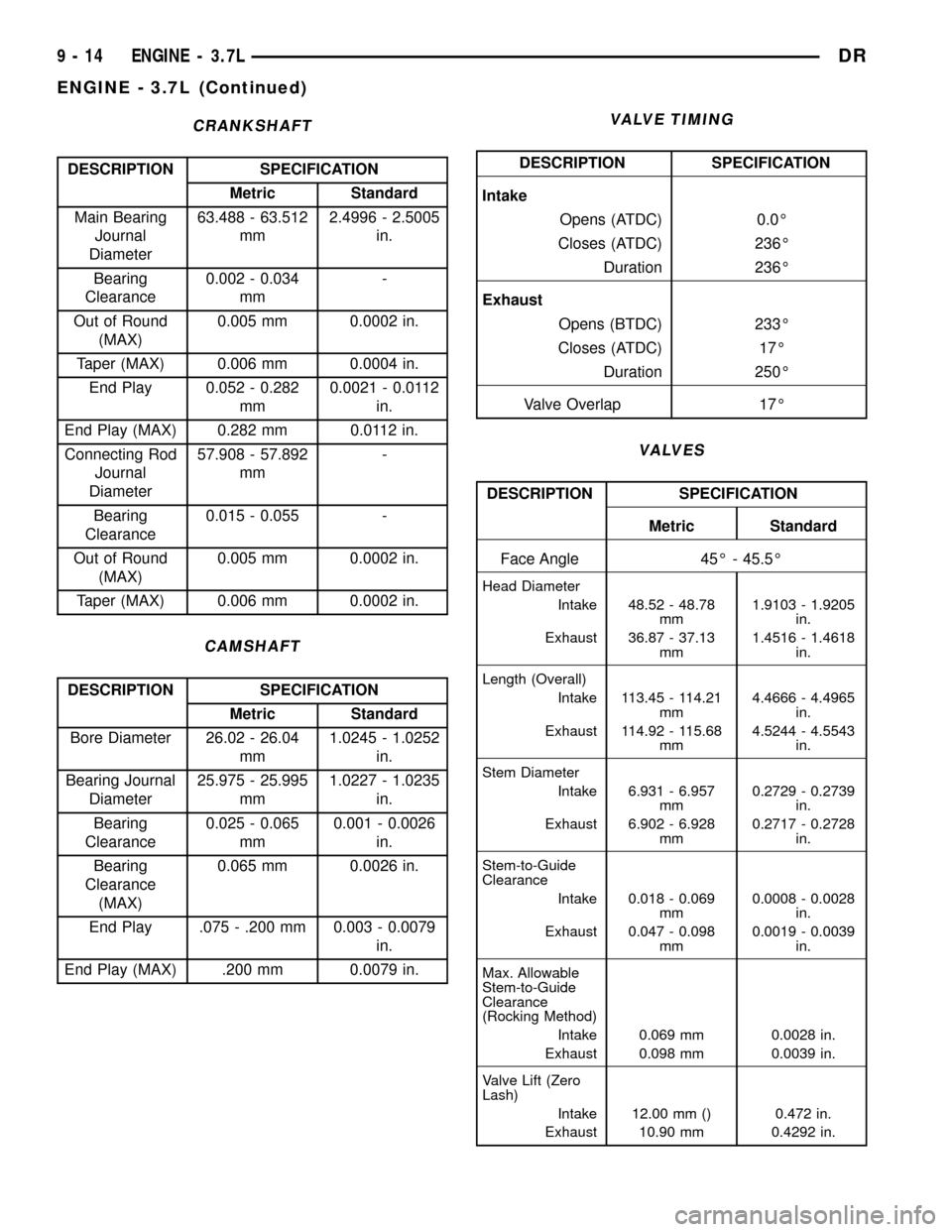
CRANKSHAFT
DESCRIPTION SPECIFICATION
Metric Standard
Main Bearing
Journal
Diameter63.488 - 63.512
mm2.4996 - 2.5005
in.
Bearing
Clearance0.002 - 0.034
mm-
Out of Round
(MAX)0.005 mm 0.0002 in.
Taper (MAX) 0.006 mm 0.0004 in.
End Play 0.052 - 0.282
mm0.0021 - 0.0112
in.
End Play (MAX) 0.282 mm 0.0112 in.
Connecting Rod
Journal
Diameter57.908 - 57.892
mm-
Bearing
Clearance0.015 - 0.055 -
Out of Round
(MAX)0.005 mm 0.0002 in.
Taper (MAX) 0.006 mm 0.0002 in.
CAMSHAFT
DESCRIPTION SPECIFICATION
Metric Standard
Bore Diameter 26.02 - 26.04
mm1.0245 - 1.0252
in.
Bearing Journal
Diameter25.975 - 25.995
mm1.0227 - 1.0235
in.
Bearing
Clearance0.025 - 0.065
mm0.001 - 0.0026
in.
Bearing
Clearance
(MAX)0.065 mm 0.0026 in.
End Play .075 - .200 mm 0.003 - 0.0079
in.
End Play (MAX) .200 mm 0.0079 in.
VALVE TIMING
DESCRIPTION SPECIFICATION
Intake
Opens (ATDC) 0.0É
Closes (ATDC) 236É
Duration 236É
Exhaust
Opens (BTDC) 233É
Closes (ATDC) 17É
Duration 250É
Valve Overlap 17É
VALVES
DESCRIPTION SPECIFICATION
Metric Standard
Face Angle 45É - 45.5É
Head Diameter
Intake 48.52 - 48.78
mm1.9103 - 1.9205
in.
Exhaust 36.87 - 37.13
mm1.4516 - 1.4618
in.
Length (Overall)
Intake 113.45 - 114.21
mm4.4666 - 4.4965
in.
Exhaust 114.92 - 115.68
mm4.5244 - 4.5543
in.
Stem Diameter
Intake 6.931 - 6.957
mm0.2729 - 0.2739
in.
Exhaust 6.902 - 6.928
mm0.2717 - 0.2728
in.
Stem-to-Guide
Clearance
Intake 0.018 - 0.069
mm0.0008 - 0.0028
in.
Exhaust 0.047 - 0.098
mm0.0019 - 0.0039
in.
Max. Allowable
Stem-to-Guide
Clearance
(Rocking Method)
Intake 0.069 mm 0.0028 in.
Exhaust 0.098 mm 0.0039 in.
Valve Lift (Zero
Lash)
Intake 12.00 mm () 0.472 in.
Exhaust 10.90 mm 0.4292 in.
9 - 14 ENGINE - 3.7LDR
ENGINE - 3.7L (Continued)
Page 1239 of 2627
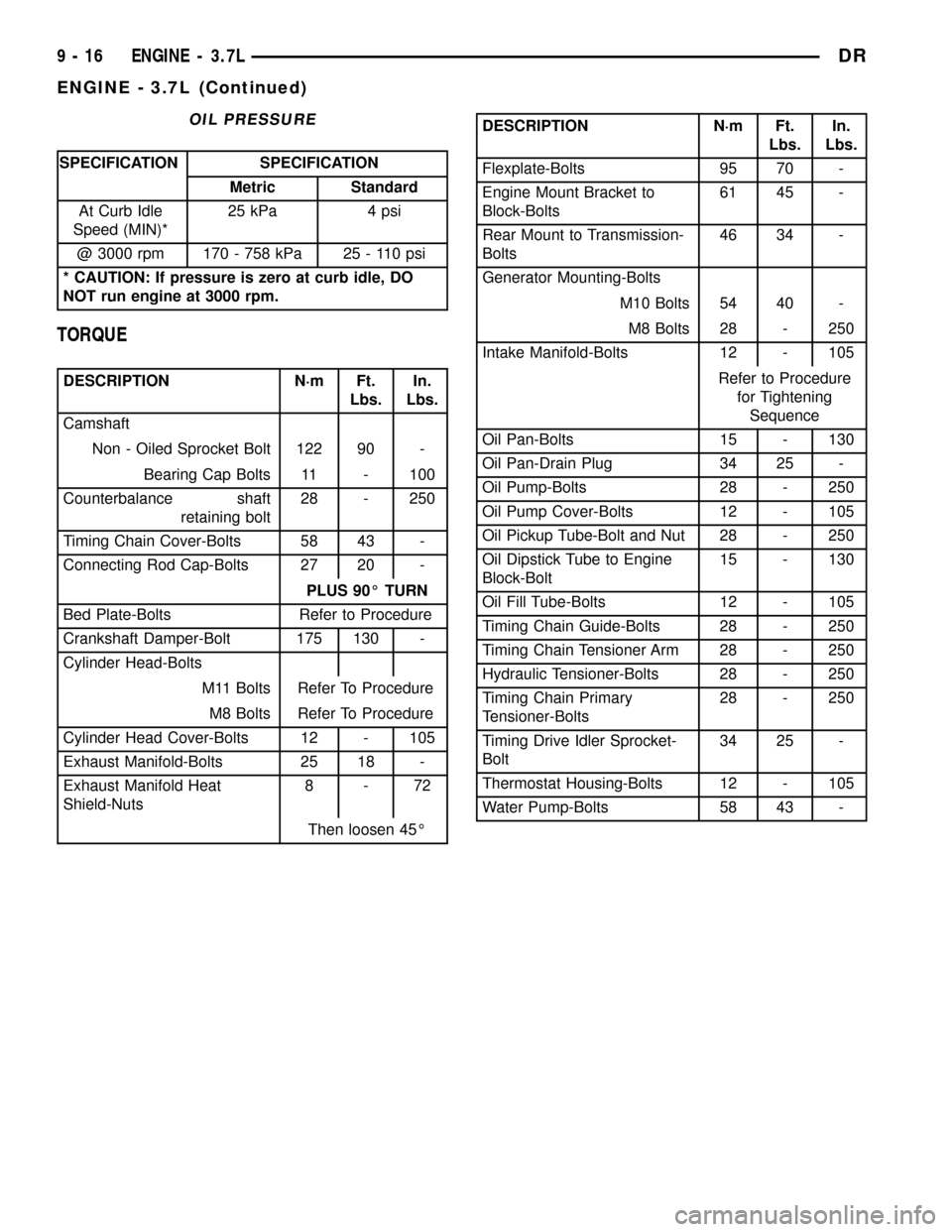
OIL PRESSURE
SPECIFICATION SPECIFICATION
Metric Standard
At Curb Idle
Speed (MIN)*25 kPa 4 psi
@ 3000 rpm 170 - 758 kPa 25 - 110 psi
* CAUTION: If pressure is zero at curb idle, DO
NOT run engine at 3000 rpm.
TORQUE
DESCRIPTION N´m Ft.
Lbs.In.
Lbs.
Camshaft
Non - Oiled Sprocket Bolt 122 90 -
Bearing Cap Bolts 11 - 100
Counterbalance shaft
retaining bolt28 - 250
Timing Chain Cover-Bolts 58 43 -
Connecting Rod Cap-Bolts 27 20 -
PLUS 90É TURN
Bed Plate-Bolts Refer to Procedure
Crankshaft Damper-Bolt 175 130 -
Cylinder Head-Bolts
M11 Bolts Refer To Procedure
M8 Bolts Refer To Procedure
Cylinder Head Cover-Bolts 12 - 105
Exhaust Manifold-Bolts 25 18 -
Exhaust Manifold Heat
Shield-Nuts8-72
Then loosen 45É
DESCRIPTION N´m Ft.
Lbs.In.
Lbs.
Flexplate-Bolts 95 70 -
Engine Mount Bracket to
Block-Bolts61 45 -
Rear Mount to Transmission-
Bolts46 34 -
Generator Mounting-Bolts
M10 Bolts 54 40 -
M8 Bolts 28 - 250
Intake Manifold-Bolts 12 - 105
Refer to Procedure
for Tightening
Sequence
Oil Pan-Bolts 15 - 130
Oil Pan-Drain Plug 34 25 -
Oil Pump-Bolts 28 - 250
Oil Pump Cover-Bolts 12 - 105
Oil Pickup Tube-Bolt and Nut 28 - 250
Oil Dipstick Tube to Engine
Block-Bolt15 - 130
Oil Fill Tube-Bolts 12 - 105
Timing Chain Guide-Bolts 28 - 250
Timing Chain Tensioner Arm 28 - 250
Hydraulic Tensioner-Bolts 28 - 250
Timing Chain Primary
Tensioner-Bolts28 - 250
Timing Drive Idler Sprocket-
Bolt34 25 -
Thermostat Housing-Bolts 12 - 105
Water Pump-Bolts 58 43 -
9 - 16 ENGINE - 3.7LDR
ENGINE - 3.7L (Continued)
Page 1253 of 2627
TESTING VALVE SPRINGS
NOTE: Whenever the valves are removed from the
cylinder head it is recommended that the valve
springs be inspected and tested for reuse.
Inspect the valve springs for physical signs of wear or
damage. Turn table of tool C-647 until surface is in line
with the 40.12 mm (1.579 in.) mark on the threaded
stud and the zero mark on the front. Place spring over
the stud on the table and lift compressing lever to set
tone device. Pull on torque wrench until a Ping is
heard. Take reading on torque wrench at this instant.
Multiply this reading by two. This will give the spring
load at test length. Fractional measurements are indi-
cated on the table for finer adjustments. Refer to Spec-
ifications Section to obtain specified height and
allowable tensions. Replace any springs that do not
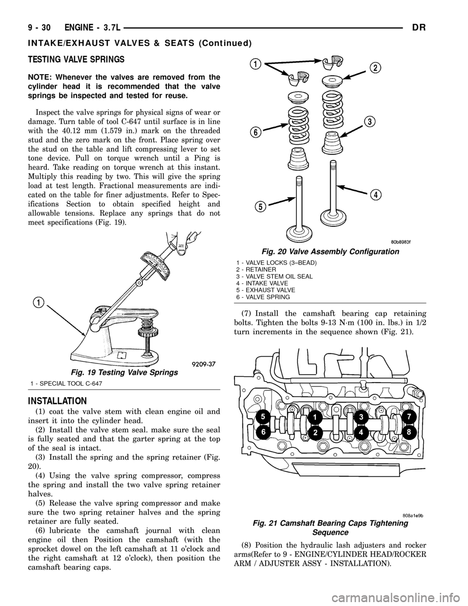
meet specifications (Fig. 19).
INSTALLATION
(1) coat the valve stem with clean engine oil and
insert it into the cylinder head.
(2) Install the valve stem seal. make sure the seal
is fully seated and that the garter spring at the top
of the seal is intact.
(3) Install the spring and the spring retainer (Fig.
20).
(4) Using the valve spring compressor, compress
the spring and install the two valve spring retainer
halves.
(5) Release the valve spring compressor and make
sure the two spring retainer halves and the spring
retainer are fully seated.
(6) lubricate the camshaft journal with clean
engine oil then Position the camshaft (with the
sprocket dowel on the left camshaft at 11 o'clock and
the right camshaft at 12 o'clock), then position the
camshaft bearing caps.(7) Install the camshaft bearing cap retaining
bolts. Tighten the bolts 9-13 N´m (100 in. lbs.) in 1/2
turn increments in the sequence shown (Fig. 21).
(8)
Position the hydraulic lash adjusters and rocker
arms(Refer to 9 - ENGINE/CYLINDER HEAD/ROCKER
ARM / ADJUSTER ASSY - INSTALLATION).
Fig. 19 Testing Valve Springs
1 - SPECIAL TOOL C-647
Fig. 20 Valve Assembly Configuration
1 - VALVE LOCKS (3±BEAD)
2 - RETAINER
3 - VALVE STEM OIL SEAL
4 - INTAKE VALVE
5 - EXHAUST VALVE
6 - VALVE SPRING
Fig. 21 Camshaft Bearing Caps Tightening
Sequence
9 - 30 ENGINE - 3.7LDR
INTAKE/EXHAUST VALVES & SEATS (Continued)