Capacity DODGE RAM 1500 1998 2.G Workshop Manual
[x] Cancel search | Manufacturer: DODGE, Model Year: 1998, Model line: RAM 1500, Model: DODGE RAM 1500 1998 2.GPages: 2627
Page 18 of 2627
FLUID ADDITIVES
DaimlerChrysler strongly recommends against the
addition of any fluids to the transmission, other than
those automatic transmission fluids listed above.
Exceptions to this policy are the use of special dyes
to aid in detecting fluid leaks.
Various ªspecialº additives and supplements exist
that claim to improve shift feel and/or quality. These
additives and others also claim to improve converter
clutch operation and inhibit overheating, oxidation,
varnish, and sludge. These claims have not been sup-
ported to the satisfaction of DaimlerChrysler and
these additivesmust not be used.The use of trans-
mission ªsealersº should also be avoided, since they
may adversely affect the integrity of transmission
seals.
OPERATION - AUTOMATIC TRANSMISSION
FLUID
The automatic transmission fluid is selected based
upon several qualities. The fluid must provide a high
level of protection for the internal components by
providing a lubricating film between adjacent metal
components. The fluid must also be thermally stable
so that it can maintain a consistent viscosity through
a large temperature range. If the viscosity stays con-
stant through the temperature range of operation,
transmission operation and shift feel will remain con-
sistent. Transmission fluid must also be a good con-
ductor of heat. The fluid must absorb heat from the
internal transmission components and transfer that
heat to the transmission case.
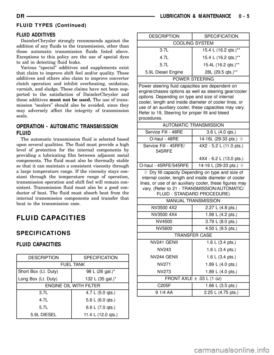
FLUID CAPACITIES
SPECIFICATIONS
FLUID CAPACITIES
DESCRIPTION SPECIFICATION
FUEL TANK
Short Box (Lt. Duty) 98 L (26 gal.)*
Long Box (Lt. Duty) 132 L (35 gal.)*
ENGINE OIL WITH FILTER
3.7L 4.7 L (5.0 qts.)
4.7L 5.6 L (6.0 qts.)
5.7L 6.6 L (7.0 qts.)
5.9L DIESEL 11.4 L (12.0 qts.)
DESCRIPTION SPECIFICATION
COOLING SYSTEM
3.7L 15.4 L (16.2 qts.)**
4.7L 15.4 L (16.2 qts.)**
5.7L 15.4L (16.2 qts.)**
5.9L Diesel Engine 28L (29.5 qts.)**
POWER STEERING
Power steering fluid capacities are dependent on
engine/chassis options as well as steering gear/cooler
options. Depending on type and size of internal
cooler, length and inside diameter of cooler lines, or
use of an auxiliary cooler, these capacities may vary.
Refer to 19, Steering for proper fill and bleed
procedures.
AUTOMATIC TRANSMISSION
Service Fill - 48RE 3.8 L (4.0 qts.)
O-haul - 48RE 14-16L (29-33 pts.)L
Service Fill - 45RFE/
545RFE4X2 - 5.2 L (11.0 pts.)
4X4 - 6.2 L (13.0 pts.)
O-haul - 45RFE/545RFE 14-16 L (29-33 pts.)L
LDry fill capacity Depending on type and size of
internal cooler, length and inside diameter of cooler
lines, or use of an auxiliary cooler, these figures may
vary. (Refer to 21 - TRANSMISSION/AUTOMATIC/
FLUID - STANDARD PROCEDURE)
MANUAL TRANSMISSION
NV3500 4X2 2.27 L (4.8 pts.)
NV3500 4X4 1.99 L (4.2 pts.)
NV4500 3.79 L (8.0 pts.)
NV5600 4.50 L (9.5 pts.)
TRANSFER CASE
NV241 GENII 1.6 L (3.4 pts.)
NV243 1.6 L (3.4 pts.)
NV244 GENII 1.6 L (3.4 pts.)
NV271 1.89 L (4.0 pts.)
NV273 1.89 L (4.0 pts.)
FRONT AXLE .03 L (1 oz)
C205F 1.66 L (3.5 pts.)
9 1/4 AA 2.25 L (4.75 pts.)
DRLUBRICATION & MAINTENANCE 0 - 5
FLUID TYPES (Continued)
Page 156 of 2627
(20) Fill differential with lubricant, refer to Lubri-
cation & Maintenance for capacity and lubricant
type.
(21) Install fill plug and tighten to 32 N´m (24 ft.
lbs.).
DIFFERENTIAL CASE
BEARINGS
REMOVAL
(1) Remove the differential case from the housing.
(2) Install Plug 8888 into the end of the case.
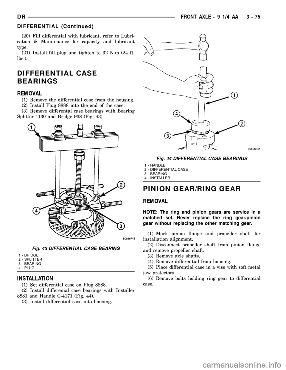
(3) Remove differental case bearings with Bearing
Splitter 1130 and Bridge 938 (Fig. 43).
INSTALLATION
(1) Set differential case on Plug 8888.
(2) Install differenial case bearings with Installer
8881 and Handle C-4171 (Fig. 44).
(3) Install differentail case into housing.
PINION GEAR/RING GEAR
REMOVAL
NOTE: The ring and pinion gears are service in a
matched set. Never replace the ring gear/pinion
gear without replacing the other matching gear.
(1) Mark pinion flange and propeller shaft for
installation alignment.
(2) Disconnect propeller shaft from pinion flange
and remove propeller shaft.
(3) Remove axle shafts.
(4) Remove differential from housing.
(5) Place differential case in a vise with soft metal
jaw protectors
(6) Remove bolts holding ring gear to differential
case.
Fig. 43 DIFFERENTIAL CASE BEARING
1 - BRIDGE
2 - SPLITTER
3 - BEARING
4 - PLUG
Fig. 44 DIFFERENTIAL CASE BEARINGS
1 - HANDLE
2 - DIFFERENTIAL CASE
3 - BEARING
4 - INSTALLER
DRFRONT AXLE - 9 1/4 AA 3 - 75
DIFFERENTIAL (Continued)
Page 211 of 2627

INSTALLATION
(1) Clean the housing cavity with a flushing oil,
light engine oil or lint free cloth.
CAUTION: Do not use water, steam, kerosene or
gasoline for cleaning.
(2) Lubricate differential case bearing.
(3) Install differential case with bearings cups into
the housing.
NOTE: A light coat of grease on the cups will hold
them in place during installation.
(4) Install bearing caps and bolts (Fig. 36). Tighten
the bearing cap bolts finger-tight.
NOTE: Do not torque bearing cap and bolts at this
time.
(5) Slide differential case toward the pinion gear
until the gears make contact/zero backlash. If zero
backlash cannot be obtained, turn the pinion side
adjuster until zero backlash is obtained.
(6) Holding the differential case toward the pinion
gear, turn bearing adjusters with Spanner Wrench
8883 until they make contact with the differential
bearings/cups.
(7) Back off the ring gear side adjuster 4 holes, to
obtain initial ring gear backlash.
(8) Install ring gear side adjuster lock and bolt. Do
not tighten adjuster lock bolt at this time.(9) Tighten pinion gear side adjuster firmly
against the differential case bearing cup.
(10) Rotate the pinion several times to seat the dif-
ferential bearings.
(11) Loosen pinion gear side adjuster until it is no
longer in contact with the bearing cup.
(12) Tighten pinion gear side adjuster until it just
makes contact with the bearing cup.
(13) Tighten pinion gear side adjuster an addi-
tional:
²New Bearings6 Adjuster Holes
²Original Bearings4 Adjuster Holes
(14) Install pinion gear side adjuster lock and bolt.
Do not tighten adjuster lock bolt at this time.
(15) Tighten bearing cap bolts to 165 N´m (122 ft.
lbs.).
(16) Tighten adjuster lock bolts to 25 N´m (18 ft.
lbs.) (Fig. 37).
(17) Measure ring gear backlash and check gear
tooth contact pattern. Refer to Adjustments for pro-
cedure.
(18) Install axle shafts.
(19) Install differential housing gasket and cover.
Tighten cover bolts to 40 N´m (30 ft. lbs.).
(20) Fill axle with lubricant, refer to Lubrication &
Maintenance for capacity and lubricant type.
(21) Install fill plug and tighten to 32 N´m (24 ft.
lbs.).
Fig. 36 CASE BEARING CAP
1 - DIFFERENTIAL HOUSING
2 - BEARING CAP
3 - ADJUSTERFig. 37 ADJUSTER LOCK BOLT
1 - DIFFERENTIAL CASE
2 - ADJUSTER LOCK
3 - ADJUSTER LOCK BOLT
4 - BEARING CAP BOLT
3 - 130 REAR AXLE - 10 1/2 AADR
DIFFERENTIAL (Continued)
Page 239 of 2627
(5) Slide differential case toward the pinion gear
until the gears make contact/zero backlash. If zero
backlash cannot be obtained, turn the pinion side
adjuster until zero backlash is obtained.
(6) Holding the differential case toward the pinion
gear, turn bearing adjusters with Spanner Wrench
8883 until they make contact with the differential
bearings/cups.
(7) Back off the ring gear side adjuster 4 holes, to
obtain initial ring gear backlash.
(8) Install ring gear side adjuster lock and bolt. Do
not tighten adjuster lock bolt at this time.
(9) Tighten pinion gear side adjuster firmly
against the differential case bearing cup.
(10) Rotate the pinion several times to seat the dif-
ferential bearings.
(11) Loosen pinion gear side adjuster until it is no
longer in contact with the bearing cup.
(12) Tighten pinion gear side adjuster until it just
makes contact with the bearing cup.
(13) Tighten pinion gear side adjuster an addi-
tional:
²New Bearings6 Adjuster Holes
²Original Bearings4 Adjuster Holes
(14) Install pinion gear side adjuster lock and bolt.
Do not tighten adjuster lock bolt at this time.
(15) Tighten bearing cap bolts to 281 N´m (207 ft.
lbs.).
(16) Tighten adjuster lock bolts to 25 N´m (18 ft.
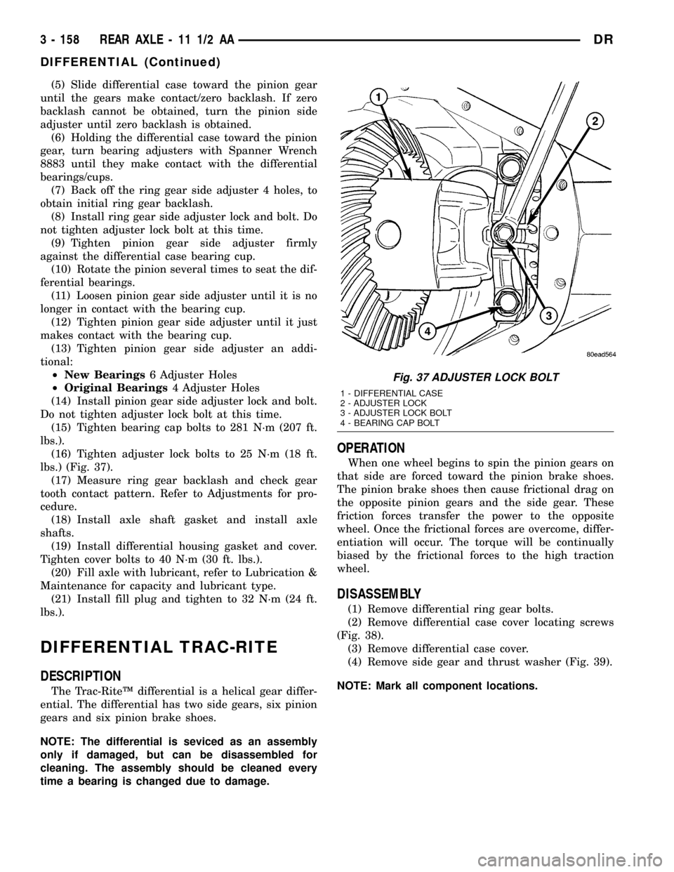
lbs.) (Fig. 37).
(17) Measure ring gear backlash and check gear
tooth contact pattern. Refer to Adjustments for pro-
cedure.
(18) Install axle shaft gasket and install axle
shafts.
(19) Install differential housing gasket and cover.
Tighten cover bolts to 40 N´m (30 ft. lbs.).
(20) Fill axle with lubricant, refer to Lubrication &
Maintenance for capacity and lubricant type.
(21) Install fill plug and tighten to 32 N´m (24 ft.
lbs.).
DIFFERENTIAL TRAC-RITE
DESCRIPTION
The Trac-RiteŸ differential is a helical gear differ-
ential. The differential has two side gears, six pinion
gears and six pinion brake shoes.
NOTE: The differential is seviced as an assembly
only if damaged, but can be disassembled for
cleaning. The assembly should be cleaned every
time a bearing is changed due to damage.
OPERATION
When one wheel begins to spin the pinion gears on
that side are forced toward the pinion brake shoes.
The pinion brake shoes then cause frictional drag on
the opposite pinion gears and the side gear. These
friction forces transfer the power to the opposite
wheel. Once the frictional forces are overcome, differ-
entiation will occur. The torque will be continually
biased by the frictional forces to the high traction
wheel.
DISASSEMBLY
(1) Remove differential ring gear bolts.
(2) Remove differential case cover locating screws
(Fig. 38).
(3) Remove differential case cover.
(4) Remove side gear and thrust washer (Fig. 39).
NOTE: Mark all component locations.
Fig. 37 ADJUSTER LOCK BOLT
1 - DIFFERENTIAL CASE
2 - ADJUSTER LOCK
3 - ADJUSTER LOCK BOLT
4 - BEARING CAP BOLT
3 - 158 REAR AXLE - 11 1/2 AADR
DIFFERENTIAL (Continued)
Page 316 of 2627
COOLING
TABLE OF CONTENTS
page page
COOLING
DESCRIPTION
DESCRIPTION - COOLING SYSTEM FLOW
3.7L/4.7L/5.7L ENGINE..................1
DESCRIPTION - COOLING SYSTEM FLOW -
5.9L DIESEL..........................3
DESCRIPTION - HOSE CLAMPS...........3
OPERATION
OPERATION - COOLING SYSTEM.........5
OPERATION - HOSE CLAMPS............5
DIAGNOSIS AND TESTING
DIAGNOSIS AND TESTINGÐON-BOARD
DIAGNOSTICS (OBD)...................5
DIAGNOSIS AND TESTING - COOLING
SYSTEM - TESTING FOR LEAKS..........5
DIAGNOSIS AND TESTING - COOLING
SYSTEM DIESEL ENGINE................7
DIAGNOSIS AND TESTING - PRELIMINARY
CHECKS............................10
STANDARD PROCEDURE
STANDARD PROCEDURE - COOLANT
LEVEL CHECK........................17STANDARD PROCEDURE - COOLING
SYSTEM CLEANING/REVERSE FLUSHING . . 17
STANDARD PROCEDURE - DRAINING
COOLING SYSTEM - ALL GAS ENGINES . . . 17
STANDARD PROCEDURE - REFILLING
COOLING SYSTEM - ALL GAS ENGINES . . . 18
STANDARD PROCEDURE - DRAINING
COOLING SYSTEM 5.9L DIESEL ENGINE . . . 18
STANDARD PROCEDURE - REFILLING
COOLING SYSTEM 5.9L DIESEL ENGINE . . . 19
STANDARD PROCEDURE - ADDING
ADDITIONAL COOLANT.................19
SPECIFICATIONS
TORQUE............................19
SPECIFICATIONS -....................20
SPECIAL TOOLS
COOLING...........................20
ACCESSORY DRIVE......................21
ENGINE...............................30
TRANSMISSION.........................67
COOLING
DESCRIPTION
DESCRIPTION - COOLING SYSTEM FLOW
3.7L/4.7L/5.7L ENGINE
The cooling system regulates engine operating tem-
perature. It allows the engine to reach normal oper-
ating temperature as quickly as possible. It also
maintains normal operating temperature and pre-
vents overheating.The cooling system provides a means of heating
the passenger compartment and cooling the auto-
matic transmission fluid (if equipped). The cooling
system is pressurized and uses a centrifugal water
pump to circulate coolant through the system. The
coolant recovery/reserve system utilizes an ambient
overflow bottle (Fig. 2).
An optional factory installed maximum duty cool-
ing package is available on most models. This pack-
age will provide additional cooling capacity for
vehicles used under extreme conditions such as
trailer towing in high ambient temperatures (Fig. 1).
DRCOOLING 7 - 1
Page 320 of 2627

OPERATION
OPERATION - COOLING SYSTEM
The cooling system regulates engine operating tem-
perature. It allows the engine to reach normal oper-
ating temperature as quickly as possible. It also
maintains normal operating temperature and pre-
vents overheating.
The cooling system also provides a means of heat-
ing the passenger compartment and cooling the auto-
matic transmission fluid (if equipped). The cooling
system is pressurized and uses a centrifugal water
pump to circulate coolant throughout the system.
All engines utilize an ambient overflow bottle for
coolant recovery/reserve.
An optional factory installed maximum duty cool-
ing package is available on most models. This pack-
age will provide additional cooling capacity for
vehicles used under extreme conditions such as
trailer towing in high ambient temperatures.
OPERATION - HOSE CLAMPS
The spring type hose clamp applies constant ten-
sion on a hose connection. To remove a spring type
hose clamp, only use constant tension clamp pliers
designed to compress the hose clamp.
DIAGNOSIS AND TESTING
DIAGNOSIS AND TESTINGÐON-BOARD
DIAGNOSTICS (OBD)
COOLING SYSTEM RELATED DIAGNOSTICS
The Engine Control Module (ECM) has been pro-
grammed to monitor certain cooling system compo-
nents:
²If the engine has remained cool for too long a
period, such as with a stuck open thermostat, a Diag-
nostic Trouble Code (DTC) can be set.
²If an open or shorted condition has developed in
the electronically controlled viscous fan clutch circuit,
a Diagnostic Trouble Code (DTC) can be set.
²If fan speed is not detected a DTC will be set.
²Coolant temperature sensor circuit problems can
set a DTC.
If the problem is sensed in a monitored circuit
often enough to indicated an actual problem, a DTC
is stored. The DTC will be stored in the ECM mem-
ory for eventual display to the service technician.
(Refer to 25 - EMISSIONS CONTROL - DESCRIP-
TION).
ACCESSING DIAGNOSTIC TROUBLE CODES
To read DTC's and to obtain cooling system data,
(Refer to 25 - EMISSIONS CONTROL - DESCRIP-
TION).
ERASING TROUBLE CODES
After the problem has been repaired, use the
DRBIIItscan tool to erase a DTC. Refer to the
appropriate Powertrain Diagnostic Procedures ser-
vice information for operation of the DRBIIItscan
tool.
DIAGNOSIS AND TESTING - COOLING SYSTEM
- TESTING FOR LEAKS
ULTRAVIOLET LIGHT METHOD
A leak detection additive is available through the
parts department that can be added to cooling sys-
tem. The additive is highly visible under ultraviolet
light (black light). Pour one ounce of additive into
cooling system. Place heater control unit in HEAT
position. Start and operate the engine until the radi-
ator upper hose is warm to the touch. Aim the com-
mercially available black light tool at the components
to be checked. If leaks are present, the black light
will cause the additive to glow a bright green color.
The black light can be used in conjunction with a
pressure tester to determine if any external leaks
exist (Fig. 5).
Fig. 4 Spring Clamp Size Location
1 - SPRING CLAMP SIZE LOCATION
DRCOOLING 7 - 5
COOLING (Continued)
Page 362 of 2627

DIAGNOSIS AND TESTING - THERMOSTAT
The cooling system used with the diesel engine
provides the extra coolant capacity and extra cooling
protection needed for higher GVWR (Gross Vehicle
Weight Rating) and GCWR (Gross Combined Weight
Rating) vehicles.
This system capacity will not effect warm up or
cold weather operating characteristics if the thermo-
stat is operating properly. This is because coolant
will be held in the engine until it reaches the ther-
mostat ªsetº temperature.
Diesel engines, due to their inherent efficiency are
slower to warm up than gasoline powered engines,
and will operate at lower temperatures when the
vehicle is unloaded. Because of this, lower tempera-
ture gauge readings for diesel versus gasoline
engines may, at times be normal.
Typically, complaints of low engine coolant temper-
ature are observed as low heater output when com-
bined with cool or cold outside temperatures.
To help promote faster engine warm-up, the elec-
tric engine block heater must be used with cool or
cold outside temperatures. This will help keep the
engine coolant warm when the vehicle is parked.
A ªCold Weather Coverº is available from the parts
department through the Mopar Accessories product
line. This accessory cover is designed to block airflow
entering the radiator and engine compartment to
promote faster engine warm-up. It attaches to the
front of the vehicle at the grill opening.The cover is
to be used with cool or cold temperatures only.
If used with high outside temperatures, serious
engine damage could result.Refer to the litera-
ture supplied with the cover for additional informa-
tion.
(1) To determine if the thermostat is defective, it
must be removed from the vehicle (Refer to 7 -
COOLING/ENGINE/ENGINE COOLANT THERMO-
STAT - REMOVAL).
(2) After the thermostat has been removed, exam-
ine the thermostat and inside of thermostat housing
for contaminants. If contaminants are found, the
thermostat may already be in a ªstuck openº position.
Flush the cooling system before replacing thermostat
(Refer to 7 - COOLING - STANDARD PROCE-
DURE).
(3) Place the thermostat into a container filled
with water.
(4) Place the container on a hot plate or other suit-
able heating device.
(5) Place a commercially available radiator ther-
mometer into the water.
(6) Apply heat to the water while observing the
thermostat and thermometer.
(7) The thermostat will begin to open at 85.5 -
89.4ÉC. (186 - 193ÉF ). If the valve starts to movebefore this temperature is reached, it is opening too
early. Replace thermostat. The thermostat should be
fully open (valve will stop moving) at 97ÉC (207ÉF). If
the valve is still moving when the water temperature
reaches 97ÉC (207ÉF), it is opening too late. Replace
thermostat. If the valve refuses to move at any time,
replace thermostat.
REMOVAL
WARNING: DO NOT LOOSEN THE RADIATOR
DRAINCOCK WITH THE SYSTEM HOT AND PRES-
SURIZED. SERIOUS BURNS FROM THE COOLANT
CAN OCCUR.
Do not waste reusable coolant. If the solution is
clean, drain the coolant into a clean container for
reuse.
(1) Disconnect the battery negative cables.
(2) Drain cooling system until coolant level is
below thermostat (Refer to 7 - COOLING - STAN-
DARD PROCEDURE).
WARNING: CONSTANT TENSION HOSE CLAMPS
ARE USED ON MOST COOLING SYSTEM HOSES.
WHEN REMOVING OR INSTALLING, USE ONLY
TOOLS DESIGNED FOR SERVICING THIS TYPE OF
CLAMP, SUCH AS SPECIAL CLAMP TOOL (NUMBER
6094).
CAUTION: A number or letter is stamped into the
tongue of constant tension clamps. If replacement
is necessary, use only an original equipment clamp
with a matching number or letter.
(3) Remove radiator hose clamp and hose from
thermostat housing.
(4) Remove the three (3) water outlet-to-cylinder
head bolts and remove the water outlet connector
(Fig. 26).
(5) Clean the mating surfaces of the water outlet
connector and clean the thermostat seat groove at
the top of the thermostat housing (Fig. 26).
INSTALLATION
(1) Inspect thermostat seal for cuts or nicks.
Replace if damaged.
(2) Install the thermostat into the groove in the
top of the cylinder head (Fig. 26).
(3) Install the thermostat housing and bolts.
Tighten the bolts to 10 N´m (89 in. lbs.) torque.
(4) Install the radiator upper hose and clamp.
(5) Fill the cooling system with coolant (Refer to 7
- COOLING - STANDARD PROCEDURE).
(6) Connect the battery negative cables.
DRENGINE 7 - 47
ENGINE COOLANT THERMOSTAT - 5.9L DIESEL (Continued)
Page 372 of 2627
INSTALLATION
(1) Install rubber insulators to alignment dowels
at lower part of radiator.
(2) Lower the radiator into position while guiding
the two alignment dowels into lower radiator sup-
port. Different alignment holes are provided in the
lower radiator support for each engine application.
(3) Install two upper radiator mounting bolts.
Tighten bolts to 11.8 N´m (105 in. lbs.) torque.
(4) Connect both radiator hoses and install hose
clamps.
(5) Connect transmission cooler lines to transmis-
sion cooler. Inspect quick connect fittings for debris
and install until an audible ªclickº is heard. Pull
apart to verify connection.
(6) Position power steering cooler on the radiator
and tighten nuts to 10 N´m (90 in. lbs.)
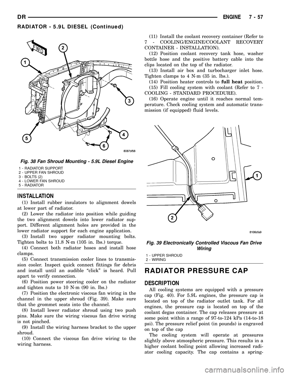
(7) Position the electronic viscous fan wiring in the
channel in the upper shroud (Fig. 39). Make sure
that the grommet seats into the channel.
(8) Install lower radiator shroud using two push
pins. Make sure the wiring viscous fan drive wiring
is not pinched.
(9) Install the wiring harness bracket to the upper
shroud.
(10) Connect the viscous fan drive wiring to the
wiring harness.(11) Install the coolant recovery container (Refer to
7 - COOLING/ENGINE/COOLANT RECOVERY
CONTAINER - INSTALLATION).
(12) Position coolant recovery tank hose, washer
bottle hose and the positive battery cable into the
clips located on the top of the radiator.
(13) Install air box and turbocharger inlet hose.
Tighten clamps to 4 N´m (35 in. lbs.).
(14) Position heater controls tofull heatposition.
(15) Fill cooling system with coolant (Refer to 7 -
COOLING - STANDARD PROCEDURE).
(16) Operate engine until it reaches normal tem-
perature. Check cooling system and automatic trans-
mission (if equipped) fluid levels.
RADIATOR PRESSURE CAP
DESCRIPTION
All cooling systems are equipped with a pressure
cap (Fig. 40). For 5.9L engines, the pressure cap is
located on top of the radiator outlet tank. For all
engines, the pressure cap is located on top of the
coolant degas container. The cap releases pressure at
some point within a range of 97-to-124 kPa (14-to-18
psi). The pressure relief point (in pounds) is engraved
on top of the cap
The cooling system will operate at pressures
slightly above atmospheric pressure. This results in a
higher coolant boiling point allowing increased radi-
ator cooling capacity. The cap contains a spring-
Fig. 38 Fan Shroud Mounting - 5.9L Diesel Engine
1 - RADIATOR SUPPORT
2 - UPPER FAN SHROUD
3 - BOLTS (2)
4 - LOWER FAN SHROUD
5 - RADIATOR
Fig. 39 Electronically Controlled Viscous Fan Drive
Wiring
1 - UPPER SHROUD
2 - WIRING
DRENGINE 7 - 57
RADIATOR - 5.9L DIESEL (Continued)
Page 434 of 2627
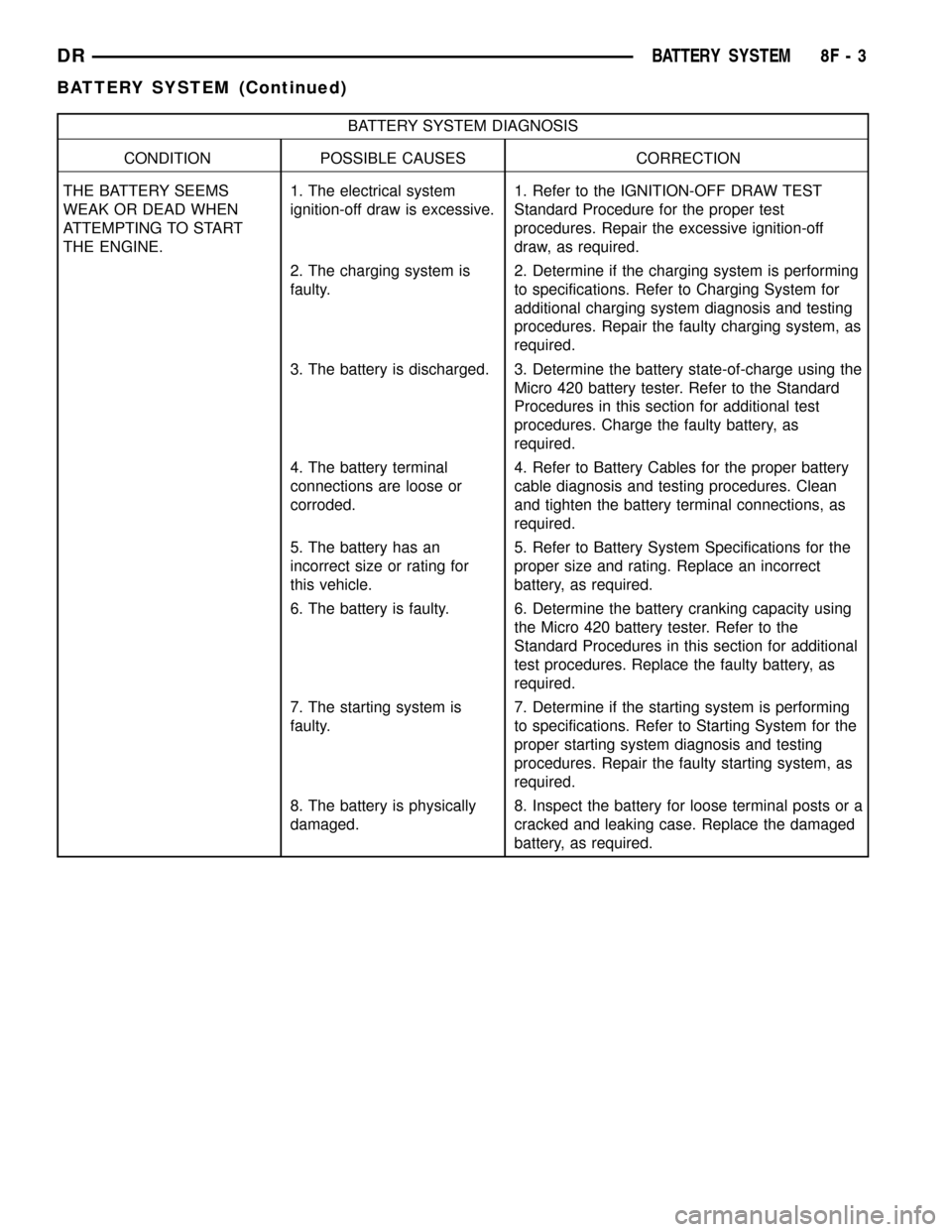
BATTERY SYSTEM DIAGNOSIS
CONDITION POSSIBLE CAUSES CORRECTION
THE BATTERY SEEMS
WEAK OR DEAD WHEN
ATTEMPTING TO START
THE ENGINE.1. The electrical system
ignition-off draw is excessive.1. Refer to the IGNITION-OFF DRAW TEST
Standard Procedure for the proper test
procedures. Repair the excessive ignition-off
draw, as required.
2. The charging system is
faulty.2. Determine if the charging system is performing
to specifications. Refer to Charging System for
additional charging system diagnosis and testing
procedures. Repair the faulty charging system, as
required.
3. The battery is discharged. 3. Determine the battery state-of-charge using the
Micro 420 battery tester. Refer to the Standard
Procedures in this section for additional test
procedures. Charge the faulty battery, as
required.
4. The battery terminal
connections are loose or
corroded.4. Refer to Battery Cables for the proper battery
cable diagnosis and testing procedures. Clean
and tighten the battery terminal connections, as
required.
5. The battery has an
incorrect size or rating for
this vehicle.5. Refer to Battery System Specifications for the
proper size and rating. Replace an incorrect
battery, as required.
6. The battery is faulty. 6. Determine the battery cranking capacity using
the Micro 420 battery tester. Refer to the
Standard Procedures in this section for additional
test procedures. Replace the faulty battery, as
required.
7. The starting system is
faulty.7. Determine if the starting system is performing
to specifications. Refer to Starting System for the
proper starting system diagnosis and testing
procedures. Repair the faulty starting system, as
required.
8. The battery is physically
damaged.8. Inspect the battery for loose terminal posts or a
cracked and leaking case. Replace the damaged
battery, as required.
DRBATTERY SYSTEM 8F - 3
BATTERY SYSTEM (Continued)
Page 437 of 2627
(4) Inspect the battery thermal guard (if equipped)
for tears, cracks, deformation or other damage.
Replace any battery thermal guard that has been
damaged.
(5) Inspect the battery built-in test indicator sight
glass (if equipped) for an indication of the battery
condition. If the battery is discharged, charge as
required. Refer to Standard Procedures for the
proper battery built-in indicator test procedures. Also
refer to Standard Procedures for the proper battery
charging procedures.
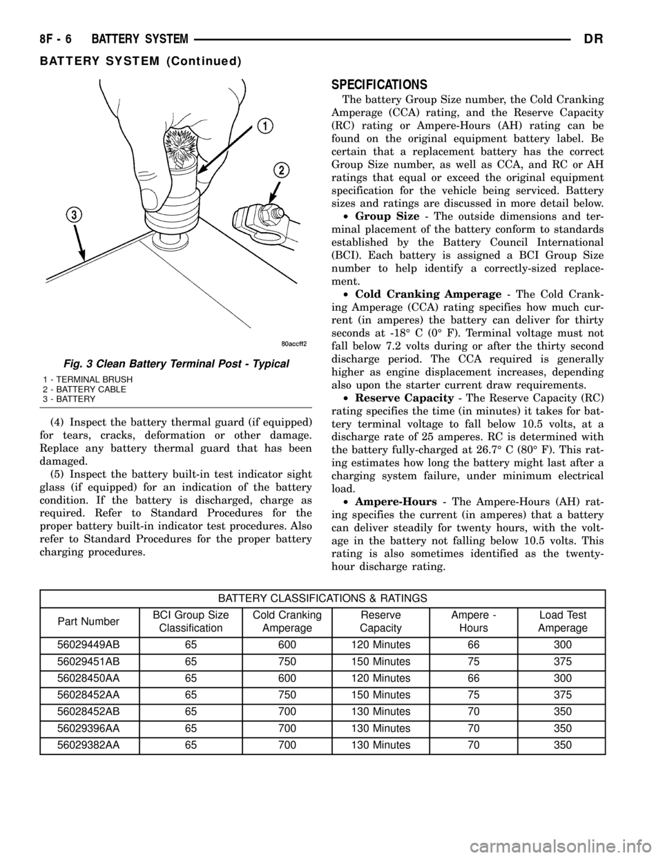
SPECIFICATIONS
The battery Group Size number, the Cold Cranking
Amperage (CCA) rating, and the Reserve Capacity
(RC) rating or Ampere-Hours (AH) rating can be
found on the original equipment battery label. Be
certain that a replacement battery has the correct
Group Size number, as well as CCA, and RC or AH
ratings that equal or exceed the original equipment
specification for the vehicle being serviced. Battery
sizes and ratings are discussed in more detail below.
²Group Size- The outside dimensions and ter-
minal placement of the battery conform to standards
established by the Battery Council International
(BCI). Each battery is assigned a BCI Group Size
number to help identify a correctly-sized replace-
ment.
²Cold Cranking Amperage- The Cold Crank-
ing Amperage (CCA) rating specifies how much cur-
rent (in amperes) the battery can deliver for thirty
seconds at -18É C (0É F). Terminal voltage must not
fall below 7.2 volts during or after the thirty second
discharge period. The CCA required is generally
higher as engine displacement increases, depending
also upon the starter current draw requirements.
²Reserve Capacity- The Reserve Capacity (RC)
rating specifies the time (in minutes) it takes for bat-
tery terminal voltage to fall below 10.5 volts, at a
discharge rate of 25 amperes. RC is determined with
the battery fully-charged at 26.7É C (80É F). This rat-
ing estimates how long the battery might last after a
charging system failure, under minimum electrical
load.
²Ampere-Hours- The Ampere-Hours (AH) rat-
ing specifies the current (in amperes) that a battery
can deliver steadily for twenty hours, with the volt-
age in the battery not falling below 10.5 volts. This
rating is also sometimes identified as the twenty-
hour discharge rating.
BATTERY CLASSIFICATIONS & RATINGS
Part NumberBCI Group Size
ClassificationCold Cranking
AmperageReserve
CapacityAmpere -
HoursLoad Test
Amperage
56029449AB 65 600 120 Minutes 66 300
56029451AB 65 750 150 Minutes 75 375
56028450AA 65 600 120 Minutes 66 300
56028452AA 65 750 150 Minutes 75 375
56028452AB 65 700 130 Minutes 70 350
56029396AA 65 700 130 Minutes 70 350
56029382AA 65 700 130 Minutes 70 350
Fig. 3 Clean Battery Terminal Post - Typical
1 - TERMINAL BRUSH
2 - BATTERY CABLE
3 - BATTERY
8F - 6 BATTERY SYSTEMDR
BATTERY SYSTEM (Continued)