Fuel pump DODGE RAM 1500 1998 2.G Workshop Manual
[x] Cancel search | Manufacturer: DODGE, Model Year: 1998, Model line: RAM 1500, Model: DODGE RAM 1500 1998 2.GPages: 2627
Page 26 of 2627
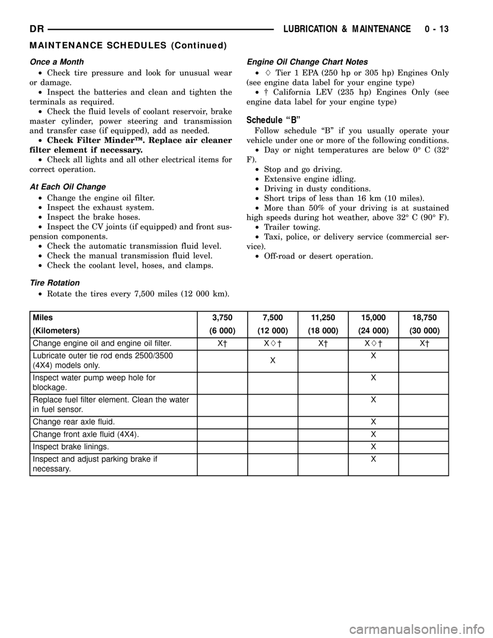
Once a Month
²Check tire pressure and look for unusual wear
or damage.
²Inspect the batteries and clean and tighten the
terminals as required.
²Check the fluid levels of coolant reservoir, brake
master cylinder, power steering and transmission
and transfer case (if equipped), add as needed.
²Check Filter MinderŸ. Replace air cleaner
filter element if necessary.
²Check all lights and all other electrical items for
correct operation.
At Each Oil Change
²Change the engine oil filter.
²Inspect the exhaust system.
²Inspect the brake hoses.
²Inspect the CV joints (if equipped) and front sus-
pension components.
²Check the automatic transmission fluid level.
²Check the manual transmission fluid level.
²Check the coolant level, hoses, and clamps.
Tire Rotation
²Rotate the tires every 7,500 miles (12 000 km).
Engine Oil Change Chart Notes
²LTier 1 EPA (250 hp or 305 hp) Engines Only
(see engine data label for your engine type)
²² California LEV (235 hp) Engines Only (see
engine data label for your engine type)
Schedule ªBº
Follow schedule ªBº if you usually operate your
vehicle under one or more of the following conditions.
²Day or night temperatures are below 0É C (32É
F).
²Stop and go driving.
²Extensive engine idling.
²Driving in dusty conditions.
²Short trips of less than 16 km (10 miles).
²More than 50% of your driving is at sustained
high speeds during hot weather, above 32É C (90É F).
²Trailer towing.
²Taxi, police, or delivery service (commercial ser-
vice).
²Off-road or desert operation.
Miles 3,750 7,500 11,250 15,000 18,750
(Kilometers) (6 000) (12 000) (18 000) (24 000) (30 000)
Change engine oil and engine oil filter. X² XL²X²XL²X²
Lubricate outer tie rod ends 2500/3500
(4X4) models only.XX
Inspect water pump weep hole for
blockage.X
Replace fuel filter element. Clean the water
in fuel sensor.X
Change rear axle fluid. X
Change front axle fluid (4X4). X
Inspect brake linings.X
Inspect and adjust parking brake if
necessary.X
DRLUBRICATION & MAINTENANCE 0 - 13
MAINTENANCE SCHEDULES (Continued)
Page 27 of 2627
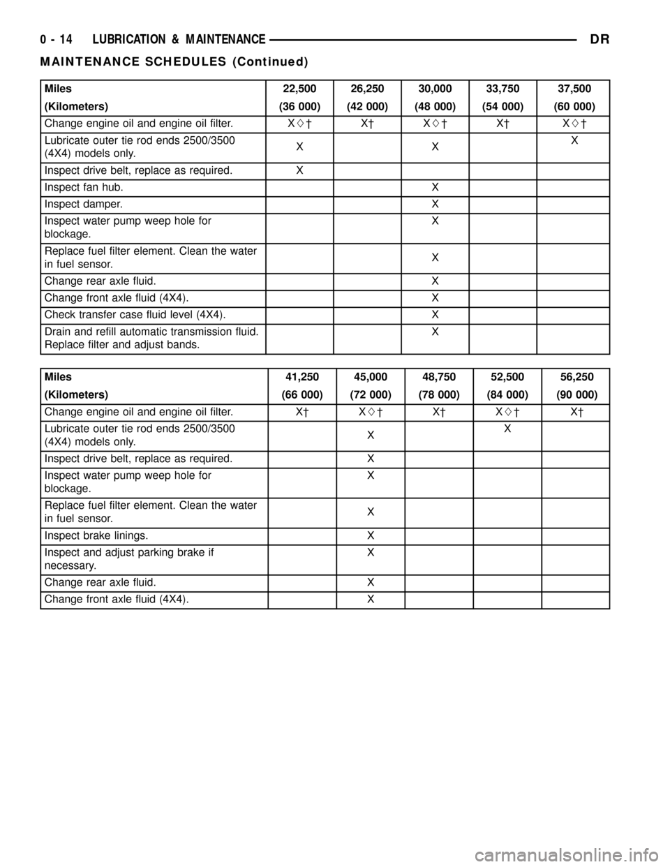
Miles 22,500 26,250 30,000 33,750 37,500
(Kilometers) (36 000) (42 000) (48 000) (54 000) (60 000)
Change engine oil and engine oil filter. XL²X²XL²X² XL²
Lubricate outer tie rod ends 2500/3500
(4X4) models only.XXX
Inspect drive belt, replace as required. X
Inspect fan hub. X
Inspect damper. X
Inspect water pump weep hole for
blockage.X
Replace fuel filter element. Clean the water
in fuel sensor.X
Change rear axle fluid. X
Change front axle fluid (4X4). X
Check transfer case fluid level (4X4). X
Drain and refill automatic transmission fluid.
Replace filter and adjust bands.X
Miles 41,250 45,000 48,750 52,500 56,250
(Kilometers) (66 000) (72 000) (78 000) (84 000) (90 000)
Change engine oil and engine oil filter. X² XL²X²XL²X²
Lubricate outer tie rod ends 2500/3500
(4X4) models only.XX
Inspect drive belt, replace as required. X
Inspect water pump weep hole for
blockage.X
Replace fuel filter element. Clean the water
in fuel sensor.X
Inspect brake linings. X
Inspect and adjust parking brake if
necessary.X
Change rear axle fluid. X
Change front axle fluid (4X4). X
0 - 14 LUBRICATION & MAINTENANCEDR
MAINTENANCE SCHEDULES (Continued)
Page 28 of 2627
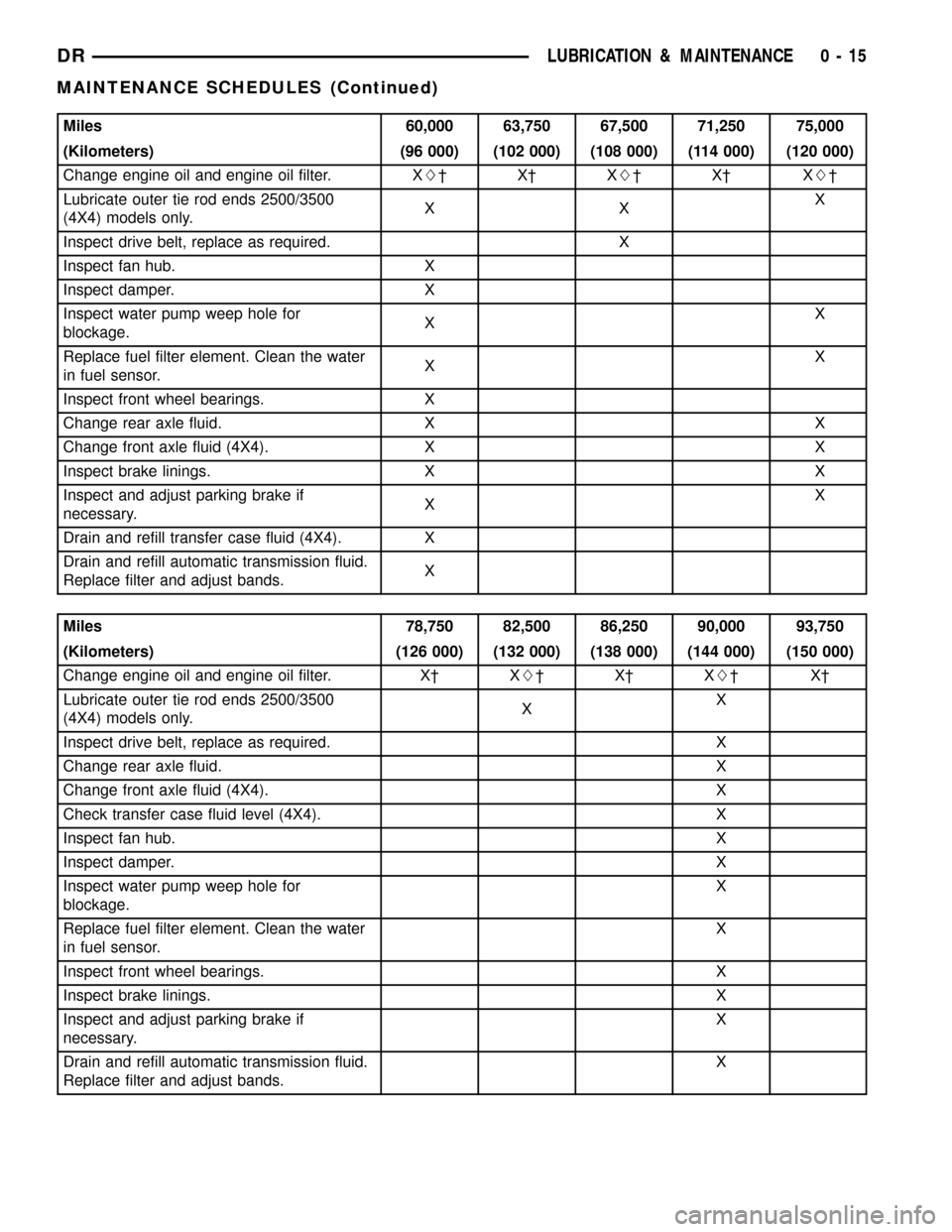
Miles 60,000 63,750 67,500 71,250 75,000
(Kilometers) (96 000) (102 000) (108 000) (114 000) (120 000)
Change engine oil and engine oil filter. XL²X²XL²X² XL²
Lubricate outer tie rod ends 2500/3500
(4X4) models only.XXX
Inspect drive belt, replace as required. X
Inspect fan hub. X
Inspect damper. X
Inspect water pump weep hole for
blockage.XX
Replace fuel filter element. Clean the water
in fuel sensor.XX
Inspect front wheel bearings. X
Change rear axle fluid. X X
Change front axle fluid (4X4). X X
Inspect brake linings. X X
Inspect and adjust parking brake if
necessary.XX
Drain and refill transfer case fluid (4X4). X
Drain and refill automatic transmission fluid.
Replace filter and adjust bands.X
Miles 78,750 82,500 86,250 90,000 93,750
(Kilometers) (126 000) (132 000) (138 000) (144 000) (150 000)
Change engine oil and engine oil filter. X² XL²X²XL²X²
Lubricate outer tie rod ends 2500/3500
(4X4) models only.XX
Inspect drive belt, replace as required. X
Change rear axle fluid. X
Change front axle fluid (4X4). X
Check transfer case fluid level (4X4). X
Inspect fan hub.X
Inspect damper.X
Inspect water pump weep hole for
blockage.X
Replace fuel filter element. Clean the water
in fuel sensor.X
Inspect front wheel bearings. X
Inspect brake linings.X
Inspect and adjust parking brake if
necessary.X
Drain and refill automatic transmission fluid.
Replace filter and adjust bands.X
DRLUBRICATION & MAINTENANCE 0 - 15
MAINTENANCE SCHEDULES (Continued)
Page 29 of 2627
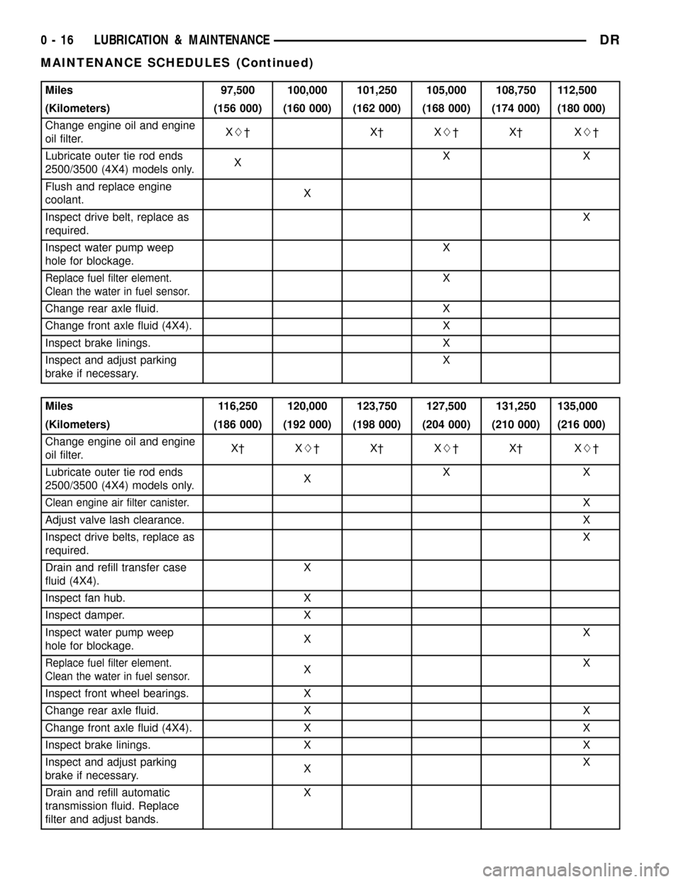
Miles 97,500 100,000 101,250 105,000 108,750 112,500
(Kilometers) (156 000) (160 000) (162 000) (168 000) (174 000) (180 000)
Change engine oil and engine
oil filter.XL²X²XL²X² XL²
Lubricate outer tie rod ends
2500/3500 (4X4) models only.XXX
Flush and replace engine
coolant.X
Inspect drive belt, replace as
required.X
Inspect water pump weep
hole for blockage.X
Replace fuel filter element.
Clean the water in fuel sensor.X
Change rear axle fluid. X
Change front axle fluid (4X4). X
Inspect brake linings. X
Inspect and adjust parking
brake if necessary.X
Miles 116,250 120,000 123,750 127,500 131,250 135,000
(Kilometers) (186 000) (192 000) (198 000) (204 000) (210 000) (216 000)
Change engine oil and engine
oil filter.X² XL²X²XL²X² XL²
Lubricate outer tie rod ends
2500/3500 (4X4) models only.XXX
Clean engine air filter canister.X
Adjust valve lash clearance.X
Inspect drive belts, replace as
required.X
Drain and refill transfer case
fluid (4X4).X
Inspect fan hub. X
Inspect damper. X
Inspect water pump weep
hole for blockage.XX
Replace fuel filter element.
Clean the water in fuel sensor.XX
Inspect front wheel bearings. X
Change rear axle fluid. X X
Change front axle fluid (4X4). X X
Inspect brake linings. X X
Inspect and adjust parking
brake if necessary.XX
Drain and refill automatic
transmission fluid. Replace
filter and adjust bands.X
0 - 16 LUBRICATION & MAINTENANCEDR
MAINTENANCE SCHEDULES (Continued)
Page 30 of 2627
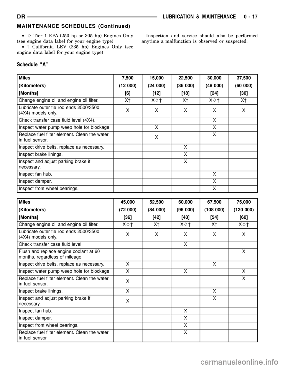
²LTier 1 EPA (250 hp or 305 hp) Engines Only
(see engine data label for your engine type)
²² California LEV (235 hp) Engines Only (see
engine data label for your engine type)Inspection and service should also be performed
anytime a malfunction is observed or suspected.
Schedule ªAº
Miles 7,500 15,000 22,500 30,000 37,500
(Kilometers) (12 000) (24 000) (36 000) (48 000) (60 000)
[Months] [6] [12] [18] [24] [30]
Change engine oil and engine oil filter. X² XL²X²XL²X²
Lubricate outer tie rod ends 2500/3500
(4X4) models only.XXXX X
Check transfer case fluid level (4X4). X
Inspect water pump weep hole for blockage X X
Replace fuel filter element. Clean the water
in fuel sensor.XX
Inspect drive belts, replace as necessary. X
Inspect brake linings. X
Inspect and adjust parking brake if
necessary.X
Inspect fan hub.X
Inspect damper.X
Inspect front wheel bearings. X
Miles 45,000 52,500 60,000 67,500 75,000
(Kilometers) (72 000) (84 000) (96 000) (108 000) (120 000)
[Months] [36] [42] [48] [54] [60]
Change engine oil and engine oil filter. XL²X²XL²X² XL²
Lubricate outer tie rod ends 2500/3500
(4X4) models only.XXXX X
Check transfer case fluid level. X
Flush and replace engine coolant at 60
months, regardless of mileage.X
Inspect drive belts, replace as necessary. X X
Inspect water pump weep hole for blockage X X X
Replace fuel filter element. Clean the water
in fuel sensor.XX
Inspect brake linings. X X
Inspect and adjust parking brake if
necessary.XX
Inspect fan hub. X
Inspect damper. X
Inspect front wheel bearings. X
Replace fuel filter element. Clean the water
in fuel sensorX
DRLUBRICATION & MAINTENANCE 0 - 17
MAINTENANCE SCHEDULES (Continued)
Page 31 of 2627
![DODGE RAM 1500 1998 2.G Workshop Manual Miles 82,500 90,000 97,500 100,000 105,000
(Kilometers) (132 000) (144 000) (156 000) (160 000) (168 000)
[Months] [66] [72] [78] [84]
Change engine oil and engine oil filter. X² XL²X² XL²
Lubrica DODGE RAM 1500 1998 2.G Workshop Manual Miles 82,500 90,000 97,500 100,000 105,000
(Kilometers) (132 000) (144 000) (156 000) (160 000) (168 000)
[Months] [66] [72] [78] [84]
Change engine oil and engine oil filter. X² XL²X² XL²
Lubrica](/img/12/5702/w960_5702-30.png)
Miles 82,500 90,000 97,500 100,000 105,000
(Kilometers) (132 000) (144 000) (156 000) (160 000) (168 000)
[Months] [66] [72] [78] [84]
Change engine oil and engine oil filter. X² XL²X² XL²
Lubricate outer tie rod ends 2500/3500
(4X4) models only.XXXX X
Flush and replace engine coolant, if not
done at 60 mos.X
Check transfer case fluid level (4X4). X
Inspect drive belt, replace as required. X
Inspect fan hub. X
Inspect damper. X
Inspect water pump weep hole for
blockage.XX
Replace fuel filter element. Clean the water
in fuel sensor.XX
Inspect front wheel bearings. X
Inspect brake linings. X
Inspect and adjust parking brake if
necessary.X
Drain and refill automatic transmission fluid.
Replace filter and adjust bands.X
Miles 112,500 120,000 127,500 135,000 142,500 150,000
(Kilometers) (181 000) (193 000) (205 000) (217 000) (229 000) (241 000)
[Months] [90] [96] [102] [108] [114] [150]
Change engine oil and engine
oil filter.X² XL²X²XL²X² XL²
Lubricate outer tie rod ends
2500/3500 (4X4) models only.XXXXX X
Flush and replace engine
coolant, if it has been 160
000 km (100, 000 miles) or 60
months since last change.X
Inspect drive belt, replace as
required.XX
Drain and refill transfer case
fluid (4X4).X
Check tranfer case fluid level
(4X4).X
Inspect fan hub. X X
Inspect damper. X X
Inspect water pump weep
hole for blockage.XXX
Replace fuel filter element.
Clean the water in fuel
sensor.XXX
0 - 18 LUBRICATION & MAINTENANCEDR
MAINTENANCE SCHEDULES (Continued)
Page 280 of 2627
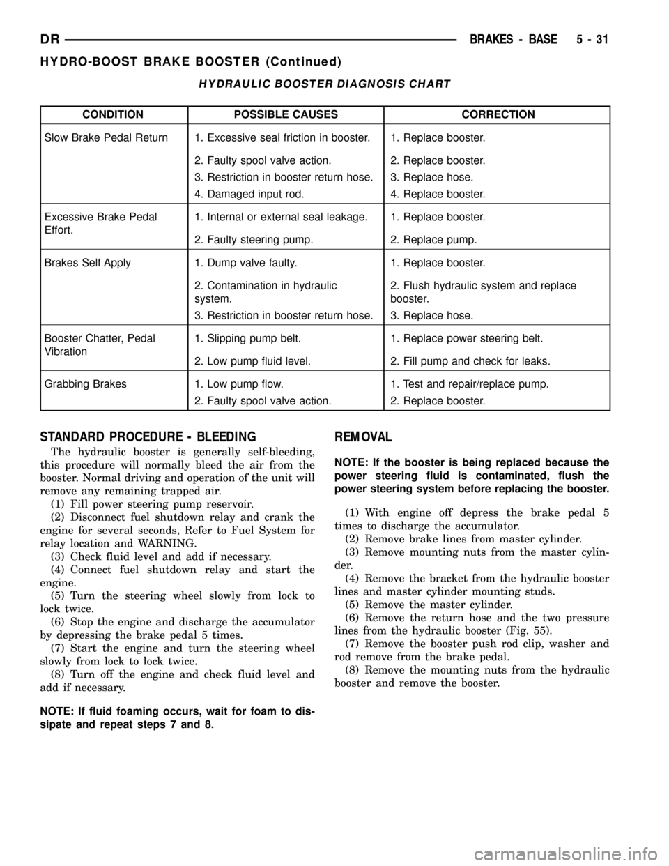
HYDRAULIC BOOSTER DIAGNOSIS CHART
CONDITION POSSIBLE CAUSES CORRECTION
Slow Brake Pedal Return 1. Excessive seal friction in booster. 1. Replace booster.
2. Faulty spool valve action. 2. Replace booster.
3. Restriction in booster return hose. 3. Replace hose.
4. Damaged input rod. 4. Replace booster.
Excessive Brake Pedal
Effort.1. Internal or external seal leakage. 1. Replace booster.
2. Faulty steering pump. 2. Replace pump.
Brakes Self Apply 1. Dump valve faulty. 1. Replace booster.
2. Contamination in hydraulic
system.2. Flush hydraulic system and replace
booster.
3. Restriction in booster return hose. 3. Replace hose.
Booster Chatter, Pedal
Vibration1. Slipping pump belt. 1. Replace power steering belt.
2. Low pump fluid level. 2. Fill pump and check for leaks.
Grabbing Brakes 1. Low pump flow. 1. Test and repair/replace pump.
2. Faulty spool valve action. 2. Replace booster.
STANDARD PROCEDURE - BLEEDING
The hydraulic booster is generally self-bleeding,
this procedure will normally bleed the air from the
booster. Normal driving and operation of the unit will
remove any remaining trapped air.
(1) Fill power steering pump reservoir.
(2) Disconnect fuel shutdown relay and crank the
engine for several seconds, Refer to Fuel System for
relay location and WARNING.
(3) Check fluid level and add if necessary.
(4) Connect fuel shutdown relay and start the
engine.
(5) Turn the steering wheel slowly from lock to
lock twice.
(6) Stop the engine and discharge the accumulator
by depressing the brake pedal 5 times.
(7) Start the engine and turn the steering wheel
slowly from lock to lock twice.
(8) Turn off the engine and check fluid level and
add if necessary.
NOTE: If fluid foaming occurs, wait for foam to dis-
sipate and repeat steps 7 and 8.
REMOVAL
NOTE: If the booster is being replaced because the
power steering fluid is contaminated, flush the
power steering system before replacing the booster.
(1) With engine off depress the brake pedal 5
times to discharge the accumulator.
(2) Remove brake lines from master cylinder.
(3) Remove mounting nuts from the master cylin-
der.
(4) Remove the bracket from the hydraulic booster
lines and master cylinder mounting studs.
(5) Remove the master cylinder.
(6) Remove the return hose and the two pressure
lines from the hydraulic booster (Fig. 55).
(7) Remove the booster push rod clip, washer and
rod remove from the brake pedal.
(8) Remove the mounting nuts from the hydraulic
booster and remove the booster.
DRBRAKES - BASE 5 - 31
HYDRO-BOOST BRAKE BOOSTER (Continued)
Page 353 of 2627

OPERATION
The heater warms the engine coolant providing
easier engine starting and faster warm-up in low
temperatures. Connecting the power cord to a
grounded 110-120 volt AC electrical outlet with a
grounded three wire extension cord provides the elec-
tricity needed to heat the element.
REMOVAL
(1) Disconnect the battery negative cables.
(2) Drain coolant from radiator and cylinder block
(Refer to 7 - COOLING - STANDARD PROCE-
DURE).
(3) Unscrew the power cord retaining cap and dis-
connect cord from heater element.
(4) Using a suitable size socket, loosen and remove
the block heater element (Fig. 9).
INSTALLATION
(1) Clean and inspect the threads in the cylinder
block.
(2) Coat heater element threads with Mopart
Thread Sealer with Teflon.
(3) Screw block heater into cylinder block and
tighten to 55 N´m (41 ft. lbs.).
(4) Connect block heater cord and tighten retain-
ing cap.
(5) Fill cooling system with recommended coolant
(Refer to 7 - COOLING - STANDARD PROCE-
DURE).
(6) Start and warm the engine.
(7) Check block heater for leaks.
ENGINE COOLANT
TEMPERATURE SENSOR
DESCRIPTION
The Engine Coolant Temperature (ECT) sensor is
used to sense engine coolant temperature. The sensor
protrudes into an engine water jacket.
The ECT sensor is a two-wire Negative Thermal
Coefficient (NTC) sensor. Meaning, as engine coolant
temperature increases, resistance (voltage) in the
sensor decreases. As temperature decreases, resis-
tance (voltage) in the sensor increases.
OPERATION
At key-on, the Powertrain Control Module (PCM)
sends out a regulated 5 volt signal to the ECT sensor.
The PCM then monitors the signal as it passes
through the ECT sensor to the sensor ground (sensor
return).
When the engine is cold, the PCM will operate in
Open Loop cycle. It will demand slightly richer air-
fuel mixtures and higher idle speeds. This is done
until normal operating temperatures are reached.
The PCM uses inputs from the ECT sensor for the
following calculations:
²for engine coolant temperature gauge operation
through CCD or PCI (J1850) communications
²Injector pulse-width
²Spark-advance curves
²ASD relay shut-down times
²Idle Air Control (IAC) motor key-on steps
²Pulse-width prime-shot during cranking
²O2 sensor closed loop times
²Purge solenoid on/off times
²EGR solenoid on/off times (if equipped)
²Leak Detection Pump operation (if equipped)
²Radiator fan relay on/off times (if equipped)
²Target idle speed
Fig. 8 Engine Block Heater ± 5.9L Diesel Engine
1 - BLOCK HEATER
Fig. 9 Block Heater - 5.9L Diesel Engine
1 - BLOCK HEATER
7 - 38 ENGINEDR
ENGINE BLOCK HEATER - 5.9L DIESEL (Continued)
Page 394 of 2627

RADIO NOISE SUPPRESSION
GROUND STRAP
DESCRIPTION
Radio noise suppression devices are factory-in-
stalled standard equipment on this vehicle. Radio
Frequency Interference (RFI) and ElectroMagnetic
Interference (EMI) can be produced by any on-board
or external source of electromagnetic energy. These
electromagnetic energy sources can radiate electro-
magnetic signals through the air, or conduct them
through the vehicle electrical system.
When the audio system converts RFI or EMI to an
audible acoustic wave form, it is referred to as radio
noise. This undesirable radio noise is generally man-
ifested in the form of ªbuzzing,º ªhissing,º ªpopping,º
ªclicking,º ªcrackling,º and/or ªwhirringº sounds. In
most cases, RFI and EMI radio noise can be sup-
pressed using a combination of vehicle and compo-
nent grounding, filtering and shielding techniques.
This vehicle is equipped with factory-installed radio
noise suppression devices that were designed to min-
imize exposure to typical sources of RFI and EMI;
thereby, minimizing radio noise complaints.
Factory-installed radio noise suppression is accom-
plished primarily through circuitry or devices that
are integral to the factory-installed radios, audio
power amplifiers and other on-board electrical com-
ponents such as generators, wiper motors, blower
motors, and fuel pumps that have been found to be
potential sources of RFI or EMI. External radio noise
suppression devices that are used on this vehicle to
control RFI or EMI, and can be serviced, include the
following:
²Engine-to-body ground strap- This length of
braided ground strap has an eyelet terminal connec-
tor crimped to each end. One end is secured to the
engine cylinder head(s). The other is secured to the
plenum at the exhaust heat shield forward/outer
attaching stud.
²Resistor-type spark plugs- This type of spark
plug has an internal resistor connected in series
between the spark plug terminal and the center elec-
trode to help reduce the production of electromag-
netic radiation that can result in radio noise.
OPERATION
There are two common strategies that can be used
to suppress Radio Frequency Interference (RFI) and
ElectroMagnetic Interference (EMI) radio noise. The
first suppression strategy involves preventing the
production of RFI and EMI electromagnetic signals
at their sources. The second suppression strategy
involves preventing the reception of RFI and EMIelectromagnetic signals by the audio system compo-
nents.
The use of braided ground straps in key locations
is part of the RFI and EMI prevention strategy.
These ground straps ensure adequate ground paths,
particularly for high current components such as
many of those found in the starting, charging, igni-
tion, engine control and transmission control sys-
tems. An insufficient ground path for any of these
high current components may result in radio noise
caused by induced voltages created as the high cur-
rent seeks alternative ground paths through compo-
nents or circuits intended for use by, or in close
proximity to the audio system components or circuits.
Preventing the reception of RFI and EMI is accom-
plished by ensuring that the audio system compo-
nents are correctly installed in the vehicle. Loose,
corroded or improperly soldered wire harness connec-
tions, improperly routed wiring and inadequate audio
system component grounding can all contribute to
the reception of RFI and EMI. A properly grounded
antenna body and radio chassis, as well as a shielded
antenna coaxial cable with clean and tight connec-
tions will each help reduce the potential for reception
of RFI and EMI.
REMOVAL
BED TO CAB
(1) Disconnect and isolate the battery negative
cable.
(2) Remove the attaching bolts and strap (Fig. 10).
Fig. 10 BED TO CAB GROUND STRAP
1 - BED
2 - CAB
3 - GROUND STRAP
4 - MOUNTING BOLTS
DRAUDIO/VIDEO 8A - 9
Page 410 of 2627

The PCI data bus can be monitored using the
DRBIIItscan tool. It is possible, however, for the bus
to pass all DRBIIIttests and still be faulty if the
voltage parameters are all within the specified range
and false messages are being sent.
CONTROLLER ANTILOCK
BRAKE
DESCRIPTION
The Controler Antilock Brake (CAB) is mounted to
the Hydraulic Control Unit (HCU) and operates the
ABS system (Fig. 1).
OPERATION
The CAB voltage source is through the ignition
switch in the RUN position. The CAB contains a self
check program that illuminates the ABS warning
light when a system fault is detected. Faults are
stored in a diagnostic program memory and are
accessible with the DRB III scan tool. ABS faults
remain in memory until cleared, or until after the
vehicle is started approximately 50 times. Stored
faults arenoterased if the battery is disconnected.
NOTE: If the CAB is being replaced with a new CAB
is must be reprogrammed with the use of a DRB III.
REMOVAL
(1) Remove the negative battery cable from the
battery.
(2) Pull up on the CAB harness connector release
and remove connector.
(3) Remove the CAB mounting bolts.
(4) Remove the pump connector from the CAB.
(5) Remove the CAB from the HCU.
INSTALLATION
NOTE: If the CAB is being replaced with a new CAB
is must be reprogrammed with the use of a DRB III.
(1) Install CAB to the HCU.
(2) Install the pump connector to the CAB.
(3) Install mounting bolts. Tighten to 2 N´m (16 in.
lbs.).
(4) Install the wiring harness connector to the
CAB and push down on the release to secure the con-
nector.
(5) Install negative battery cable to the battery.
DATA LINK CONNECTOR
DESCRIPTION - DATA LINK CONNECTOR
The Data Link Connector (DLC) is located at the
lower edge of the instrument panel near the steering
column.
OPERATION - DATA LINK CONNECTOR
The 16±way data link connector (diagnostic scan
tool connector) links the Diagnostic Readout Box
(DRB) scan tool or the Mopar Diagnostic System
(MDS) with the Powertrain Control Module (PCM).
ENGINE CONTROL MODULE
DESCRIPTION - ECM
The engine control module (ECM) for the 5.9L Die-
sel engine is bolted to the left side of the engine
below the intake manifold.
OPERATION - ECM
The main function of the Engine Control Module
(ECM) is to electrically control the fuel system. The
Powertrain Control Module (PCM)does notcontrol
the fuel system.
The ECM can adapt its programming to meet
changing operating conditions.If the ECM has
been replaced, flashed or re-calibrated, the
ECM must learn the Accelerator Pedal Position
Sensor (APPS) idle voltage. Failure to learn
this voltage may result in unnecessary diagnos-
tic trouble codes. Refer to ECM Removal/Instal-
lation for learning procedures.
The ECM receives input signals from various
switches and sensors. Based on these inputs, the
ECM regulates various engine and vehicle operations
through different system components. These compo-
nents are referred to asECM Outputs.The sensors
and switches that provide inputs to the ECM are
consideredECM Inputs.
Fig. 1 HYDRAULIC CONTROL UNIT
1 - HYDRAULIC CONTROL UNIT
2 - MOUNTING BOLTS
DRELECTRONIC CONTROL MODULES 8E - 3
COMMUNICATION (Continued)