Replace air cleaner DODGE RAM 1500 1998 2.G Workshop Manual
[x] Cancel search | Manufacturer: DODGE, Model Year: 1998, Model line: RAM 1500, Model: DODGE RAM 1500 1998 2.GPages: 2627
Page 20 of 2627
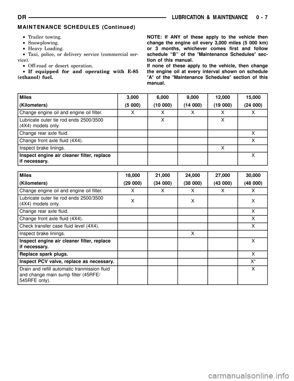
²Trailer towing.
²Snowplowing.
²Heavy Loading.
²Taxi, police, or delivery service (commercial ser-
vice).
²Off-road or desert operation.
²If equipped for and operating with E-85
(ethanol) fuel.NOTE: If ANY of these apply to the vehicle then
change the engine oil every 3,000 miles (5 000 km)
or 3 months, whichever comes first and follow
schedule ªBº of the(Maintenance Schedules(sec-
tion of this manual.
If none of these apply to the vehicle, then change
the engine oil at every interval shown on schedule
(A(of the(Maintenance Schedules(section of this
manual.
Miles 3,000 6,000 9,000 12,000 15,000
(Kilometers) (5 000) (10 000) (14 000) (19 000) (24 000)
Change engine oil and engine oil filter.XXXX X
Lubricate outer tie rod ends 2500/3500
(4X4) models only.XX
Change rear axle fluid.X
Change front axle fluid (4X4).X
Inspect brake linings.X
Inspect engine air cleaner filter, replace
if necessary.X
Miles 18,000 21,000 24,000 27,000 30,000
(Kilometers) (29 000) (34 000) (38 000) (43 000) (48 000)
Change engine oil and engine oil filter.XXXX X
Lubricate outer tie rod ends 2500/3500
(4X4) models only.XX X
Change rear axle fluid.X
Change front axle fluid (4X4).X
Check transfer case fluid level (4X4). X
Inspect brake linings. X
Inspect engine air cleaner filter, replace
if necessary.X
Replace spark plugs.X
Inspect PCV valve, replace as necessary.X*
Drain and refill automatic tranmission fluid
and change main sump filter (45RFE/
545RFE only).X
DRLUBRICATION & MAINTENANCE 0 - 7
MAINTENANCE SCHEDULES (Continued)
Page 21 of 2627
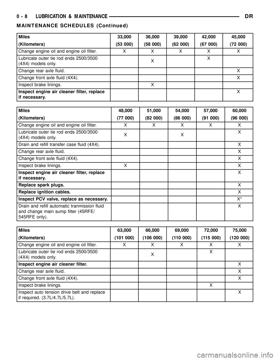
Miles 33,000 36,000 39,000 42,000 45,000
(Kilometers) (53 000) (58 000) (62 000) (67 000) (72 000)
Change engine oil and engine oil filter.XXXX X
Lubricate outer tie rod ends 2500/3500
(4X4) models only.XX
Change rear axle fluid.X
Change front axle fluid (4X4).X
Inspect brake linings. X
Inspect engine air cleaner filter, replace
if necessary.X
Miles 48,000 51,000 54,000 57,000 60,000
(Kilometers) (77 000) (82 000) (86 000) (91 000) (96 000)
Change engine oil and engine oil filter.XXXX X
Lubricate outer tie rod ends 2500/3500
(4X4) models only.XXX
Drain and refill transfer case fluid (4X4). X
Change rear axle fluid.X
Change front axle fluid (4X4).X
Inspect brake linings. X X
Inspect engine air cleaner filter, replace
if necessary.X
Replace spark plugs.X
Replace ignition cables.X
Inspect PCV valve, replace as necessary.X*
Drain and refill automatic tranmission fluid
and change main sump filter (45RFE/
545RFE only).X
Miles 63,000 66,000 69,000 72,000 75,000
(Kilometers) (101 000) (106 000) (110 000) (115 000) (120 000)
Change engine oil and engine oil filter. X X X X X
Lubricate outer tie rod ends 2500/3500
(4X4) models only.XX
Inspect engine air cleaner filter.X
Change rear axle fluid.X
Change front axle fluid (4X4).X
Inspect brake linings.X
Inspect auto tension drive belt and replace
if required. (3.7L/4.7L/5.7L).X
0 - 8 LUBRICATION & MAINTENANCEDR
MAINTENANCE SCHEDULES (Continued)
Page 22 of 2627
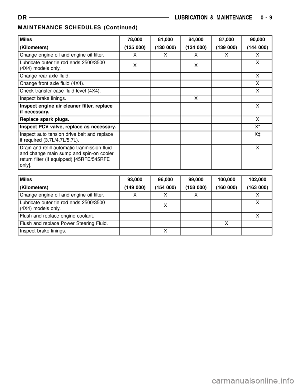
Miles 78,000 81,000 84,000 87,000 90,000
(Kilometers) (125 000) (130 000) (134 000) (139 000) (144 000)
Change engine oil and engine oil filter.XXXX X
Lubricate outer tie rod ends 2500/3500
(4X4) models only.XXX
Change rear axle fluid.X
Change front axle fluid (4X4).X
Check transfer case fluid level (4X4). X
Inspect brake linings. X
Inspect engine air cleaner filter, replace
if necessary.X
Replace spark plugs.X
Inspect PCV valve, replace as necessary.X*
Inspect auto tension drive belt and replace
if required (3.7L/4.7L/5.7L).X³
Drain and refill automatic tranmission fluid
and change main sump and spin-on cooler
return filter (if equipped) [45RFE/545RFE
only].X
Miles 93,000 96,000 99,000 100,000 102,000
(Kilometers) (149 000) (154 000) (158 000) (160 000) (163 000)
Change engine oil and engine oil filter. X X X X
Lubricate outer tie rod ends 2500/3500
(4X4) models only.XX
Flush and replace engine coolant.X
Flush and replace Power Steering Fluid. X
Inspect brake linings. X
DRLUBRICATION & MAINTENANCE 0 - 9
MAINTENANCE SCHEDULES (Continued)
Page 23 of 2627
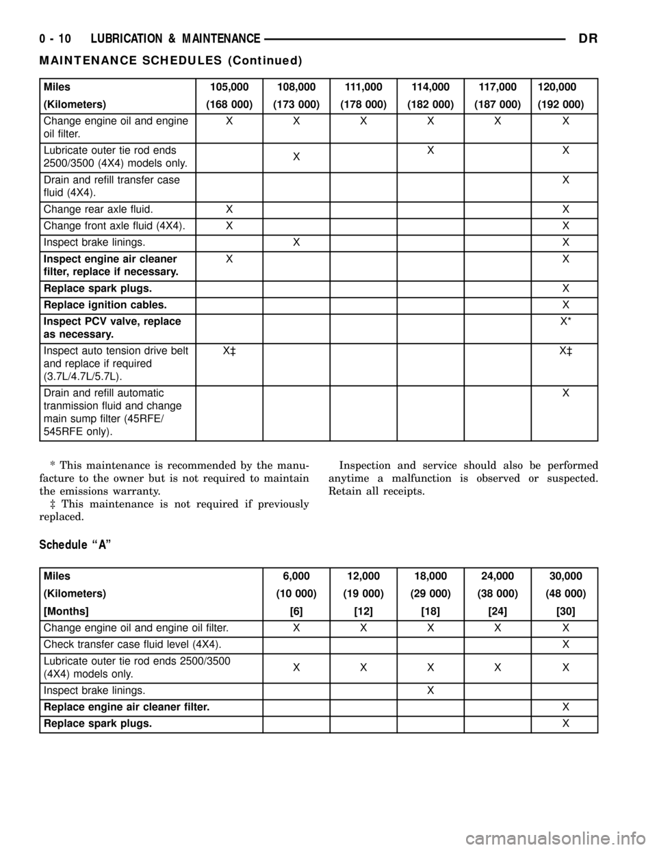
Miles 105,000 108,000 111,000 114,000 117,000 120,000
(Kilometers) (168 000) (173 000) (178 000) (182 000) (187 000) (192 000)
Change engine oil and engine
oil filter.XXXXX X
Lubricate outer tie rod ends
2500/3500 (4X4) models only.XXX
Drain and refill transfer case
fluid (4X4).X
Change rear axle fluid. X X
Change front axle fluid (4X4). X X
Inspect brake linings. X X
Inspect engine air cleaner
filter, replace if necessary.XX
Replace spark plugs.X
Replace ignition cables.X
Inspect PCV valve, replace
as necessary.X*
Inspect auto tension drive belt
and replace if required
(3.7L/4.7L/5.7L).X³ X³
Drain and refill automatic
tranmission fluid and change
main sump filter (45RFE/
545RFE only).X
* This maintenance is recommended by the manu-
facture to the owner but is not required to maintain
the emissions warranty.
³ This maintenance is not required if previously
replaced.Inspection and service should also be performed
anytime a malfunction is observed or suspected.
Retain all receipts.
Schedule ªAº
Miles 6,000 12,000 18,000 24,000 30,000
(Kilometers) (10 000) (19 000) (29 000) (38 000) (48 000)
[Months] [6] [12] [18] [24] [30]
Change engine oil and engine oil filter.XXXX X
Check transfer case fluid level (4X4). X
Lubricate outer tie rod ends 2500/3500
(4X4) models only.XXXX X
Inspect brake linings. X
Replace engine air cleaner filter.X
Replace spark plugs.X
0 - 10 LUBRICATION & MAINTENANCEDR
MAINTENANCE SCHEDULES (Continued)
Page 24 of 2627
![DODGE RAM 1500 1998 2.G Workshop Manual Miles 36,000 42,000 48,000 54,000 60,000 66,000
(Kilometers) (58 000) (67 000) (77 000) (84 000) (96 000) (106 000)
[Months] [36] [42] [48] [54] [60] [66]
Change engine oil and engine
oil filter.XXXXX DODGE RAM 1500 1998 2.G Workshop Manual Miles 36,000 42,000 48,000 54,000 60,000 66,000
(Kilometers) (58 000) (67 000) (77 000) (84 000) (96 000) (106 000)
[Months] [36] [42] [48] [54] [60] [66]
Change engine oil and engine
oil filter.XXXXX](/img/12/5702/w960_5702-23.png)
Miles 36,000 42,000 48,000 54,000 60,000 66,000
(Kilometers) (58 000) (67 000) (77 000) (84 000) (96 000) (106 000)
[Months] [36] [42] [48] [54] [60] [66]
Change engine oil and engine
oil filter.XXXXX
X
Check transfer case fluid level
(4X4).X
Lubricate outer tie rod ends
2500/3500 (4X4) models only.XXXXX X
Flush and replace engine
coolant at 60 months,
regardless of mileage.X
Inspect brake linings. X X
Replace engine air cleaner
filter.X
Replace spark plugs.X
Inspect PCV valve, replace
as necessary.X*
Replace ignition cables.X
Miles 72,000 78,000 84,000 90,000 96,000 100,000
(Kilometers) (115000) (125 000) (134 000) (144 000) (154 000) 160 000
[Months] [72] [78] [84] [90] [96]
Change engine oil and engine
oil filter.XXXXX
Lubricate outer tie rod ends
2500/3500 (4X4) models only.XXXXX
Check transfer case fluid level
(4X4).X
Flush and replace Power
Steering Fluid.X
Inspect brake linings. X X
Replace engine air cleaner
filter.X
Replace spark plugs.X
Inspect PCV valve, replace
as necessary.X*
Inspect auto tension drive belt
and replace if required
(3.7L/4.7L/5.7L).X
Drain and refill automatic
tranmission fluid and change
main sump filter and spin-on
cooler return filter (if
equipped) [45RFE/545RFE
only].X
DRLUBRICATION & MAINTENANCE 0 - 11
MAINTENANCE SCHEDULES (Continued)
Page 25 of 2627
![DODGE RAM 1500 1998 2.G Workshop Manual Miles 102,000 108,000 114,000 120,000
(Kilometers) (163 000) (173 000) (182 000) (192 000)
[Months] [102] [108] [114] [120]
Change engine oil and engine oil filter. X X X X
Drain and refill transfer c DODGE RAM 1500 1998 2.G Workshop Manual Miles 102,000 108,000 114,000 120,000
(Kilometers) (163 000) (173 000) (182 000) (192 000)
[Months] [102] [108] [114] [120]
Change engine oil and engine oil filter. X X X X
Drain and refill transfer c](/img/12/5702/w960_5702-24.png)
Miles 102,000 108,000 114,000 120,000
(Kilometers) (163 000) (173 000) (182 000) (192 000)
[Months] [102] [108] [114] [120]
Change engine oil and engine oil filter. X X X X
Drain and refill transfer case fluid (4X4). X
Flush and replace engine coolant, if not done at 60 mos. X
Lubricate outer tie rod ends 2500/3500 (4X4) models
only.XXX X
Inspect brake linings. X
Inspect auto tension drive belt and replace if required
(3.7L/4.7L/5.7L).X³X³
Replace ignition cables.X
Replace engine air cleaner filter.X
Replace spark plugs.X
Inspect PCV Valve, replace as necessary X*
* This maintenance is recommended by the manu-
facture to the owner but is not required to maintain
the emissions warranty.
³ This maintenance is not required if previously
replaced.
Inspection and service should also be performed
anytime a malfunction is observed or suspected.
WARNING: You can be badly injured working on or
around a motor vehicle. Do only that service work
for which you have the knowledge and the right
equipment. If you have any doubt about your ability
to perform a service job, take your vehicle to a
competent mechanic.
MAINTENANCE SCHEDULES Ð 24±VALVE
CUMMINS TURBO DIESEL
There are two maintenance schedules that show
therequiredservice for your vehicle.
First is ScheduleªBº. It is for vehicles that are
operated under the conditions that are listed below
and at the beginning of the schedule.
²Day or night temperatures are below 0É C (32É
F).
²Stop and go driving.
²Extensive engine idling.
²Driving in dusty conditions.
²Short trips of less than 16 km (10 miles).
²More than 50% of your driving is at sustained
high speeds during hot weather, above 32É C (90É F).²Trailer towing.
²Taxi, police, or delivery service (commercial ser-
vice).
²Off-road or desert operation.
NOTE: Most vehicles are operated under the condi-
tions listed for Schedule(B(.
Second is ScheduleªAº. It is for vehicles that are
not operated under any of the conditions listed under
Schedule9B9.
Use the schedule that best describes your driving
conditions. Where time and mileage are listed, follow
the interval that occurs first.
CAUTION: Failure to perform the required mainte-
nance items may result in damage to the vehicle.At Each Stop for Fuel
²Check the engine oil level about 15 minutes
after a fully warmed engine is shut off. Checking the
oil level while the vehicle is on level ground will
improve the accuracy of the oil level reading. Add oil
only when the level is at or below the ADD or MIN
mark.
²Check the windshield washer solvent and add if
required.
²Drain water from the fuel filter.
0 - 12 LUBRICATION & MAINTENANCEDR
MAINTENANCE SCHEDULES (Continued)
Page 26 of 2627
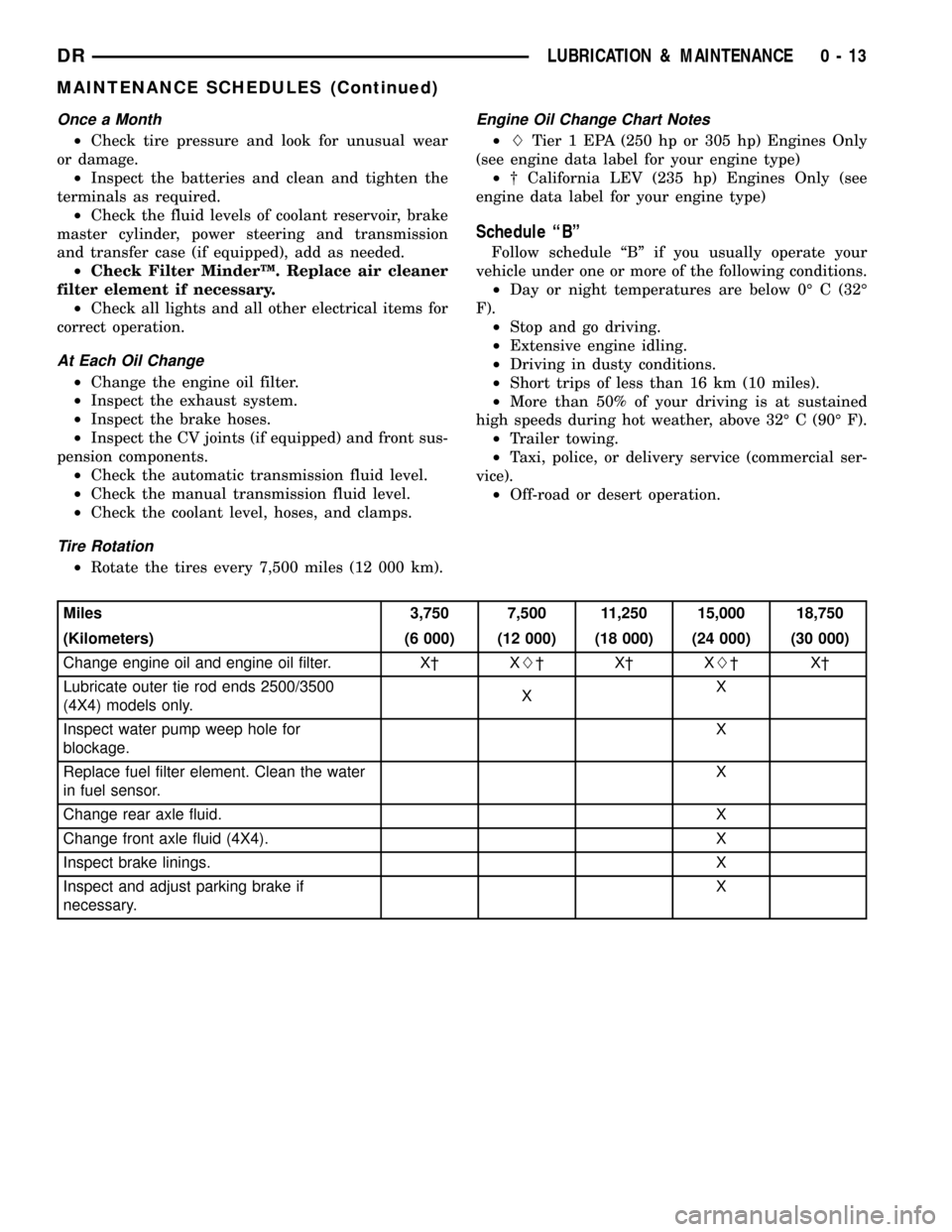
Once a Month
²Check tire pressure and look for unusual wear
or damage.
²Inspect the batteries and clean and tighten the
terminals as required.
²Check the fluid levels of coolant reservoir, brake
master cylinder, power steering and transmission
and transfer case (if equipped), add as needed.
²Check Filter MinderŸ. Replace air cleaner
filter element if necessary.
²Check all lights and all other electrical items for
correct operation.
At Each Oil Change
²Change the engine oil filter.
²Inspect the exhaust system.
²Inspect the brake hoses.
²Inspect the CV joints (if equipped) and front sus-
pension components.
²Check the automatic transmission fluid level.
²Check the manual transmission fluid level.
²Check the coolant level, hoses, and clamps.
Tire Rotation
²Rotate the tires every 7,500 miles (12 000 km).
Engine Oil Change Chart Notes
²LTier 1 EPA (250 hp or 305 hp) Engines Only
(see engine data label for your engine type)
²² California LEV (235 hp) Engines Only (see
engine data label for your engine type)
Schedule ªBº
Follow schedule ªBº if you usually operate your
vehicle under one or more of the following conditions.
²Day or night temperatures are below 0É C (32É
F).
²Stop and go driving.
²Extensive engine idling.
²Driving in dusty conditions.
²Short trips of less than 16 km (10 miles).
²More than 50% of your driving is at sustained
high speeds during hot weather, above 32É C (90É F).
²Trailer towing.
²Taxi, police, or delivery service (commercial ser-
vice).
²Off-road or desert operation.
Miles 3,750 7,500 11,250 15,000 18,750
(Kilometers) (6 000) (12 000) (18 000) (24 000) (30 000)
Change engine oil and engine oil filter. X² XL²X²XL²X²
Lubricate outer tie rod ends 2500/3500
(4X4) models only.XX
Inspect water pump weep hole for
blockage.X
Replace fuel filter element. Clean the water
in fuel sensor.X
Change rear axle fluid. X
Change front axle fluid (4X4). X
Inspect brake linings.X
Inspect and adjust parking brake if
necessary.X
DRLUBRICATION & MAINTENANCE 0 - 13
MAINTENANCE SCHEDULES (Continued)
Page 302 of 2627
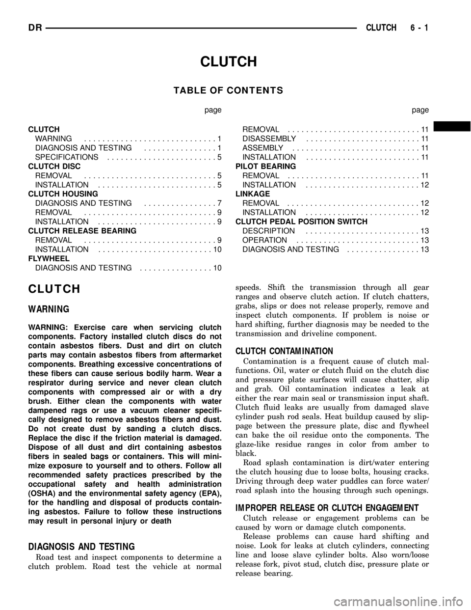
CLUTCH
TABLE OF CONTENTS
page page
CLUTCH
WARNING.............................1
DIAGNOSIS AND TESTING................1
SPECIFICATIONS........................5
CLUTCH DISC
REMOVAL.............................5
INSTALLATION..........................5
CLUTCH HOUSING
DIAGNOSIS AND TESTING................7
REMOVAL.............................9
INSTALLATION..........................9
CLUTCH RELEASE BEARING
REMOVAL.............................9
INSTALLATION.........................10
FLYWHEEL
DIAGNOSIS AND TESTING................10REMOVAL.............................11
DISASSEMBLY.........................11
ASSEMBLY............................11
INSTALLATION.........................11
PILOT BEARING
REMOVAL.............................11
INSTALLATION.........................12
LINKAGE
REMOVAL.............................12
INSTALLATION.........................12
CLUTCH PEDAL POSITION SWITCH
DESCRIPTION.........................13
OPERATION...........................13
DIAGNOSIS AND TESTING................13
CLUTCH
WARNING
WARNING: Exercise care when servicing clutch
components. Factory installed clutch discs do not
contain asbestos fibers. Dust and dirt on clutch
parts may contain asbestos fibers from aftermarket
components. Breathing excessive concentrations of
these fibers can cause serious bodily harm. Wear a
respirator during service and never clean clutch
components with compressed air or with a dry
brush. Either clean the components with water
dampened rags or use a vacuum cleaner specifi-
cally designed to remove asbestos fibers and dust.
Do not create dust by sanding a clutch discs.
Replace the disc if the friction material is damaged.
Dispose of all dust and dirt containing asbestos
fibers in sealed bags or containers. This will mini-
mize exposure to yourself and to others. Follow all
recommended safety practices prescribed by the
occupational safety and health administration
(OSHA) and the environmental safety agency (EPA),
for the handling and disposal of products contain-
ing asbestos. Failure to follow these instructions
may result in personal injury or death
DIAGNOSIS AND TESTING
Road test and inspect components to determine a
clutch problem. Road test the vehicle at normalspeeds. Shift the transmission through all gear
ranges and observe clutch action. If clutch chatters,
grabs, slips or does not release properly, remove and
inspect clutch components. If problem is noise or
hard shifting, further diagnosis may be needed to the
transmission and driveline component.
CLUTCH CONTAMINATION
Contamination is a frequent cause of clutch mal-
functions. Oil, water or clutch fluid on the clutch disc
and pressure plate surfaces will cause chatter, slip
and grab. Oil contamination indicates a leak at
either the rear main seal or transmission input shaft.
Clutch fluid leaks are usually from damaged slave
cylinder push rod seals. Heat buildup caused by slip-
page between the pressure plate, disc and flywheel
can bake the oil residue onto the components. The
glaze-like residue ranges in color from amber to
black.
Road splash contamination is dirt/water entering
the clutch housing due to loose bolts, housing cracks.
Driving through deep water puddles can force water/
road splash into the housing through such openings.
IMPROPER RELEASE OR CLUTCH ENGAGEMENT
Clutch release or engagement problems can be
caused by worn or damage clutch components.
Release problems can cause hard shifting and
noise. Look for leaks at clutch cylinders, connecting
line and loose slave cylinder bolts. Also worn/loose
release fork, pivot stud, clutch disc, pressure plate or
release bearing.
DRCLUTCH 6 - 1
Page 332 of 2627

STANDARD PROCEDURE
STANDARD PROCEDURE - COOLANT LEVEL
CHECK
NOTE: Do not remove radiator cap for routine cool-
ant level inspections. The coolant level can be
checked at coolant recovery bottle or the coolant
degas bottle.
WARNING: DO NOT REMOVE OR LOOSEN THE
RADIATOR CAP WITH THE COOLING SYSTEM HOT
AND UNDER PRESSURE. SERIOUS BURNS FROM
COOLANT OR HIGH PRESSURE STEAM CAN
OCCUR.
The coolant reserve/overflow system provides a
quick method for determining the coolant level with-
out removing the radiator pressure cap. With the
engine at normal operating temperature and idling,
observe the level of the coolant on the external level
indicator on the side of the coolant reserve / overflow
bottle. The coolant level should be between the MIN
and MAX marks. If the coolant is below the MIN
mark, add a 50/50 mixture of antifreeze and water to
the bottle until the level reaches the MIN mark.Do
Not Overfill the bottle by adding fluid above
the MAX line.This may cause coolant to spill onto
the ground during subsequent vehicle operation.
STANDARD PROCEDURE - COOLING SYSTEM
CLEANING/REVERSE FLUSHING
CLEANING
Drain the cooling system and refill with water. Run
the engine with the radiator cap installed until the
upper radiator hose is hot. Stop the engine and drain
the water from system. If the water is dirty, fill the
system with water, run the engine and drain the sys-
tem. Repeat this procedure until the water drains
clean.
REVERSE FLUSHING
Reverse flushing of the cooling system is the forc-
ing of water through the cooling system. This is done
using air pressure in the opposite direction of normal
coolant flow. It is usually only necessary with very
dirty systems with evidence of partial plugging.
REVERSE FLUSHING RADIATOR
Disconnect the radiator hoses from the radiator
inlet and outlet. Attach a section of the radiator hose
to the radiator bottom outlet fitting and insert the
flushing gun. Connect a water supply hose and air
supply hose to the flushing gun.CAUTION: Internal radiator pressure must not
exceed 138 kPa (20 psi) as damage to radiator may
result.
Allow the radiator to fill with water. When the
radiator is filled, apply air in short blasts. Allow the
radiator to refill between blasts. Continue this
reverse flushing until clean water flows out through
the rear of the radiator cooling tube passages.
REVERSE FLUSHING ENGINE
Drain the cooling system. Remove the thermostat
housing and thermostat. Install the thermostat hous-
ing. Disconnect the radiator upper hose from the
radiator and attach the flushing gun to the hose. Dis-
connect the radiator lower hose from the water pump
and attach a lead-away hose to the water pump inlet
fitting.
CAUTION: On vehicles equipped with a heater water
control valve, be sure the heater control valve is
closed (heat off). This will prevent coolant flow with
scale and other deposits from entering the heater
core.
Connect the water supply hose and air supply hose
to flushing gun. Allow the engine to fill with water.
When the engine is filled, apply air in short blasts,
allowing the system to fill between air blasts. Con-
tinue until clean water flows through the lead away
hose.
Remove the lead away hose, flushing gun, water
supply hose and air supply hose. Remove the thermo-
stat housing and install the thermostat. Install the
thermostat housing with a replacement gasket. Refer
to Thermostat Replacement. Connect the radiator
hoses. Refill the cooling system with the correct anti-
freeze/water mixture. Refer to Refilling the Cooling
System.
CHEMICAL CLEANING
In some instances, use a radiator cleaner (Mopart
Radiator Kleen or equivalent) before flushing. This
will soften scale and other deposits and aid flushing
operation.
CAUTION: Follow manufacturers instructions when
using these products.
STANDARD PROCEDURE - DRAINING COOLING
SYSTEM - ALL GAS ENGINES
WARNING: DO NOT REMOVE CYLINDER BLOCK
DRAIN PLUGS OR LOOSEN RADIATOR DRAIN-
COCK WITH SYSTEM HOT AND UNDER PRESSURE.
SERIOUS BURNS FROM COOLANT CAN OCCUR.
DRCOOLING 7 - 17
COOLING (Continued)
Page 388 of 2627
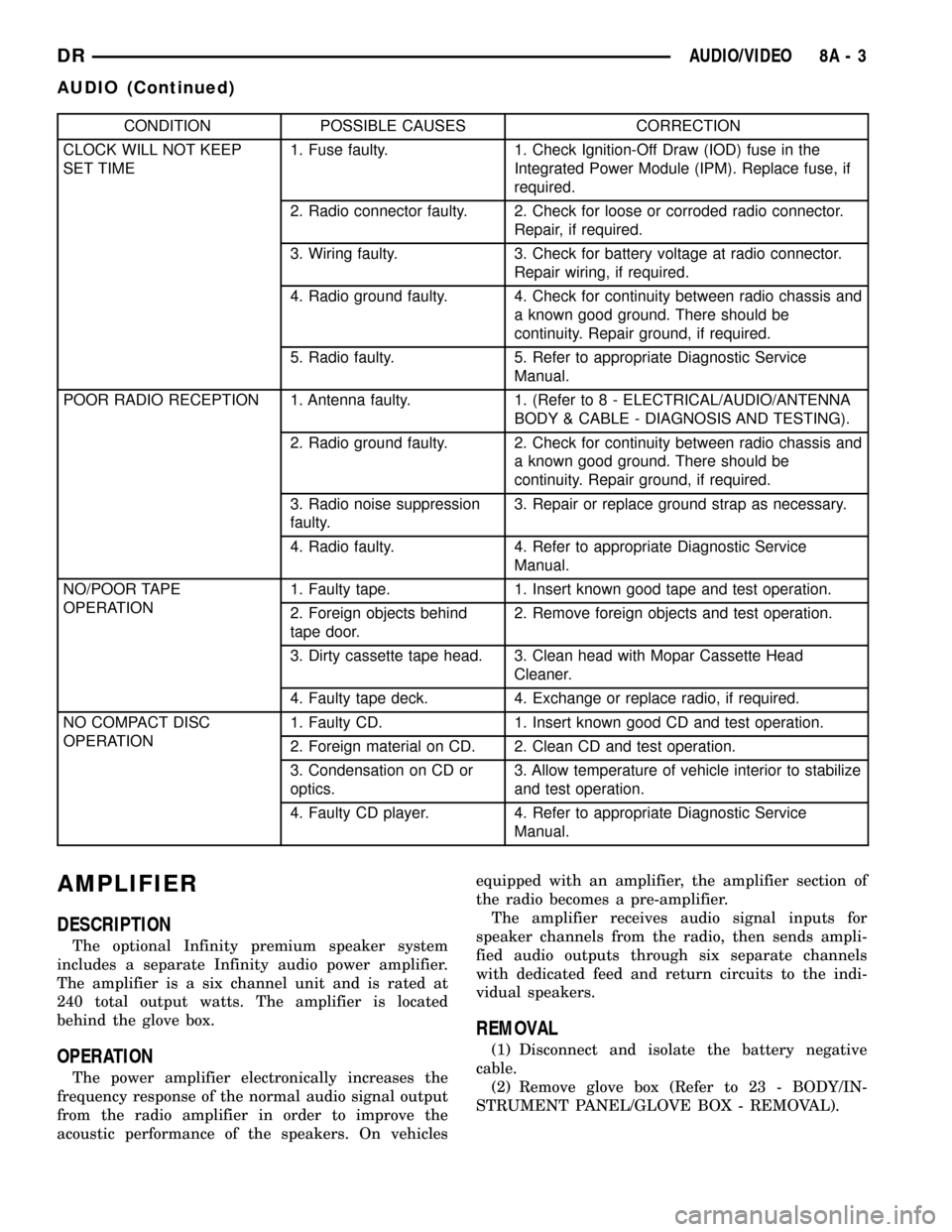
CONDITION POSSIBLE CAUSES CORRECTION
CLOCK WILL NOT KEEP
SET TIME1. Fuse faulty. 1. Check Ignition-Off Draw (IOD) fuse in the
Integrated Power Module (IPM). Replace fuse, if
required.
2. Radio connector faulty. 2. Check for loose or corroded radio connector.
Repair, if required.
3. Wiring faulty. 3. Check for battery voltage at radio connector.
Repair wiring, if required.
4. Radio ground faulty. 4. Check for continuity between radio chassis and
a known good ground. There should be
continuity. Repair ground, if required.
5. Radio faulty. 5. Refer to appropriate Diagnostic Service
Manual.
POOR RADIO RECEPTION 1. Antenna faulty. 1. (Refer to 8 - ELECTRICAL/AUDIO/ANTENNA
BODY & CABLE - DIAGNOSIS AND TESTING).
2. Radio ground faulty. 2. Check for continuity between radio chassis and
a known good ground. There should be
continuity. Repair ground, if required.
3. Radio noise suppression
faulty.3. Repair or replace ground strap as necessary.
4. Radio faulty. 4. Refer to appropriate Diagnostic Service
Manual.
NO/POOR TAPE
OPERATION1. Faulty tape. 1. Insert known good tape and test operation.
2. Foreign objects behind
tape door.2. Remove foreign objects and test operation.
3. Dirty cassette tape head. 3. Clean head with Mopar Cassette Head
Cleaner.
4. Faulty tape deck. 4. Exchange or replace radio, if required.
NO COMPACT DISC
OPERATION1. Faulty CD. 1. Insert known good CD and test operation.
2. Foreign material on CD. 2. Clean CD and test operation.
3. Condensation on CD or
optics.3. Allow temperature of vehicle interior to stabilize
and test operation.
4. Faulty CD player. 4. Refer to appropriate Diagnostic Service
Manual.
AMPLIFIER
DESCRIPTION
The optional Infinity premium speaker system
includes a separate Infinity audio power amplifier.
The amplifier is a six channel unit and is rated at
240 total output watts. The amplifier is located
behind the glove box.
OPERATION
The power amplifier electronically increases the
frequency response of the normal audio signal output
from the radio amplifier in order to improve the
acoustic performance of the speakers. On vehiclesequipped with an amplifier, the amplifier section of
the radio becomes a pre-amplifier.
The amplifier receives audio signal inputs for
speaker channels from the radio, then sends ampli-
fied audio outputs through six separate channels
with dedicated feed and return circuits to the indi-
vidual speakers.
REMOVAL
(1) Disconnect and isolate the battery negative
cable.
(2) Remove glove box (Refer to 23 - BODY/IN-
STRUMENT PANEL/GLOVE BOX - REMOVAL).
DRAUDIO/VIDEO 8A - 3
AUDIO (Continued)