Spring leaf DODGE RAM 1500 1998 2.G Workshop Manual
[x] Cancel search | Manufacturer: DODGE, Model Year: 1998, Model line: RAM 1500, Model: DODGE RAM 1500 1998 2.GPages: 2627
Page 33 of 2627
CAUTION: Do not crank starter motor on disabled
vehicle for more than 15 seconds, starter will over-
heat and could fail.
(7) Allow battery in disabled vehicle to charge to
at least 12.4 volts (75% charge) before attempting to
start engine. If engine does not start within 15 sec-
onds, stop cranking engine and allow starter to cool
(15 min.), before cranking again.
DISCONNECT CABLE CLAMPS AS FOLLOWS:
²Disconnect BLACK cable clamp from engine
ground on disabled vehicle.
²When using a Booster vehicle, disconnect
BLACK cable clamp from battery negative terminal.
Disconnect RED cable clamp from battery positive
terminal.
²Disconnect RED cable clamp from battery posi-
tive terminal on disabled vehicle.
HOISTING
STANDARD PROCEDURE - HOISTING
Refer to the Owner's Manual for emergency vehicle
lifting procedures.
WARNING: THE HOISTING AND JACK LIFTING
POINTS PROVIDED ARE FOR A COMPLETE VEHI-
CLE. WHEN A CHASSIS OR DRIVETRAIN COMPO-
NENT IS REMOVED FROM A VEHICLE, THE
CENTER OF GRAVITY IS ALTERED MAKING SOME
HOISTING CONDITIONS UNSTABLE. PROPERLY
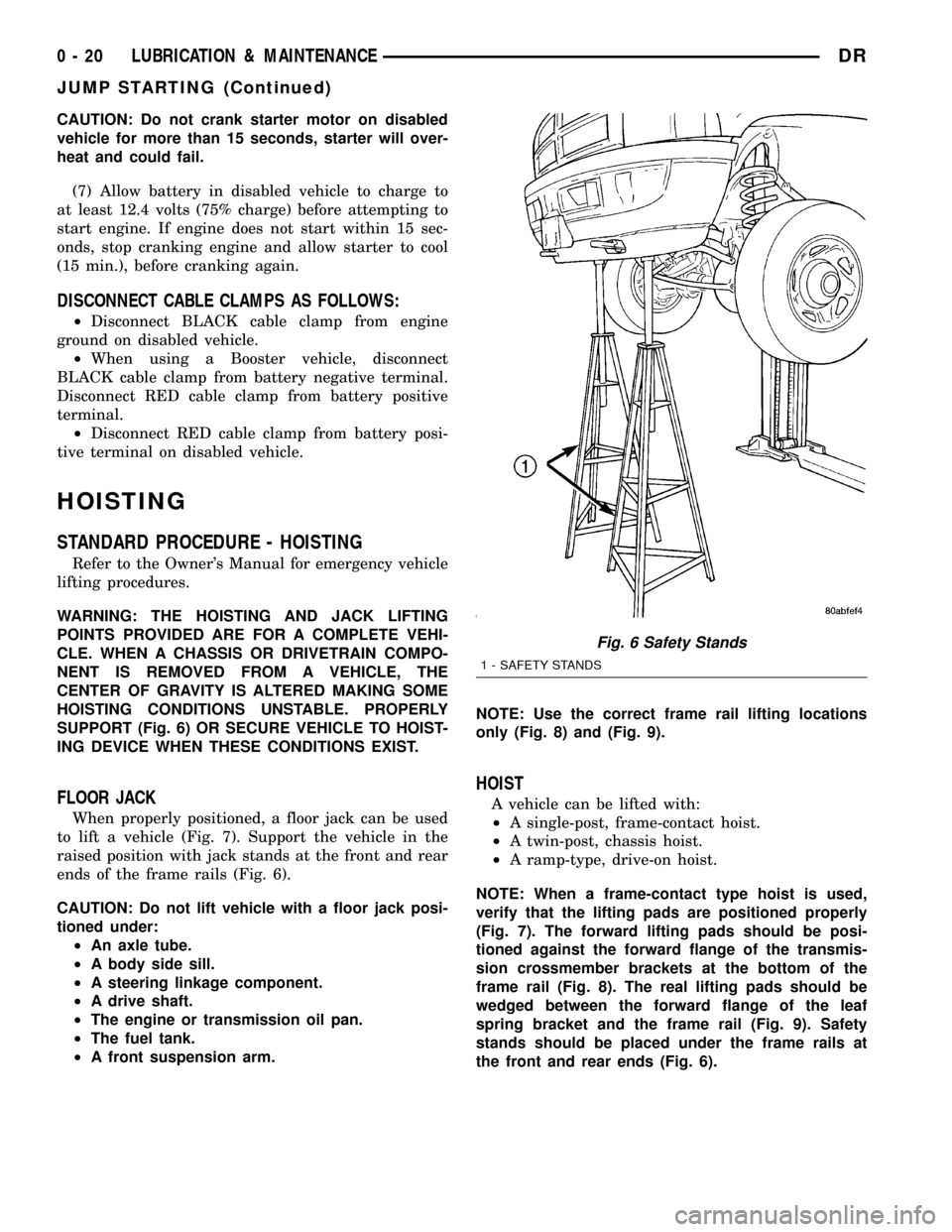
SUPPORT (Fig. 6) OR SECURE VEHICLE TO HOIST-
ING DEVICE WHEN THESE CONDITIONS EXIST.
FLOOR JACK
When properly positioned, a floor jack can be used
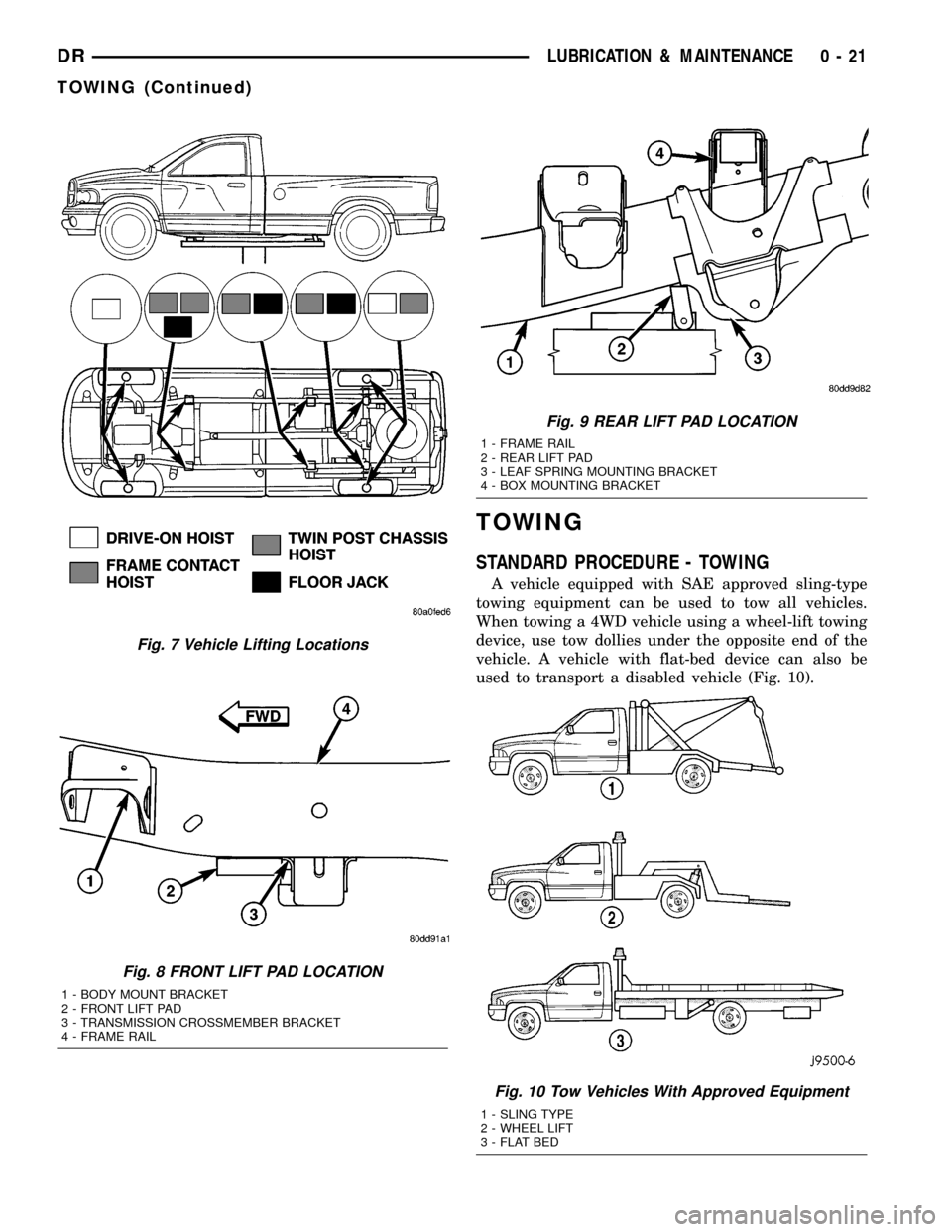
to lift a vehicle (Fig. 7). Support the vehicle in the
raised position with jack stands at the front and rear
ends of the frame rails (Fig. 6).
CAUTION: Do not lift vehicle with a floor jack posi-
tioned under:
²An axle tube.
²A body side sill.
²A steering linkage component.
²A drive shaft.
²The engine or transmission oil pan.
²The fuel tank.
²A front suspension arm.NOTE: Use the correct frame rail lifting locations
only (Fig. 8) and (Fig. 9).
HOIST
A vehicle can be lifted with:
²A single-post, frame-contact hoist.
²A twin-post, chassis hoist.
²A ramp-type, drive-on hoist.
NOTE: When a frame-contact type hoist is used,
verify that the lifting pads are positioned properly
(Fig. 7). The forward lifting pads should be posi-
tioned against the forward flange of the transmis-
sion crossmember brackets at the bottom of the
frame rail (Fig. 8). The real lifting pads should be
wedged between the forward flange of the leaf
spring bracket and the frame rail (Fig. 9). Safety
stands should be placed under the frame rails at
the front and rear ends (Fig. 6).
Fig. 6 Safety Stands
1 - SAFETY STANDS
0 - 20 LUBRICATION & MAINTENANCEDR
JUMP STARTING (Continued)
Page 34 of 2627
TOWING
STANDARD PROCEDURE - TOWING
A vehicle equipped with SAE approved sling-type
towing equipment can be used to tow all vehicles.
When towing a 4WD vehicle using a wheel-lift towing
device, use tow dollies under the opposite end of the
vehicle. A vehicle with flat-bed device can also be
used to transport a disabled vehicle (Fig. 10).
Fig. 7 Vehicle Lifting Locations
Fig. 8 FRONT LIFT PAD LOCATION
1 - BODY MOUNT BRACKET
2 - FRONT LIFT PAD
3 - TRANSMISSION CROSSMEMBER BRACKET
4 - FRAME RAIL
Fig. 9 REAR LIFT PAD LOCATION
1 - FRAME RAIL
2 - REAR LIFT PAD
3 - LEAF SPRING MOUNTING BRACKET
4 - BOX MOUNTING BRACKET
Fig. 10 Tow Vehicles With Approved Equipment
1 - SLING TYPE
2 - WHEEL LIFT
3 - FLAT BED
DRLUBRICATION & MAINTENANCE 0 - 21
TOWING (Continued)
Page 76 of 2627
REAR
TABLE OF CONTENTS
page page
REAR
DESCRIPTION.........................41
DIAGNOSIS AND TESTING - SPRING AND
SHOCK.............................41
SPECIFICATIONS
TORQUE CHART......................42
BUSHINGS
REMOVAL.............................43
INSTALLATION.........................43
JOUNCE BUMPER
REMOVAL.............................43
INSTALLATION.........................43
AUXILIARY SPRING BUMPERS (3500)
REMOVAL.............................43INSTALLATION.........................43
SHOCK
REMOVAL.............................43
INSTALLATION.........................43
SPRING
DESCRIPTION.........................44
OPERATION...........................44
REMOVAL.............................44
INSTALLATION.........................44
SPRING TIP INSERTS
REMOVAL.............................44
INSTALLATION.........................45
REAR
DESCRIPTION
The rear suspension is comprised of:
²Shock Absorbers
²Jounce Bumpers
²Leaf Springs
²Auxiliary Leaf Spring (3500 series)
²Auxiliary Spring Bumpers (3500 series)
²Drive Axle
CAUTION: A vehicle should always be loaded so
the vehicle weight center-line is located immedi-
ately forward of the rear axle. Correct vehicle load-
ing provides proper front tire-to-road contact. This
results in maximum vehicle handling stability and
safety. Incorrect vehicle weight distribution can
cause excessive tire tread wear, spring fatigue or
failure, and erratic steering.
CAUTION: Suspension components with rubber/ure-
thane bushings (except stabilizer bar) should be
tightened with the vehicle at normal ride height. It is
important to have the springs supporting the weight
of the vehicle when the fasteners are torqued. If
springs are not at their normal ride position, vehicle
ride comfort could be affected and premature bush-
ing wear may occur.
DIAGNOSIS AND TESTING - SPRING AND
SHOCK
A knocking or rattling noise from a shock absorber
may be caused by movement between mounting
bushings and metal brackets or attaching compo-
nents. These noises can usually be stopped by tight-
ening the attaching nuts. If the noise persists,
inspect for damaged and worn bushings, and attach-
ing components. Repair as necessary if any of these
conditions exist.
A squeaking noise from the shock absorber may be
caused by the hydraulic valving and may be intermit-
tent. This condition is not repairable and the shock
absorber must be replaced.
The shock absorbers are not refillable or adjust-
able. If a malfunction occurs, the shock absorber
must be replaced. To test a shock absorber, hold it in
an upright position and force the piston in and out of
the cylinder four or five times. The action throughout
each stroke should be smooth and even.
The spring eye and shock absorber bushings do not
require any type of lubrication. Do not attempt to
stop spring bushing noise by lubricating them.
Grease and mineral oil-base lubricants will deterio-
rate the bushing rubber.
If the vehicle is used for severe, off-road operation,
the springs should be examined periodically. Check
for broken and shifted leafs, loose and missing clips,
and broken center bolts. Refer to Spring and Shock
Absorber Diagnosis chart for additional information.
DRREAR 2 - 41
Page 77 of 2627
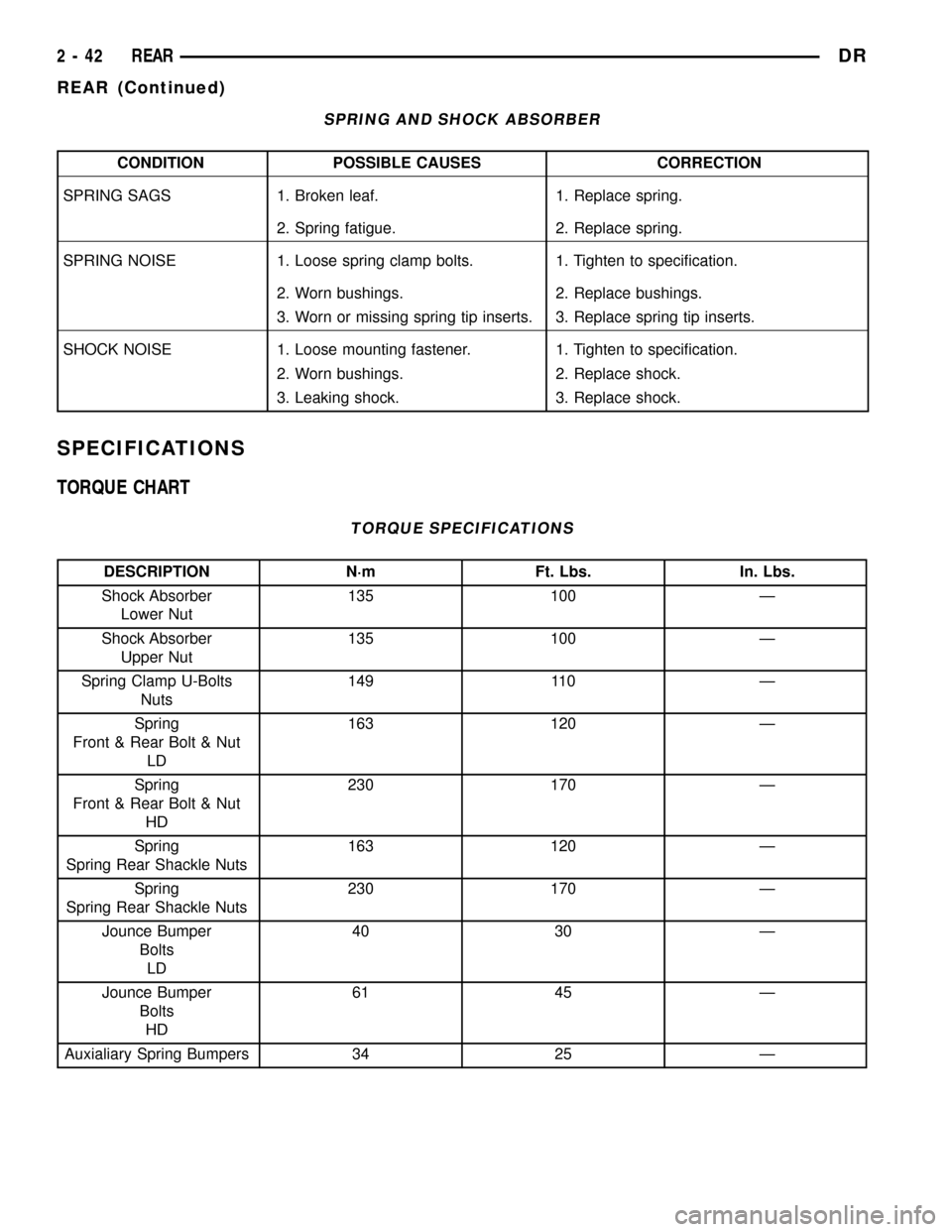
SPRING AND SHOCK ABSORBER
CONDITION POSSIBLE CAUSES CORRECTION
SPRING SAGS 1. Broken leaf. 1. Replace spring.
2. Spring fatigue. 2. Replace spring.
SPRING NOISE 1. Loose spring clamp bolts. 1. Tighten to specification.
2. Worn bushings. 2. Replace bushings.
3. Worn or missing spring tip inserts. 3. Replace spring tip inserts.
SHOCK NOISE 1. Loose mounting fastener. 1. Tighten to specification.
2. Worn bushings. 2. Replace shock.
3. Leaking shock. 3. Replace shock.
SPECIFICATIONS
TORQUE CHART
TORQUE SPECIFICATIONS
DESCRIPTION N´m Ft. Lbs. In. Lbs.
Shock Absorber
Lower Nut135 100 Ð
Shock Absorber
Upper Nut135 100 Ð
Spring Clamp U-Bolts
Nuts149 110 Ð
Spring
Front & Rear Bolt & Nut
LD163 120 Ð
Spring
Front & Rear Bolt & Nut
HD230 170 Ð
Spring
Spring Rear Shackle Nuts163 120 Ð
Spring
Spring Rear Shackle Nuts230 170 Ð
Jounce Bumper
Bolts
LD40 30 Ð
Jounce Bumper
Bolts
HD61 45 Ð
Auxialiary Spring Bumpers 34 25 Ð
2 - 42 REARDR
REAR (Continued)
Page 79 of 2627
(3) Tighten the upper and lower bolt/nuts Tighten
to 135 N.m (100 ft. lbs.)
(4) Remove the support and lower the vehicle.
SPRING
DESCRIPTION
The rear suspension system uses a multi-leaf
springs and a solid drive axle. The forward end of the
springs are mounted to the body rail hangers
through rubber bushings. The rearward end of the
springs are attached to the body by the use of shack-
les. The spring and shackles use rubber bushings.
OPERATION
The springs control ride quality and maintain vehi-
cle ride height. The shackles allow the springs to
change their length as the vehicle moves over various
road conditions.
REMOVAL
(1) Raise and support the vehicle.
(2) Support the axle with a suitable holding fix-
ture.
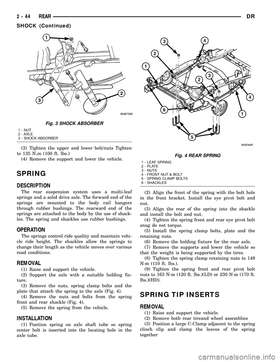
(3) Remove the nuts, spring clamp bolts and the
plate that attach the spring to the axle (Fig. 4).
(4) Remove the nuts and bolts from the spring
front and rear shackle (Fig. 4).
(5) Remove the spring from the vehicle.
INSTALLATION
(1) Position spring on axle shaft tube so spring
center bolt is inserted into the locating hole in the
axle tube.(2) Align the front of the spring with the bolt hole
in the front bracket. Install the eye pivot bolt and
nut.
(3) Align the rear of the spring into the shackle
and install the bolt and nut.
(4) Tighten the spring front and rear eye pivot bolt
snug do not torque.
(5) Install the spring clamp bolts, plate and the
retaining nuts.
(6) Remove the holding fixture for the rear axle.
(7) Remove the supports and lower the vehicle so
that the weight is being supported by the tires.
(8) Tighten the spring clamp retaining nuts to 149
N´m (110 ft. lbs.).
(9) Tighten the spring front and rear pivot bolt
nuts to 163 N´m (120 ft. lbs.)(LD) or 230 N´m (170 ft.
lbs.)(HD).
SPRING TIP INSERTS
REMOVAL
(1) Raise and support the vehicle.
(2) Remove both rear tireand wheel assemblies
(3) Position a large C-Clamp adjacent to the spring
clinch clip and clamp the leaves of the spring
together
Fig. 3 SHOCK ABSORBER
1 - NUT
2 - AXLE
3 - SHOCK ABSORBER
Fig. 4 REAR SPRING
1 - LEAF SPRING
2 - PLATE
3 - NUTS
4 - FRONT NUT & BOLT
5 - SPRING CLAMP BOLTS
6 - SHACKLES
2 - 44 REARDR
SHOCK (Continued)
Page 80 of 2627
CAUTION: When working on the front leaf spring
clinch clamps finish the front before starting on the
rear to prevent personal injury.
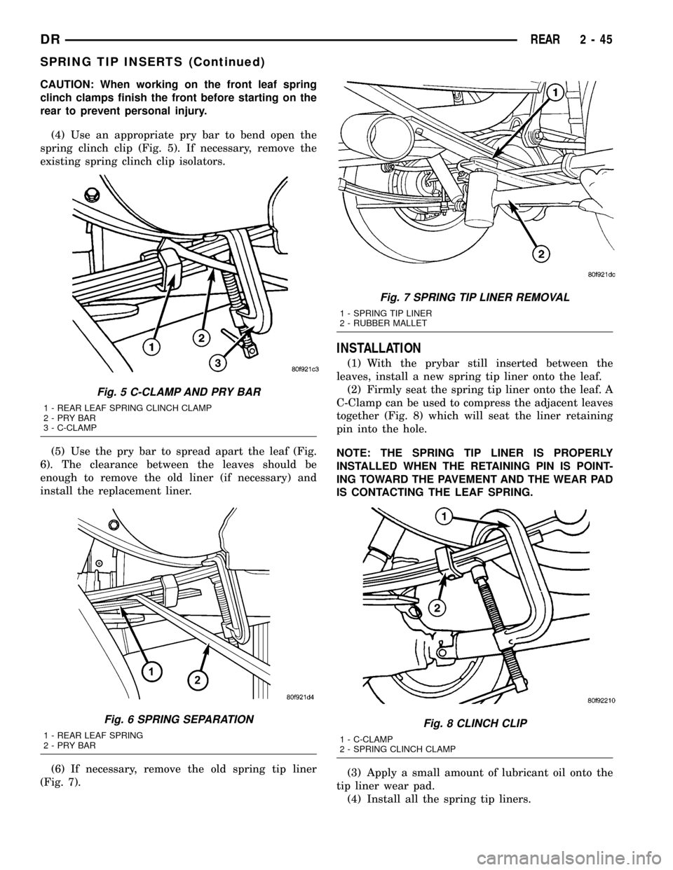
(4) Use an appropriate pry bar to bend open the
spring clinch clip (Fig. 5). If necessary, remove the
existing spring clinch clip isolators.
(5) Use the pry bar to spread apart the leaf (Fig.
6). The clearance between the leaves should be
enough to remove the old liner (if necessary) and
install the replacement liner.
(6) If necessary, remove the old spring tip liner
(Fig. 7).
INSTALLATION
(1) With the prybar still inserted between the
leaves, install a new spring tip liner onto the leaf.
(2) Firmly seat the spring tip liner onto the leaf. A
C-Clamp can be used to compress the adjacent leaves
together (Fig. 8) which will seat the liner retaining
pin into the hole.
NOTE: THE SPRING TIP LINER IS PROPERLY
INSTALLED WHEN THE RETAINING PIN IS POINT-
ING TOWARD THE PAVEMENT AND THE WEAR PAD
IS CONTACTING THE LEAF SPRING.
(3) Apply a small amount of lubricant oil onto the
tip liner wear pad.
(4) Install all the spring tip liners.
Fig. 5 C-CLAMP AND PRY BAR
1 - REAR LEAF SPRING CLINCH CLAMP
2-PRYBAR
3 - C-CLAMP
Fig. 6 SPRING SEPARATION
1 - REAR LEAF SPRING
2-PRYBAR
Fig. 7 SPRING TIP LINER REMOVAL
1 - SPRING TIP LINER
2 - RUBBER MALLET
Fig. 8 CLINCH CLIP
1 - C-CLAMP
2 - SPRING CLINCH CLAMP
DRREAR 2 - 45
SPRING TIP INSERTS (Continued)
Page 81 of 2627
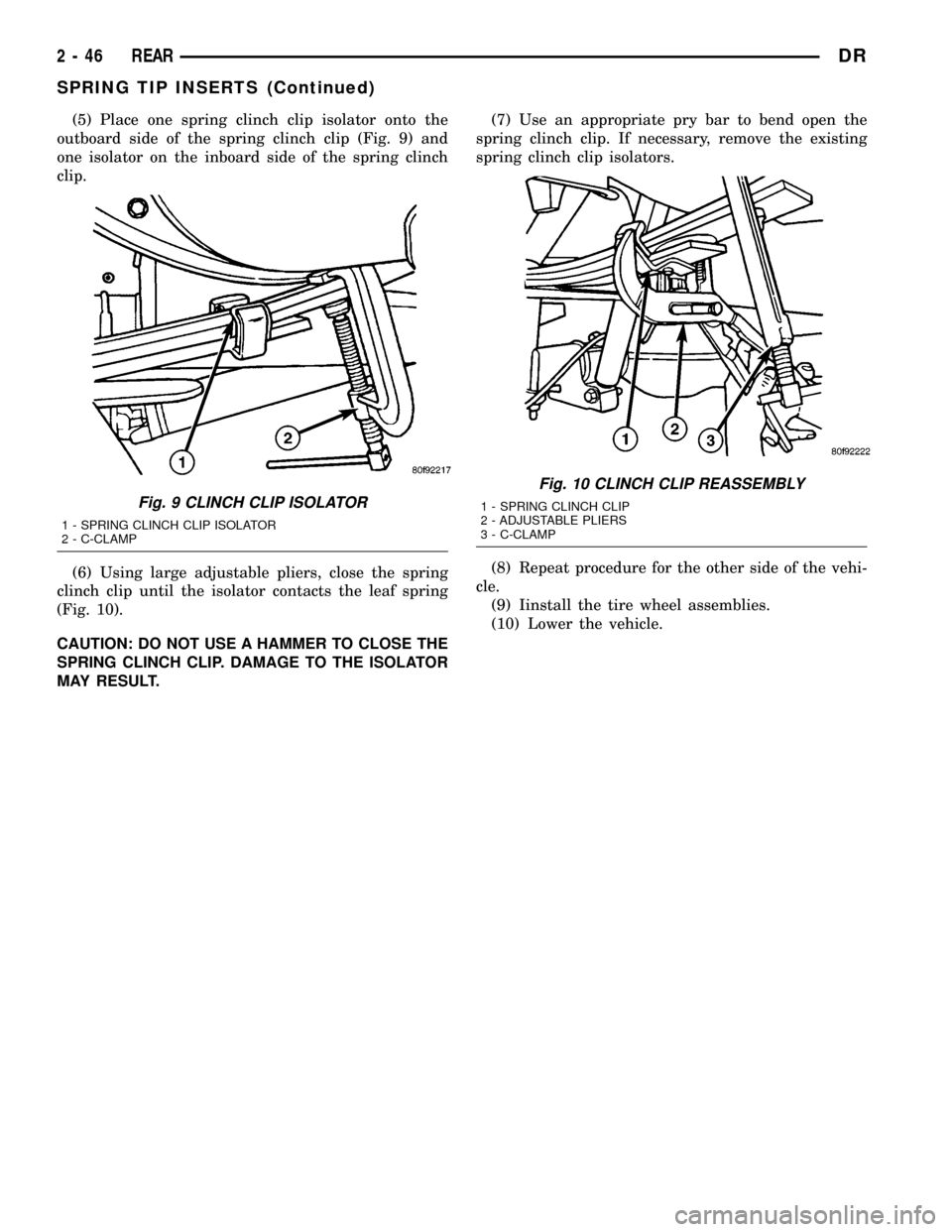
(5) Place one spring clinch clip isolator onto the
outboard side of the spring clinch clip (Fig. 9) and
one isolator on the inboard side of the spring clinch
clip.
(6) Using large adjustable pliers, close the spring
clinch clip until the isolator contacts the leaf spring
(Fig. 10).
CAUTION: DO NOT USE A HAMMER TO CLOSE THE
SPRING CLINCH CLIP. DAMAGE TO THE ISOLATOR
MAY RESULT.(7) Use an appropriate pry bar to bend open the
spring clinch clip. If necessary, remove the existing
spring clinch clip isolators.
(8) Repeat procedure for the other side of the vehi-
cle.
(9) Iinstall the tire wheel assemblies.
(10) Lower the vehicle.
Fig. 9 CLINCH CLIP ISOLATOR
1 - SPRING CLINCH CLIP ISOLATOR
2 - C-CLAMP
Fig. 10 CLINCH CLIP REASSEMBLY
1 - SPRING CLINCH CLIP
2 - ADJUSTABLE PLIERS
3 - C-CLAMP
2 - 46 REARDR
SPRING TIP INSERTS (Continued)
Page 164 of 2627
Condition Possible Causes Correction
Gear Teeth Broke 1. Overloading. 1. Replace gears. Examine other
gears and bearings for possible
damage.
2. Erratic clutch operation. 2. Replace gears and examine the
remaining parts for damage. Avoid
erratic clutch operation.
3. Ice-spotted pavement. 3. Replace gears and examine
remaining parts for damage.
4. Improper adjustments. 4. Replace gears and examine
remaining parts for damage. Ensure
ring gear backlash is correct.
Axle Noise 1. Insufficient lubricant. 1. Fill differential with the correct
fluid type and quantity.
2. Improper ring gear and pinion
adjustment.2. Check ring gear and pinion
contact pattern. Adjust backlash or
pinion depth.
3. Unmatched ring gear and pinion. 3. Replace gears with a matched
ring gear and pinion.
4. Worn teeth on ring gear and/or
pinion.4. Replace ring gear and pinion.
5. Loose pinion bearings. 5. Adjust pinion bearing pre-load.
6. Loose differential bearings. 6. Adjust differential bearing
pre-load.
7. Mis-aligned or sprung ring gear. 7. Measure ring gear run-out.
Replace components as necessary.
8. Loose differential bearing cap
bolts.8. Inspect differential components
and replace as necessary. Ensure
that the bearing caps are torqued
tot he proper specification.
9. Housing not machined properly. 9. Replace housing.
REMOVAL
(1) Raise and support the vehicle.
(2) Position a lift under axle and secure axle to
lift.
(3) Remove wheels and tires assemblies.
(4) Remove all brake components.
(5) Remove axle vent hose.
(6) Mark propeller shaft and companion flange for
installation alignment reference.
(7) Remove propeller shaft.
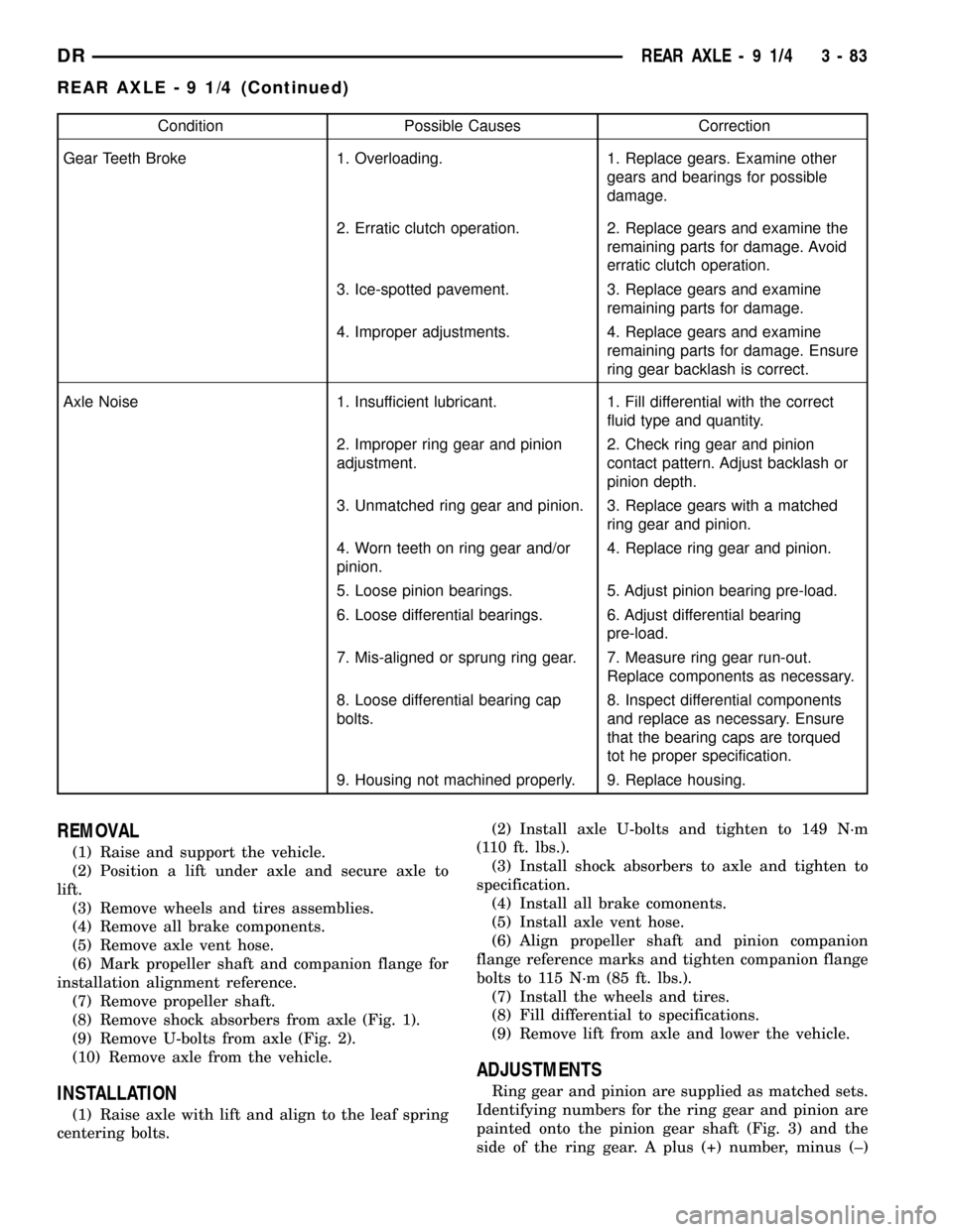
(8) Remove shock absorbers from axle (Fig. 1).
(9) Remove U-bolts from axle (Fig. 2).
(10) Remove axle from the vehicle.
INSTALLATION
(1) Raise axle with lift and align to the leaf spring
centering bolts.(2) Install axle U-bolts and tighten to 149 N´m
(110 ft. lbs.).
(3) Install shock absorbers to axle and tighten to
specification.
(4) Install all brake comonents.
(5) Install axle vent hose.
(6) Align propeller shaft and pinion companion
flange reference marks and tighten companion flange
bolts to 115 N´m (85 ft. lbs.).
(7) Install the wheels and tires.
(8) Fill differential to specifications.
(9) Remove lift from axle and lower the vehicle.
ADJUSTMENTS
Ring gear and pinion are supplied as matched sets.
Identifying numbers for the ring gear and pinion are
painted onto the pinion gear shaft (Fig. 3) and the
side of the ring gear. A plus (+) number, minus (±)
DRREAR AXLE - 9 1/4 3 - 83
REAR AXLE - 9 1/4 (Continued)
Page 165 of 2627
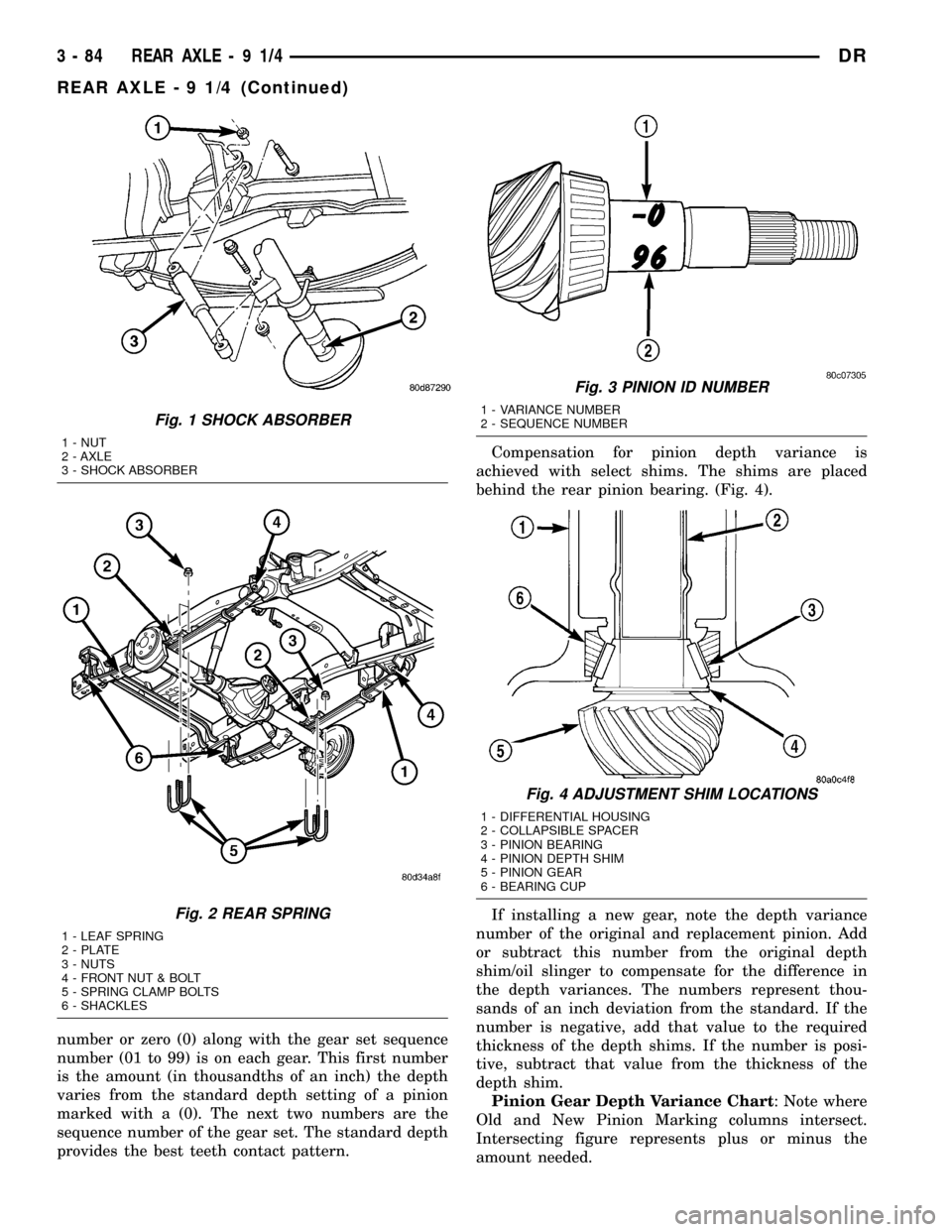
number or zero (0) along with the gear set sequence
number (01 to 99) is on each gear. This first number
is the amount (in thousandths of an inch) the depth
varies from the standard depth setting of a pinion
marked with a (0). The next two numbers are the
sequence number of the gear set. The standard depth
provides the best teeth contact pattern.Compensation for pinion depth variance is
achieved with select shims. The shims are placed
behind the rear pinion bearing. (Fig. 4).
If installing a new gear, note the depth variance
number of the original and replacement pinion. Add
or subtract this number from the original depth
shim/oil slinger to compensate for the difference in
the depth variances. The numbers represent thou-
sands of an inch deviation from the standard. If the
number is negative, add that value to the required
thickness of the depth shims. If the number is posi-
tive, subtract that value from the thickness of the
depth shim.
Pinion Gear Depth Variance Chart: Note where
Old and New Pinion Marking columns intersect.
Intersecting figure represents plus or minus the
amount needed.
Fig. 1 SHOCK ABSORBER
1 - NUT
2 - AXLE
3 - SHOCK ABSORBER
Fig. 2 REAR SPRING
1 - LEAF SPRING
2 - PLATE
3 - NUTS
4 - FRONT NUT & BOLT
5 - SPRING CLAMP BOLTS
6 - SHACKLES
Fig. 3 PINION ID NUMBER
1 - VARIANCE NUMBER
2 - SEQUENCE NUMBER
Fig. 4 ADJUSTMENT SHIM LOCATIONS
1 - DIFFERENTIAL HOUSING
2 - COLLAPSIBLE SPACER
3 - PINION BEARING
4 - PINION DEPTH SHIM
5 - PINION GEAR
6 - BEARING CUP
3 - 84 REAR AXLE-91/4DR
REAR AXLE - 9 1/4 (Continued)
Page 196 of 2627
Condition Possible Causes Correction
Axle Noise 1. Insufficient lubricant. 1. Fill differential with the correct fluid
type and quantity.
2. Improper ring gear and pinion
adjustment.2. Check ring gear and pinion contact
pattern. Adjust backlash or pinion
depth.
3. Unmatched ring gear and pinion. 3. Replace gears with a matched ring
gear and pinion.
4. Worn teeth on ring gear and/or
pinion.4. Replace ring gear and pinion.
5. Loose pinion bearings. 5. Adjust pinion bearing pre-load.
6. Loose differential bearings. 6. Adjust differential bearing pre-load.
7. Mis-aligned or sprung ring gear. 7. Measure ring gear run-out. Replace
components as necessary.
8. Loose differential bearing cap
bolts.8. Inspect differential components and
replace as necessary. Ensure that the
bearing caps are torqued tot he
proper specification.
9. Housing not machined properly. 9. Replace housing.
REMOVAL
(1) Raise and support the vehicle.
(2) Position a lift under axle and secure lift to the
axle.
(3) Remove wheels and tires assemblies.
(4) Remove all brake components.
(5) Mark propeller shaft and companion flange for
installation alignment reference.
(6) Remove propeller shaft.
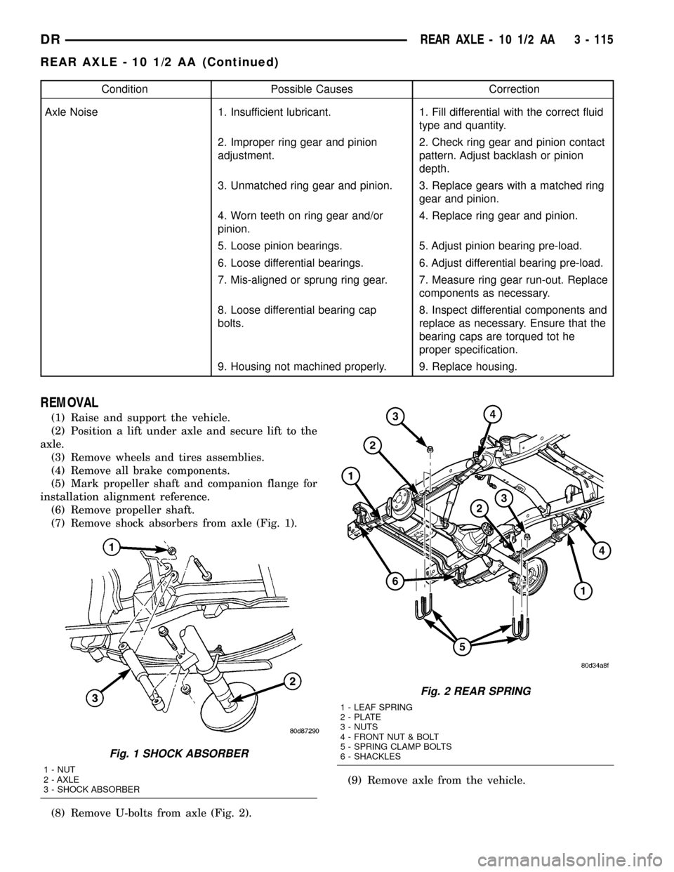
(7) Remove shock absorbers from axle (Fig. 1).
(8) Remove U-bolts from axle (Fig. 2).(9) Remove axle from the vehicle.
Fig. 1 SHOCK ABSORBER
1 - NUT
2 - AXLE
3 - SHOCK ABSORBER
Fig. 2 REAR SPRING
1 - LEAF SPRING
2 - PLATE
3 - NUTS
4 - FRONT NUT & BOLT
5 - SPRING CLAMP BOLTS
6 - SHACKLES
DRREAR AXLE - 10 1/2 AA 3 - 115
REAR AXLE - 10 1/2 AA (Continued)