Transmission lines DODGE RAM 1500 1998 2.G Workshop Manual
[x] Cancel search | Manufacturer: DODGE, Model Year: 1998, Model line: RAM 1500, Model: DODGE RAM 1500 1998 2.GPages: 2627
Page 4 of 2627

BODY CODE PLATE
DESCRIPTION
The Body Code Plate (Fig. 4) is located on the right
front hydroform fender rail just behind the headlight
assembly (Fig. 3). There are seven lines of informa-
tion on the body code plate. Lines 5, 6, and 7 are not
used to define service information. Information reads
from left to right, starting with line 4 in the center of
the plate to line 1 at the bottom of the plate.
The last code imprinted on a vehicle code plate will
be followed by the imprinted word END. When two
vehicle code plates are required, the last available
spaces on the first plate will be imprinted with the
letters CTD (for continued).
When a second vehicle code plate is necessary, the
first four spaces on each row will not be used because
of the plate overlap.
BODY CODE PLATEÐLINE 4
DIGITS 1 THROUGH 12
Vehicle Order Number
DIGITS 13, 14, AND 15
Transmission Codes
²DG4 = 4±speed Automatic (45RFE)
²DG8 = 4±speed Automatic (48RE)²DDC = 5±speed Manual (NV3500)
²DDP = 5±speed Manual (NV4500)
²DEC = 6±speed Manual (NV5600)
²DEE = 6±speed Manual Tremec (T-56)
DIGITS 16, 17, AND 18
Car Line Shell
²DR1=15004X2
²DR6=15004X4
²DR2=25004X2
²DR7=25004X4
²DR3=35004X2
²DR8=35004X4
DIGIT 19
Price Class
²L = Low
²H = Highline
DIGITS 20 AND 21
Body Type
²41 = Ram Truck Quad Cab, Short Box
²42 = Ram Truck Quad Cab, Long Box
²61 = Ram Truck Standard Cab, Short Box
²62 = Ram Truck Standard Cab, Long Box
Fig. 3 BODY CODE PLATE LOCATION
1 - FENDER
2 - RADIATOR CROSSMEMBER
3 - HYDROFORM FENDER RAIL
4 - RIVOT (2)
5 - BODY CODE PLATE
Fig. 4 BODY CODE PLATE
1 - PRIMARY PAINT
2 - SECONDARY PAINT
3 - TRANSMISSION CODE
4 - VEHICLE MODEL NUMBER
5 - ENGINE CODE
6 - INTERIOR TRIM CODE
7 - VEHICLE IDENTIFICATION NUMBER
8 - TAILGATE CODE
9 - CARGO BOX CODE
10 - TAILGATE TRIM CODE
11 - BODY-IN-WHITE SEQUENCE
12 - MARKET CODE
13 - SPECIES CODE
14 - PAINT PROCEDURE
15 - VEHICLE ORDER NUMBER
DRINTRODUCTION 3
Page 18 of 2627
FLUID ADDITIVES
DaimlerChrysler strongly recommends against the
addition of any fluids to the transmission, other than
those automatic transmission fluids listed above.
Exceptions to this policy are the use of special dyes
to aid in detecting fluid leaks.
Various ªspecialº additives and supplements exist
that claim to improve shift feel and/or quality. These
additives and others also claim to improve converter
clutch operation and inhibit overheating, oxidation,
varnish, and sludge. These claims have not been sup-
ported to the satisfaction of DaimlerChrysler and
these additivesmust not be used.The use of trans-
mission ªsealersº should also be avoided, since they
may adversely affect the integrity of transmission
seals.
OPERATION - AUTOMATIC TRANSMISSION
FLUID
The automatic transmission fluid is selected based
upon several qualities. The fluid must provide a high
level of protection for the internal components by
providing a lubricating film between adjacent metal
components. The fluid must also be thermally stable
so that it can maintain a consistent viscosity through
a large temperature range. If the viscosity stays con-
stant through the temperature range of operation,
transmission operation and shift feel will remain con-
sistent. Transmission fluid must also be a good con-
ductor of heat. The fluid must absorb heat from the
internal transmission components and transfer that
heat to the transmission case.
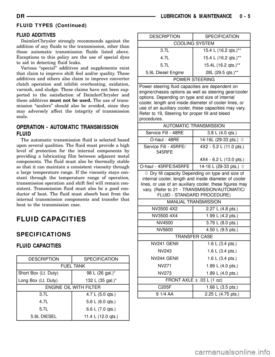
FLUID CAPACITIES
SPECIFICATIONS
FLUID CAPACITIES
DESCRIPTION SPECIFICATION
FUEL TANK
Short Box (Lt. Duty) 98 L (26 gal.)*
Long Box (Lt. Duty) 132 L (35 gal.)*
ENGINE OIL WITH FILTER
3.7L 4.7 L (5.0 qts.)
4.7L 5.6 L (6.0 qts.)
5.7L 6.6 L (7.0 qts.)
5.9L DIESEL 11.4 L (12.0 qts.)
DESCRIPTION SPECIFICATION
COOLING SYSTEM
3.7L 15.4 L (16.2 qts.)**
4.7L 15.4 L (16.2 qts.)**
5.7L 15.4L (16.2 qts.)**
5.9L Diesel Engine 28L (29.5 qts.)**
POWER STEERING
Power steering fluid capacities are dependent on
engine/chassis options as well as steering gear/cooler
options. Depending on type and size of internal
cooler, length and inside diameter of cooler lines, or
use of an auxiliary cooler, these capacities may vary.
Refer to 19, Steering for proper fill and bleed
procedures.
AUTOMATIC TRANSMISSION
Service Fill - 48RE 3.8 L (4.0 qts.)
O-haul - 48RE 14-16L (29-33 pts.)L
Service Fill - 45RFE/
545RFE4X2 - 5.2 L (11.0 pts.)
4X4 - 6.2 L (13.0 pts.)
O-haul - 45RFE/545RFE 14-16 L (29-33 pts.)L
LDry fill capacity Depending on type and size of
internal cooler, length and inside diameter of cooler
lines, or use of an auxiliary cooler, these figures may
vary. (Refer to 21 - TRANSMISSION/AUTOMATIC/
FLUID - STANDARD PROCEDURE)
MANUAL TRANSMISSION
NV3500 4X2 2.27 L (4.8 pts.)
NV3500 4X4 1.99 L (4.2 pts.)
NV4500 3.79 L (8.0 pts.)
NV5600 4.50 L (9.5 pts.)
TRANSFER CASE
NV241 GENII 1.6 L (3.4 pts.)
NV243 1.6 L (3.4 pts.)
NV244 GENII 1.6 L (3.4 pts.)
NV271 1.89 L (4.0 pts.)
NV273 1.89 L (4.0 pts.)
FRONT AXLE .03 L (1 oz)
C205F 1.66 L (3.5 pts.)
9 1/4 AA 2.25 L (4.75 pts.)
DRLUBRICATION & MAINTENANCE 0 - 5
FLUID TYPES (Continued)
Page 252 of 2627

normal and should not be mistaken for contam-
ination.
(a) If fluid level is abnormally low, look for evi-
dence of leaks at calipers, wheel cylinders, brake
lines, and master cylinder.
(b) If fluid appears contaminated, drain out a
sample to examine. System will have to be flushed
if fluid is separated into layers, or contains a sub-
stance other than brake fluid. The system seals
and cups will also have to be replaced after flush-
ing. Use clean brake fluid to flush the system.
(4) Check parking brake operation. Verify free
movement and full release of cables and pedal. Also
note if vehicle was being operated with parking
brake partially applied.
(5) Check brake pedal operation. Verify that pedal
does not bind and has adequate free play. If pedal
lacks free play, check pedal and power booster for
being loose or for bind condition. Do not road test
until condition is corrected.
(6) Check booster vacuum check valve and hose.
(7) If components checked appear OK, road test
the vehicle.
ROAD TESTING
(1) If complaint involved low brake pedal, pump
pedal and note if it comes back up to normal height.
(2) Check brake pedal response with transmission
in Neutral and engine running. Pedal should remain
firm under constant foot pressure.
(3) During road test, make normal and firm brake
stops in 25-40 mph range. Note faulty brake opera-
tion such as low pedal, hard pedal, fade, pedal pulsa-
tion, pull, grab, drag, noise, etc.
(4) Attempt to stop the vehicle with the parking
brake only and note grab, drag, noise, etc.
PEDAL FALLS AWAY
A brake pedal that falls away under steady foot
pressure is generally the result of a system leak or
fluid contamination. The leak point could be at a
brake line, fitting, hose, or caliper/wheel cylinder. If
leakage is severe, fluid will be evident at or around
the leaking component.
Internal leakage (seal by-pass) in the master cylin-
der caused by worn or damaged piston cups, may
also be the problem cause.
An internal leak in the ABS or RWAL system may
also be the problem with no physical evidence.
LOW PEDAL
If a low pedal is experienced, pump the pedal sev-
eral times. If the pedal comes back up worn linings,
rotors, drums, or rear brakes out of adjustment are
the most likely causes. The proper course of action isto inspect and replace all worn component and make
the proper adjustments.
SPONGY PEDAL
A spongy pedal is most often caused by air in the
system. However, thin brake drums or substandard
brake lines and hoses can also cause a spongy pedal.
The proper course of action is to bleed the system,
and replace thin drums and substandard quality
brake hoses if suspected.
HARD PEDAL OR HIGH PEDAL EFFORT
A hard pedal or high pedal effort may be due to
lining that is water soaked, contaminated, glazed, or
badly worn. The power booster or check valve or a
vacuum hose could also be faulty.
PEDAL PULSATION
Pedal pulsation is caused by components that are
loose, or beyond tolerance limits.
The primary cause of pulsation are disc brake
rotors with excessive lateral runout or thickness vari-
ation, or out of round brake drums. Other causes are
loose wheel bearings or calipers and worn, damaged
tires.
NOTE: Some pedal pulsation may be felt during
ABS activation.
BRAKE DRAG
Brake drag occurs when the lining is in constant
contact with the rotor or drum. Drag can occur at one
wheel, all wheels, fronts only, or rears only.
Drag is a product of incomplete brake shoe release.
Drag can be minor or severe enough to overheat the
linings, rotors and drums.
Minor drag will usually cause slight surface char-
ring of the lining. It can also generate hard spots in
rotors and drums from the overheat-cool down pro-
cess. In most cases, the rotors, drums, wheels and
tires are quite warm to the touch after the vehicle is
stopped.
Severe drag can char the brake lining all the way
through. It can also distort and score rotors and
drums to the point of replacement. The wheels, tires
and brake components will be extremely hot. In
severe cases, the lining may generate smoke as it
chars from overheating.
Common causes of brake drag are:
²Seized or improperly adjusted parking brake
cables.
²Loose/worn wheel bearing.
²Seized caliper or wheel cylinder piston.
²Caliper binding on corroded bushings or rusted
slide surfaces.
²Loose caliper mounting.
DRBRAKES - BASE 5 - 3
BRAKES - BASE (Continued)
Page 281 of 2627

INSTALLATION
(1) Install the hydraulic booster and tighten the
mounting nuts to 28 N´m (21 ft. lbs.).
(2) Install the booster push rod, washer and clip
onto the brake pedal.
(3) Install the master cylinder on the mounting
studs. and tighten the mounting nuts to 23 N´m (17
ft. lbs.).
(4) Install the brake lines to the master cylinder
and tighten to 19-200 N´m (170-200 in. lbs.).
(5) Install the hydraulic booster line bracket onto
the master cylinder mounting studs.
(6) Install the master cylinder mounting nuts and
tighten to 23 N´m (17 ft. lbs.).
(7) Install the hydraulic booster pressure lines to
the bracket and booster.
(8) Tighten the pressure lines to 41 N´m (30 ft.
lbs.).
NOTE: Inspect o-rings on the pressure line fittings
to insure they are in good condition before installa-
tion. Replace o-rings if necessary.
(9) Install the return hose to the booster.
(10) Bleed base brake system, (Refer to 5 -
BRAKES/HYDRAULIC/MECHANICAL - STAN-
DARD PROCEDURE).
(11) Fill the power steering pump with fluid,
(Refer to 19 - STEERING/PUMP - STANDARD PRO-
CEDURE).
CAUTION: MOPAR (MS-9602) ATF+4 is to be used in
the power steering system. No other power steering
or automatic transmission fluid is to be used in thesystem. Damage may result to the power steering
pump and system if any other fluid is used, and do
not overfill.
(12) Bleed the hydraulic booster (Refer to 5 -
BRAKES/HYDRAULIC/MECHANICAL/POWER
BRAKE BOOSTER - STANDARD PROCEDURE).
ROTORS
DIAGNOSIS AND TESTING
DISC BRAKE ROTOR
The rotor braking surfaces should not be refinished
unless necessary.
Light surface rust and scale can be removed with a
lathe equipped with dual sanding discs. The rotor
surfaces can be restored by machining with a disc
brake lathe if surface scoring and wear are light.
Replace the rotor for the following conditions:
²Severely Scored
²Tapered
²Hard Spots
²Cracked
²Below Minimum Thickness
ROTOR MINIMUM THICKNESS
Measure rotor thickness at the center of the brake
shoe contact surface. Replace the rotor if below min-
imum thickness, or if machining would reduce thick-
ness below the allowable minimum.
Rotor minimum thickness is usually specified on
the rotor hub. The specification is either stamped or
cast into the hub surface.
ROTOR RUNOUT
Check rotor lateral runout with dial indicator
C-3339 (Fig. 56). Excessive lateral runout will cause
brake pedal pulsation and rapid, uneven wear of the
brake shoes. Position the dial indicator plunger
approximately 25.4 mm (1 in.) inward from the rotor
edge.
NOTE: Be sure wheel bearing has zero end play
before checking rotor runout.
Maximum allowable rotor runout is 0.127 mm
(0.005 in.).
ROTOR THICKNESS VARIATION
Variations in rotor thickness will cause pedal pul-
sation, noise and shudder.
Measure rotor thickness at 6 to 12 points around
the rotor face (Fig. 57).
Fig. 55 HYDRO-BOOST UNIT
1 - INLET HOSE
2 - HYDRO-BOOST UNIT
3 - MASTER CYLINDER UNIT
4 - RETURN HOSE
5 - OUTLET HOSE
5 - 32 BRAKES - BASEDR
HYDRO-BOOST BRAKE BOOSTER (Continued)
Page 304 of 2627
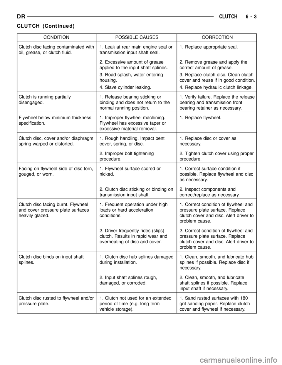
CONDITION POSSIBLE CAUSES CORRECTION
Clutch disc facing contaminated with
oil, grease, or clutch fluid.1. Leak at rear main engine seal or
transmission input shaft seal.1. Replace appropriate seal.
2. Excessive amount of grease
applied to the input shaft splines.2. Remove grease and apply the
correct amount of grease.
3. Road splash, water entering
housing.3. Replace clutch disc. Clean clutch
cover and reuse if in good condition.
4. Slave cylinder leaking. 4. Replace hydraulic clutch linkage.
Clutch is running partially
disengaged.1. Release bearing sticking or
binding and does not return to the
normal running position.1. Verify failure. Replace the release
bearing and transmission front
bearing retainer as necessary.
Flywheel below minimum thickness
specification.1. Improper flywheel machining.
Flywheel has excessive taper or
excessive material removal.1. Replace flywheel.
Clutch disc, cover and/or diaphragm
spring warped or distorted.1. Rough handling. Impact bent
cover, spring, or disc.1. Replace disc or cover as
necessary.
2. Improper bolt tightening
procedure.2. Tighten clutch cover using proper
procedure.
Facing on flywheel side of disc torn,
gouged, or worn.1. Flywheel surface scored or
nicked.1. Correct surface condition if
possible. Replace flywheel and disc
as necessary.
2. Clutch disc sticking or binding on
transmission input shaft.2. Inspect components and
correct/replace as necessary.
Clutch disc facing burnt. Flywheel
and cover pressure plate surfaces
heavily glazed.1. Frequent operation under high
loads or hard acceleration
conditions.1. Correct condition of flywheel and
pressure plate surface. Replace
clutch cover and disc. Alert driver to
problem cause.
2. Driver frequently rides (slips)
clutch. Results in rapid wear and
overheating of disc and cover.2. Correct condition of flywheel and
pressure plate surface. Replace
clutch cover and disc. Alert driver to
problem cause.
Clutch disc binds on input shaft
splines.1. Clutch disc hub splines damaged
during installation.1. Clean, smooth, and lubricate hub
splines if possible. Replace disc if
necessary.
2. Input shaft splines rough,
damaged, or corroded.2. Clean, smooth, and lubricate
shaft splines if possible. Replace
input shaft if necessary.
Clutch disc rusted to flywheel and/or
pressure plate.1. Clutch not used for an extended
period of time (e.g. long term
vehicle storage).1. Sand rusted surfaces with 180
grit sanding paper. Replace clutch
cover and flywheel if necessary.
DRCLUTCH 6 - 3
CLUTCH (Continued)
Page 307 of 2627
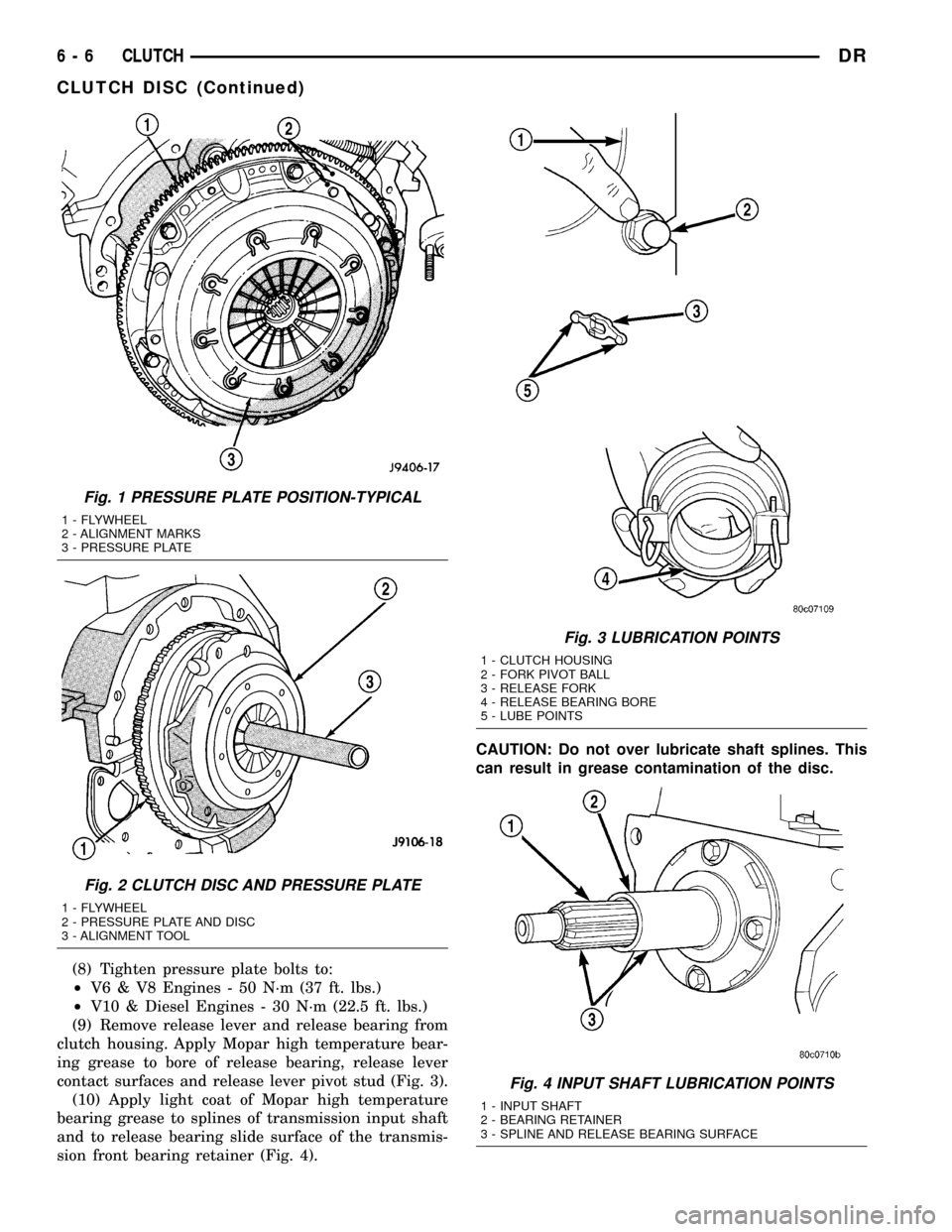
(8) Tighten pressure plate bolts to:
²V6 & V8 Engines - 50 N´m (37 ft. lbs.)
²V10 & Diesel Engines - 30 N´m (22.5 ft. lbs.)
(9) Remove release lever and release bearing from
clutch housing. Apply Mopar high temperature bear-
ing grease to bore of release bearing, release lever
contact surfaces and release lever pivot stud (Fig. 3).
(10) Apply light coat of Mopar high temperature
bearing grease to splines of transmission input shaft
and to release bearing slide surface of the transmis-
sion front bearing retainer (Fig. 4).CAUTION: Do not over lubricate shaft splines. This
can result in grease contamination of the disc.
Fig. 1 PRESSURE PLATE POSITION-TYPICAL
1 - FLYWHEEL
2 - ALIGNMENT MARKS
3 - PRESSURE PLATE
Fig. 2 CLUTCH DISC AND PRESSURE PLATE
1 - FLYWHEEL
2 - PRESSURE PLATE AND DISC
3 - ALIGNMENT TOOL
Fig. 3 LUBRICATION POINTS
1 - CLUTCH HOUSING
2 - FORK PIVOT BALL
3 - RELEASE FORK
4 - RELEASE BEARING BORE
5 - LUBE POINTS
Fig. 4 INPUT SHAFT LUBRICATION POINTS
1 - INPUT SHAFT
2 - BEARING RETAINER
3 - SPLINE AND RELEASE BEARING SURFACE
6 - 6 CLUTCHDR
CLUTCH DISC (Continued)
Page 311 of 2627
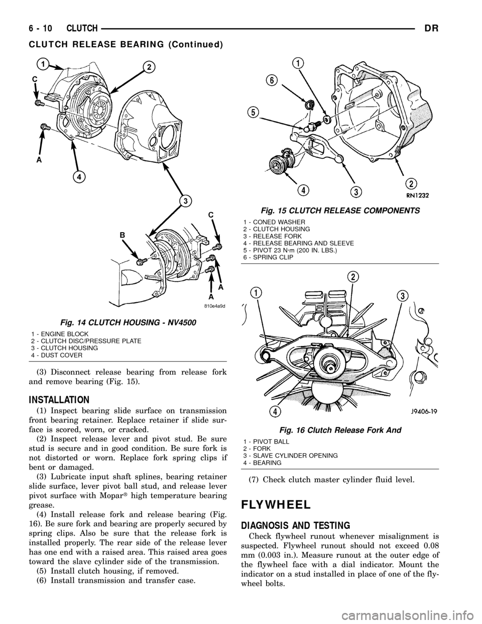
(3) Disconnect release bearing from release fork
and remove bearing (Fig. 15).
INSTALLATION
(1) Inspect bearing slide surface on transmission
front bearing retainer. Replace retainer if slide sur-
face is scored, worn, or cracked.
(2) Inspect release lever and pivot stud. Be sure
stud is secure and in good condition. Be sure fork is
not distorted or worn. Replace fork spring clips if
bent or damaged.
(3) Lubricate input shaft splines, bearing retainer
slide surface, lever pivot ball stud, and release lever
pivot surface with Moparthigh temperature bearing
grease.
(4) Install release fork and release bearing (Fig.
16). Be sure fork and bearing are properly secured by
spring clips. Also be sure that the release fork is
installed properly. The rear side of the release lever
has one end with a raised area. This raised area goes
toward the slave cylinder side of the transmission.
(5) Install clutch housing, if removed.
(6) Install transmission and transfer case.(7) Check clutch master cylinder fluid level.
FLYWHEEL
DIAGNOSIS AND TESTING
Check flywheel runout whenever misalignment is
suspected. Flywheel runout should not exceed 0.08
mm (0.003 in.). Measure runout at the outer edge of
the flywheel face with a dial indicator. Mount the
indicator on a stud installed in place of one of the fly-
wheel bolts.
Fig. 14 CLUTCH HOUSING - NV4500
1 - ENGINE BLOCK
2 - CLUTCH DISC/PRESSURE PLATE
3 - CLUTCH HOUSING
4 - DUST COVER
Fig. 15 CLUTCH RELEASE COMPONENTS
1 - CONED WASHER
2 - CLUTCH HOUSING
3 - RELEASE FORK
4 - RELEASE BEARING AND SLEEVE
5 - PIVOT 23 N´m (200 IN. LBS.)
6 - SPRING CLIP
Fig. 16 Clutch Release Fork And
1 - PIVOT BALL
2 - FORK
3 - SLAVE CYLINDER OPENING
4 - BEARING
6 - 10 CLUTCHDR
CLUTCH RELEASE BEARING (Continued)
Page 313 of 2627
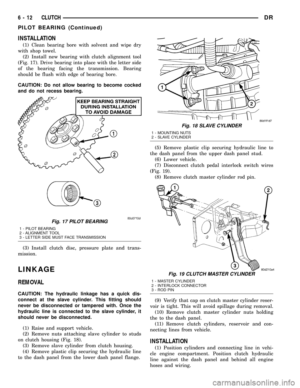
INSTALLATION
(1) Clean bearing bore with solvent and wipe dry
with shop towel.
(2) Install new bearing with clutch alignment tool
(Fig. 17). Drive bearing into place with the letter side
of the bearing facing the transmission. Bearing
should be flush with edge of bearing bore.
CAUTION: Do not allow bearing to become cocked
and do not recess bearing.
(3) Install clutch disc, pressure plate and trans-
mission.
LINKAGE
REMOVAL
CAUTION: The hydraulic linkage has a quick dis-
connect at the slave cylinder. This fitting should
never be disconnected or tampered with. Once the
hydraulic line is connected to the slave cylinder, it
should never be disconnected.
(1) Raise and support vehicle.
(2) Remove nuts attaching slave cylinder to studs
on clutch housing (Fig. 18).
(3) Remove slave cylinder from clutch housing.
(4) Remove plastic clip securing the hydraulic line
to the dash panel from the lower dash panel flange.(5) Remove plastic clip securing hydraulic line to
the dash panel from the upper dash panel stud.
(6) Lower vehicle.
(7) Disconnect clutch pedal interlock switch wires
(Fig. 19).
(8) Remove clutch master cylinder rod pin.
(9) Verify that cap on clutch master cylinder reser-
voir is tight. This will avoid spillage during removal.
(10) Remove clutch master cylinder nuts holding
the to the dash panel.
(11) Remove clutch cylinders, reservoir and con-
necting lines from vehicle.
INSTALLATION
(1) Position cylinders and connecting line in vehi-
cle engine compartment. Position clutch hydraulic
line against the dash panel and behind all engine
hoses and wiring.
Fig. 17 PILOT BEARING
1 - PILOT BEARING
2 - ALIGNMENT TOOL
3 - LETTER SIDE MUST FACE TRANSMISSION
Fig. 18 SLAVE CYLINDER
1 - MOUNTING NUTS
2 - SLAVE CYLINDER
Fig. 19 CLUTCH MASTER CYLINDER
1 - MASTER CYLINDER
2 - INTERLOCK CONNECTOR
3 - ROD PIN
6 - 12 CLUTCHDR
PILOT BEARING (Continued)
Page 369 of 2627

RADIATOR-3.7L/4.7L/5.7L
DESCRIPTION
The radiator is a aluminum cross-flow design with
horizontal tubes through the radiator core and verti-
cal plastic side tanks (Fig. 38).
This radiator does not contain an internal trans-
mission oil cooler.
OPERATION
The radiator supplies sufficient heat transfer using
the cooling fins interlaced between the horizontal
tubes in the radiator core to cool the engine.
DIAGNOSIS AND TESTING - RADIATOR
COOLANT FLOW
Use the following procedure to determine if coolant
is flowing through the cooling system.
(1) Idle engine until operating temperature is
reached. If the upper radiator hose is warm to the
touch, the thermostat is opening and coolant is flow-
ing to the radiator.
WARNING: HOT, PRESSURIZED COOLANT CAN
CAUSE INJURY BY SCALDING. USING A RAG TO
COVER THE RADIATOR PRESSURE CAP, OPEN
RADIATOR CAP SLOWLY TO THE FIRST STOP. THIS
WILL ALLOW ANY BUILT-UP PRESSURE TO VENT
TO THE RESERVE/OVERFLOW TANK. AFTER PRES-
SURE BUILD-UP HAS BEEN RELEASED, REMOVE
CAP FROM FILLER NECK.
(2) Drain a small amount of coolant from the radi-
ator until the ends of the radiator tubes are visible
through the filler neck. Idle the engine at normal
operating temperature. If coolant is flowing past the
exposed tubes, the coolant is circulating.
REMOVAL
(1) Disconnect battery negative cables.
WARNING: DO NOT REMOVE THE CYLINDER
BLOCK DRAIN PLUGS OR LOOSEN THE RADIATOR
DRAINCOCK WITH THE SYSTEM HOT AND UNDER
PRESSURE. SERIOUS BURNS FROM THE COOL-
ANT CAN OCCUR.
(2) Drain the cooling system (Refer to 7 - COOL-
ING - STANDARD PROCEDURE).
WARNING: CONSTANT TENSION HOSE CLAMPS
ARE USED ON MOST COOLING SYSTEM HOSES.
WHEN REMOVING OR INSTALLING, USE ONLY
TOOLS DESIGNED FOR SERVICING THIS TYPE OF
CLAMP. ALWAYS WEAR SAFETY GLASSES WHEN
SERVICING CONSTANT TENSION CLAMPS.CAUTION: A number or letter is stamped into the
tongue of constant tension clamps. If replacement
is necessary, use only an original equipment clamp
with a matching number or letter and the correct
width.
(3) Remove the hose clamps and hoses from radia-
tor.
(4) Remove the coolant reserve/overflow tank hose
from the radiator filler neck.
(5) Remove the coolant reserve/overflow tank from
the fan shroud (pull straight up). The tank slips into
slots on the fan shroud.
(6) Unclip the power steering hoses from the fan
shroud.
(7) Disconnect the electrical connectors at the
windshield washer reservoir tank and remove the
tank.
(8) Remove the fan shroud mounting bolts and pull
up and out of the radiator tank clips (Fig. 36). Posi-
tion shroud rearward over the fan blades towards
engine.
(9) Disconnect the transmission cooler lines from
the transmission cooler, then plug the transmission
lines and cooler to prevent leakage.
(10) Disconnect the power steering lines from the
power steering cooler, then plug the power steering
lines and cooler to prevent leakage.
Fig. 36 Fan Shroud - Gas Engine
1 - RADIATOR
2 - SCREWS
3 - FAN SHROUD
4 - SLIDE MOUNT
7 - 54 ENGINEDR
Page 370 of 2627

(11) Remove the two radiator upper mounting
bolts (Fig. 37).
(12) Lift the radiator straight up and out of the
engine compartment. Take care not to damage cool-
ing fins or tubes on the radiator and oil coolers when
removing.
NOTE: The radiator is equipped with one alignment
dowel on the bottom of the outlet tank and one
retaining bracket on the front side of the inlet tank.
Both features have rubber insulators attached to
them that must be present. The alignment dowel fits
into a hole at the bottom of the front end sheet
metal vertical support post and the support bracket
rests on top of the lower radiator closure tube.
CLEANING
Clean radiator fins are necessary for good heat
transfer. The radiator and oil cooler fins should be
cleaned when an accumulation of debris has
occurred. With the engine cold, apply cold water and
compressed air to the back (engine side) of the radi-
ator to flush the radiator and/or oil coolers of debris.
INSPECTION
Inspect the radiator side tanks for cracks, and bro-
ken or missing fittings. Inspect the joint where the
tanks seam up to the radiator core for signs of leak-
age and/or deteriorating seals.
Inspect radiator core for corroded, bent or missing
cooling fins. Inspect the core for bent or damaged
cooling tubes.
INSTALLATION
(1) Position the fan shroud over the fan blades
rearward towards engine.
(2) Install the rubber insulators to the lower radi-
ator mounting features (alignment dowel and support
bracket at the lower part of the radiator).
(3) Lower the radiator into position while guiding
the alignment dowel into the vertical post bracket.
Position and seat the lower radiator support bracket
onto the lower radiator closure tube.
(4) Install the upper radiator mounting bolts.
Tighten bolts to 10 N´m (90 in. lbs.).
(5) Connect the lower radiator hose and install the
clamp in the proper position.
(6) Connect the power steering hoses to the power
steering oil cooler and install the clamps.
(7) Connect the transmission oil cooler lines to the
transmission oil cooler and install the secondary
latches.
(8) Position the fan shroud into the mounting clips
on the radiator tanks and secure with bolts. Tighten
the bolts to 8.5 N´m (75 in. lbs.).
(9) Secure the power steering hoses into the clip
on the lower fan shroud.
(10) Install the windshield washer reservoir tank
and connect the hose and electrical connector.
(11) Install coolant reserve/overflow container
hose(s) to radiator filler neck and secure properly
with clamps.
(12) Install coolant reserve/overflow container or
degas container to fan shroud and tighten the bolts
to 8.5 N´m (75 in. lbs.).
(13) Connect upper radiator hose and install
clamp.
(14) Install battery negative cable.
(15) Fill cooling system with coolant (Refer to 7 -
COOLING - STANDARD PROCEDURE).
(16) Operate the engine until it reaches normal
operating temperature. Check cooling system fluid
levels.
Fig. 37 Radiator
1 - SCREW
2 - SCREW
3 - LOWER MOUNT
4 - RADIATOR
5 - DRAINCOCK
6 -LOWER MOUNT
DRENGINE 7 - 55
RADIATOR-3.7L/4.7L/5.7L (Continued)