cylinder head replacement DODGE RAM 1500 1998 2.G Workshop Manual
[x] Cancel search | Manufacturer: DODGE, Model Year: 1998, Model line: RAM 1500, Model: DODGE RAM 1500 1998 2.GPages: 2627
Page 318 of 2627
DESCRIPTION - COOLING SYSTEM FLOW -
5.9L DIESEL
The diesel engine cooling system consists of :
²Cross-flow radiator
²Belt driven water pump
²Cooling fan (attached to the electronic viscous
fan drive)
²Belt driven Electronic viscous fan drive
²Two piece fan shroud
²Radiator pressure cap
²Vertically mounted thermostat
²Coolant reserve/recovery system
²Transmission oil cooler
²Coolant
Coolant flow circuits for the 5.9L diesel engine are
shown in (Fig. 3).
DESCRIPTION - HOSE CLAMPS
The cooling system utilizes spring type hose
clamps. If a spring type clamp replacement is neces-
sary, replace with the original Mopartequipment
spring type clamp.
CAUTION: A number or letter is stamped into the
tongue of constant tension clamps. If replacement
is necessary, use only a original equipment clamp
with matching number or letter and ensure the
clamp has the same size width (Fig. 4).
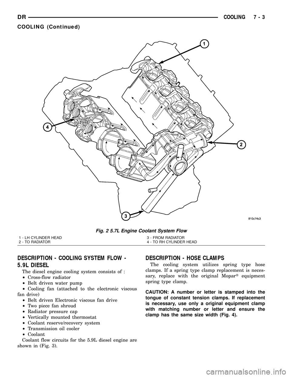
Fig. 2 5.7L Engine Coolant System Flow
1 - LH CYLINDER HEAD
2 - TO RADIATOR3 - FROM RADIATOR
4 - TO RH CYLINDER HEAD
DRCOOLING 7 - 3
COOLING (Continued)
Page 362 of 2627
DIAGNOSIS AND TESTING - THERMOSTAT
The cooling system used with the diesel engine
provides the extra coolant capacity and extra cooling
protection needed for higher GVWR (Gross Vehicle
Weight Rating) and GCWR (Gross Combined Weight
Rating) vehicles.
This system capacity will not effect warm up or
cold weather operating characteristics if the thermo-
stat is operating properly. This is because coolant
will be held in the engine until it reaches the ther-
mostat ªsetº temperature.
Diesel engines, due to their inherent efficiency are
slower to warm up than gasoline powered engines,
and will operate at lower temperatures when the
vehicle is unloaded. Because of this, lower tempera-
ture gauge readings for diesel versus gasoline
engines may, at times be normal.
Typically, complaints of low engine coolant temper-
ature are observed as low heater output when com-
bined with cool or cold outside temperatures.
To help promote faster engine warm-up, the elec-
tric engine block heater must be used with cool or
cold outside temperatures. This will help keep the
engine coolant warm when the vehicle is parked.
A ªCold Weather Coverº is available from the parts
department through the Mopar Accessories product
line. This accessory cover is designed to block airflow
entering the radiator and engine compartment to
promote faster engine warm-up. It attaches to the
front of the vehicle at the grill opening.The cover is
to be used with cool or cold temperatures only.
If used with high outside temperatures, serious
engine damage could result.Refer to the litera-
ture supplied with the cover for additional informa-
tion.
(1) To determine if the thermostat is defective, it
must be removed from the vehicle (Refer to 7 -
COOLING/ENGINE/ENGINE COOLANT THERMO-
STAT - REMOVAL).
(2) After the thermostat has been removed, exam-
ine the thermostat and inside of thermostat housing
for contaminants. If contaminants are found, the
thermostat may already be in a ªstuck openº position.
Flush the cooling system before replacing thermostat
(Refer to 7 - COOLING - STANDARD PROCE-
DURE).
(3) Place the thermostat into a container filled
with water.
(4) Place the container on a hot plate or other suit-
able heating device.
(5) Place a commercially available radiator ther-
mometer into the water.
(6) Apply heat to the water while observing the
thermostat and thermometer.
(7) The thermostat will begin to open at 85.5 -
89.4ÉC. (186 - 193ÉF ). If the valve starts to movebefore this temperature is reached, it is opening too
early. Replace thermostat. The thermostat should be
fully open (valve will stop moving) at 97ÉC (207ÉF). If
the valve is still moving when the water temperature
reaches 97ÉC (207ÉF), it is opening too late. Replace
thermostat. If the valve refuses to move at any time,
replace thermostat.
REMOVAL
WARNING: DO NOT LOOSEN THE RADIATOR
DRAINCOCK WITH THE SYSTEM HOT AND PRES-
SURIZED. SERIOUS BURNS FROM THE COOLANT
CAN OCCUR.
Do not waste reusable coolant. If the solution is
clean, drain the coolant into a clean container for
reuse.
(1) Disconnect the battery negative cables.
(2) Drain cooling system until coolant level is
below thermostat (Refer to 7 - COOLING - STAN-
DARD PROCEDURE).
WARNING: CONSTANT TENSION HOSE CLAMPS
ARE USED ON MOST COOLING SYSTEM HOSES.
WHEN REMOVING OR INSTALLING, USE ONLY
TOOLS DESIGNED FOR SERVICING THIS TYPE OF
CLAMP, SUCH AS SPECIAL CLAMP TOOL (NUMBER
6094).
CAUTION: A number or letter is stamped into the
tongue of constant tension clamps. If replacement
is necessary, use only an original equipment clamp
with a matching number or letter.
(3) Remove radiator hose clamp and hose from
thermostat housing.
(4) Remove the three (3) water outlet-to-cylinder
head bolts and remove the water outlet connector
(Fig. 26).
(5) Clean the mating surfaces of the water outlet
connector and clean the thermostat seat groove at
the top of the thermostat housing (Fig. 26).
INSTALLATION
(1) Inspect thermostat seal for cuts or nicks.
Replace if damaged.
(2) Install the thermostat into the groove in the
top of the cylinder head (Fig. 26).
(3) Install the thermostat housing and bolts.
Tighten the bolts to 10 N´m (89 in. lbs.) torque.
(4) Install the radiator upper hose and clamp.
(5) Fill the cooling system with coolant (Refer to 7
- COOLING - STANDARD PROCEDURE).
(6) Connect the battery negative cables.
DRENGINE 7 - 47
ENGINE COOLANT THERMOSTAT - 5.9L DIESEL (Continued)
Page 1244 of 2627
AIR CLEANER ELEMENT
REMOVAL
Filter Element Only
Housing removal is not necessary for element (fil-
ter) replacement.
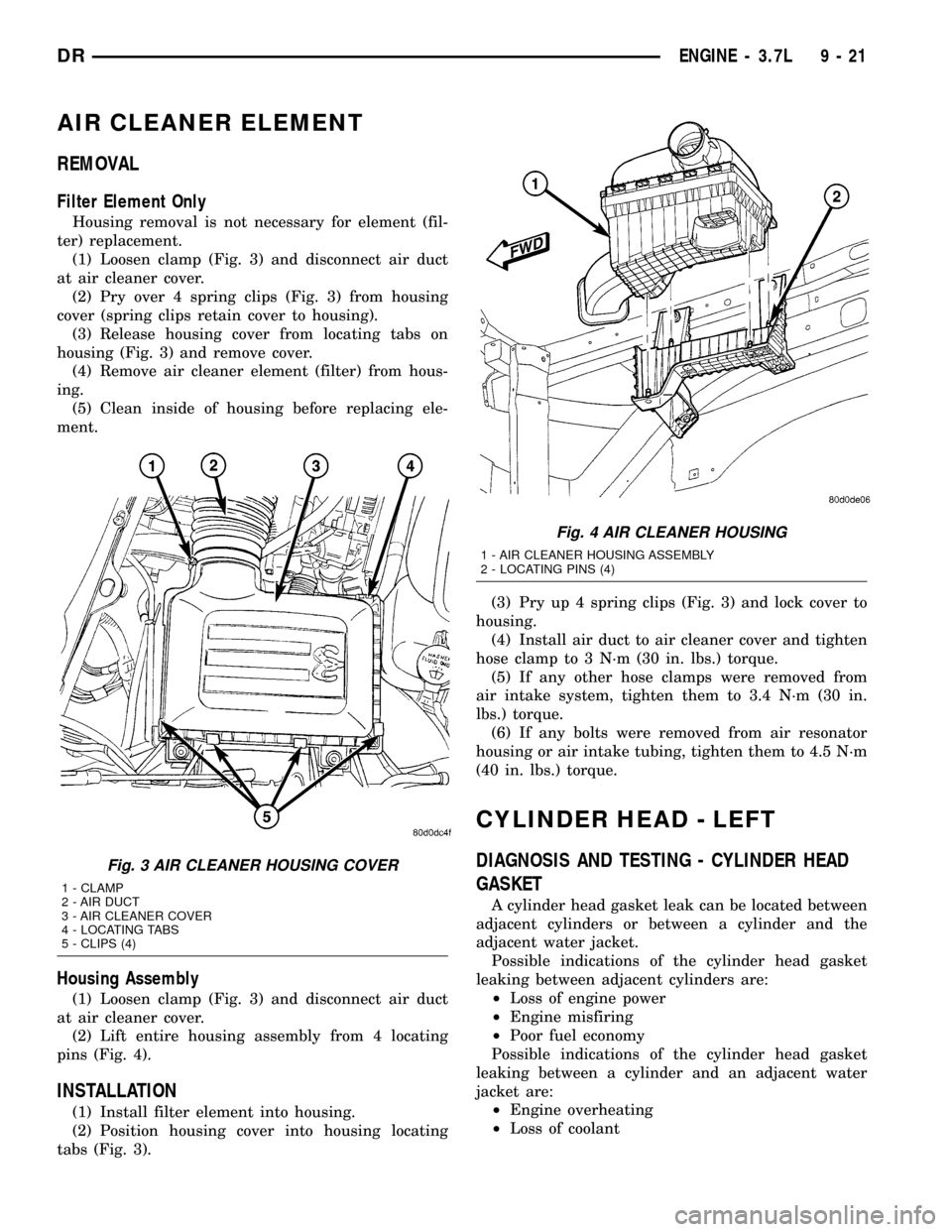
(1) Loosen clamp (Fig. 3) and disconnect air duct
at air cleaner cover.
(2) Pry over 4 spring clips (Fig. 3) from housing
cover (spring clips retain cover to housing).
(3) Release housing cover from locating tabs on
housing (Fig. 3) and remove cover.
(4) Remove air cleaner element (filter) from hous-
ing.
(5) Clean inside of housing before replacing ele-
ment.
Housing Assembly
(1) Loosen clamp (Fig. 3) and disconnect air duct
at air cleaner cover.
(2) Lift entire housing assembly from 4 locating
pins (Fig. 4).
INSTALLATION
(1) Install filter element into housing.
(2) Position housing cover into housing locating
tabs (Fig. 3).(3) Pry up 4 spring clips (Fig. 3) and lock cover to
housing.
(4) Install air duct to air cleaner cover and tighten
hose clamp to 3 N´m (30 in. lbs.) torque.
(5) If any other hose clamps were removed from
air intake system, tighten them to 3.4 N´m (30 in.
lbs.) torque.
(6) If any bolts were removed from air resonator
housing or air intake tubing, tighten them to 4.5 N´m
(40 in. lbs.) torque.
CYLINDER HEAD - LEFT
DIAGNOSIS AND TESTING - CYLINDER HEAD
GASKET
A cylinder head gasket leak can be located between
adjacent cylinders or between a cylinder and the
adjacent water jacket.
Possible indications of the cylinder head gasket
leaking between adjacent cylinders are:
²Loss of engine power
²Engine misfiring
²Poor fuel economy
Possible indications of the cylinder head gasket
leaking between a cylinder and an adjacent water
jacket are:
²Engine overheating
²Loss of coolant
Fig. 3 AIR CLEANER HOUSING COVER
1 - CLAMP
2 - AIR DUCT
3 - AIR CLEANER COVER
4 - LOCATING TABS
5 - CLIPS (4)
Fig. 4 AIR CLEANER HOUSING
1 - AIR CLEANER HOUSING ASSEMBLY
2 - LOCATING PINS (4)
DRENGINE - 3.7L 9 - 21
Page 1300 of 2627
block. A large washer on the idler shaft bolt and the
rear flange of the idler shaft are used to control
sprocket thrust movement. Pressurized oil is routed
through the center of the idler shaft to provide lubri-
cation for the two bushings used in the idler sprocket
assembly.
There are two secondary drive chains, both are
roller type, one to drive the camshaft in each SOHC
cylinder head. There are no shaft speed changes in
the secondary chain drive system. Each secondary
chain drives a 26 tooth cam sprocket directly from
the 26 tooth sprocket on the idler sprocket assembly.
A fixed chain guide and a hydraulic oil damped ten-
sioner are used to maintain tension in each second-
ary chain system. The hydraulic tensioners for the
secondary chain systems are fed pressurized oil from
oil reservoir pockets in the block. Each tensioner
incorporates a controlled leak path through a device
known as a vent disc located in the nose of the piston
to manage chain loads. Each tensioner also has a
mechanical ratchet system that limits chain slack if
the tensioner piston bleeds down after engine shut
down. The tensioner arms and guides also utilize
nylon wear faces for low friction and long wear. The
secondary timing chains receive lubrication from a
small orifice in the tensioners. This orifice is pro-
tected from clogging by a fine mesh screen which is
located on the back of the hydraulic tensioners.
STANDARD PROCEDURE
MEASURING TIMING CHAIN WEAR
NOTE: This procedure must be performed with the
timing chain cover removed.
(1) Remove the timing chain cover (Refer to 9 -
ENGINE/VALVE TIMING/TIMING BELT/CHAIN
AND SPROCKETS - REMOVAL).
(2) To determine if the secondary timing chains
are worn, rotate the engine clockwise until maximum
tensioner piston extension is obtained. Measure the
distance between the secondary timing chain ten-
sioner housing and the step ledge on the piston. The
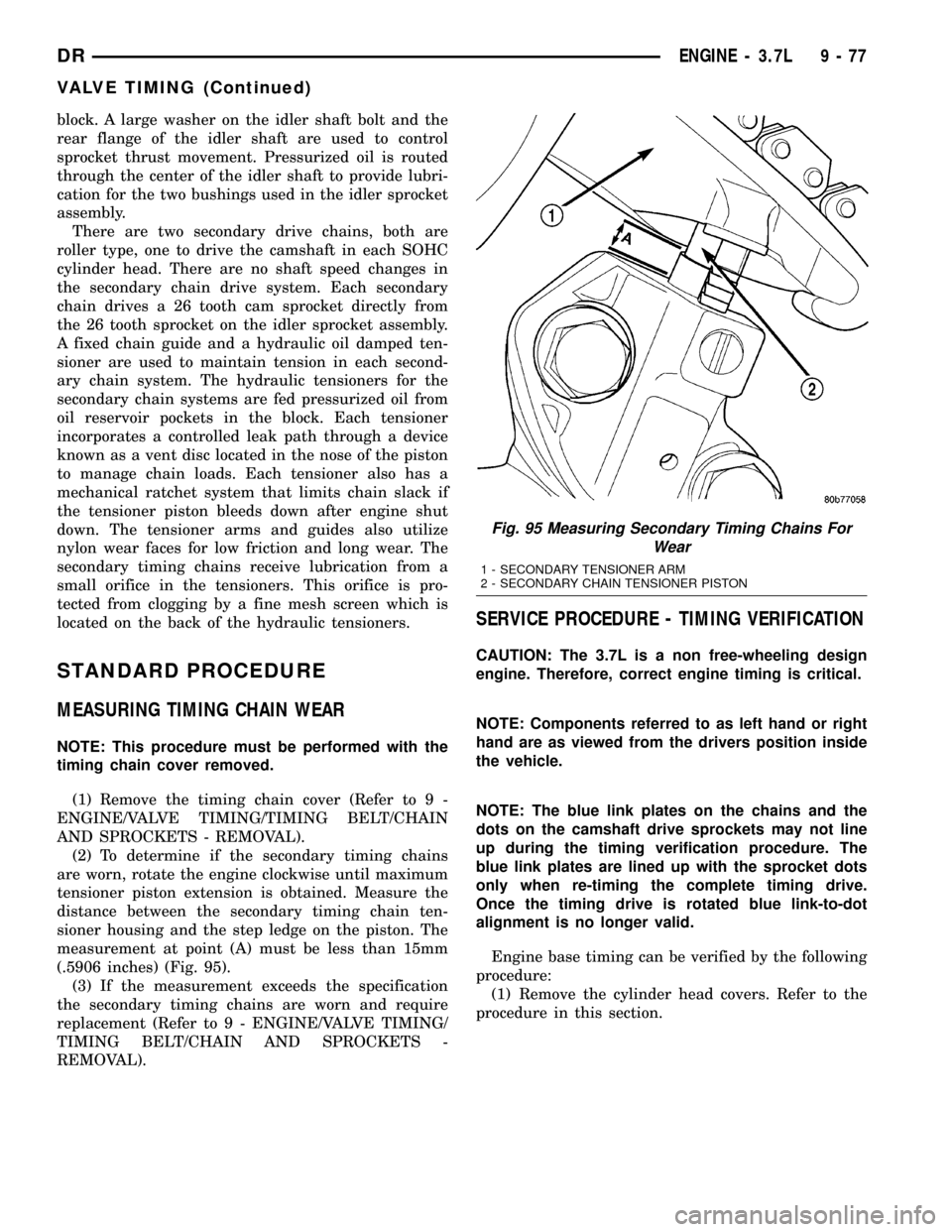
measurement at point (A) must be less than 15mm
(.5906 inches) (Fig. 95).
(3) If the measurement exceeds the specification
the secondary timing chains are worn and require
replacement (Refer to 9 - ENGINE/VALVE TIMING/
TIMING BELT/CHAIN AND SPROCKETS -
REMOVAL).
SERVICE PROCEDURE - TIMING VERIFICATION
CAUTION: The 3.7L is a non free-wheeling design
engine. Therefore, correct engine timing is critical.
NOTE: Components referred to as left hand or right
hand are as viewed from the drivers position inside
the vehicle.
NOTE: The blue link plates on the chains and the
dots on the camshaft drive sprockets may not line
up during the timing verification procedure. The
blue link plates are lined up with the sprocket dots
only when re-timing the complete timing drive.
Once the timing drive is rotated blue link-to-dot
alignment is no longer valid.
Engine base timing can be verified by the following
procedure:
(1) Remove the cylinder head covers. Refer to the
procedure in this section.
Fig. 95 Measuring Secondary Timing Chains For
Wear
1 - SECONDARY TENSIONER ARM
2 - SECONDARY CHAIN TENSIONER PISTON
DRENGINE - 3.7L 9 - 77
VALVE TIMING (Continued)
Page 1307 of 2627
(7) Remove access plug from left and right cylinder
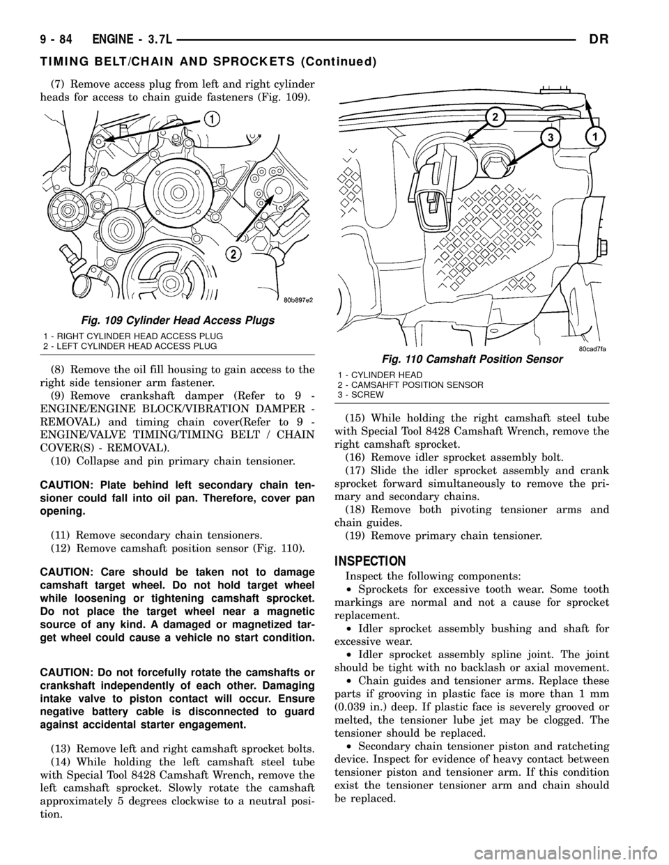
heads for access to chain guide fasteners (Fig. 109).
(8) Remove the oil fill housing to gain access to the
right side tensioner arm fastener.
(9) Remove crankshaft damper (Refer to 9 -
ENGINE/ENGINE BLOCK/VIBRATION DAMPER -
REMOVAL) and timing chain cover(Refer to 9 -
ENGINE/VALVE TIMING/TIMING BELT / CHAIN
COVER(S) - REMOVAL).
(10) Collapse and pin primary chain tensioner.
CAUTION: Plate behind left secondary chain ten-
sioner could fall into oil pan. Therefore, cover pan
opening.
(11) Remove secondary chain tensioners.
(12) Remove camshaft position sensor (Fig. 110).
CAUTION: Care should be taken not to damage
camshaft target wheel. Do not hold target wheel
while loosening or tightening camshaft sprocket.
Do not place the target wheel near a magnetic
source of any kind. A damaged or magnetized tar-
get wheel could cause a vehicle no start condition.
CAUTION: Do not forcefully rotate the camshafts or
crankshaft independently of each other. Damaging
intake valve to piston contact will occur. Ensure
negative battery cable is disconnected to guard
against accidental starter engagement.
(13) Remove left and right camshaft sprocket bolts.
(14) While holding the left camshaft steel tube
with Special Tool 8428 Camshaft Wrench, remove the
left camshaft sprocket. Slowly rotate the camshaft
approximately 5 degrees clockwise to a neutral posi-
tion.(15) While holding the right camshaft steel tube
with Special Tool 8428 Camshaft Wrench, remove the
right camshaft sprocket.
(16) Remove idler sprocket assembly bolt.
(17) Slide the idler sprocket assembly and crank
sprocket forward simultaneously to remove the pri-
mary and secondary chains.
(18) Remove both pivoting tensioner arms and
chain guides.
(19) Remove primary chain tensioner.
INSPECTION
Inspect the following components:
²Sprockets for excessive tooth wear. Some tooth
markings are normal and not a cause for sprocket
replacement.
²Idler sprocket assembly bushing and shaft for
excessive wear.
²Idler sprocket assembly spline joint. The joint
should be tight with no backlash or axial movement.
²Chain guides and tensioner arms. Replace these
parts if grooving in plastic face is more than 1 mm
(0.039 in.) deep. If plastic face is severely grooved or
melted, the tensioner lube jet may be clogged. The
tensioner should be replaced.
²Secondary chain tensioner piston and ratcheting
device. Inspect for evidence of heavy contact between
tensioner piston and tensioner arm. If this condition
exist the tensioner tensioner arm and chain should
be replaced.
Fig. 109 Cylinder Head Access Plugs
1 - RIGHT CYLINDER HEAD ACCESS PLUG
2 - LEFT CYLINDER HEAD ACCESS PLUG
Fig. 110 Camshaft Position Sensor
1 - CYLINDER HEAD
2 - CAMSAHFT POSITION SENSOR
3 - SCREW
9 - 84 ENGINE - 3.7LDR
TIMING BELT/CHAIN AND SPROCKETS (Continued)
Page 1330 of 2627
AIR CLEANER ELEMENT
REMOVAL
Filter Element Only
Housing removal is not necessary for element (fil-
ter) replacement.
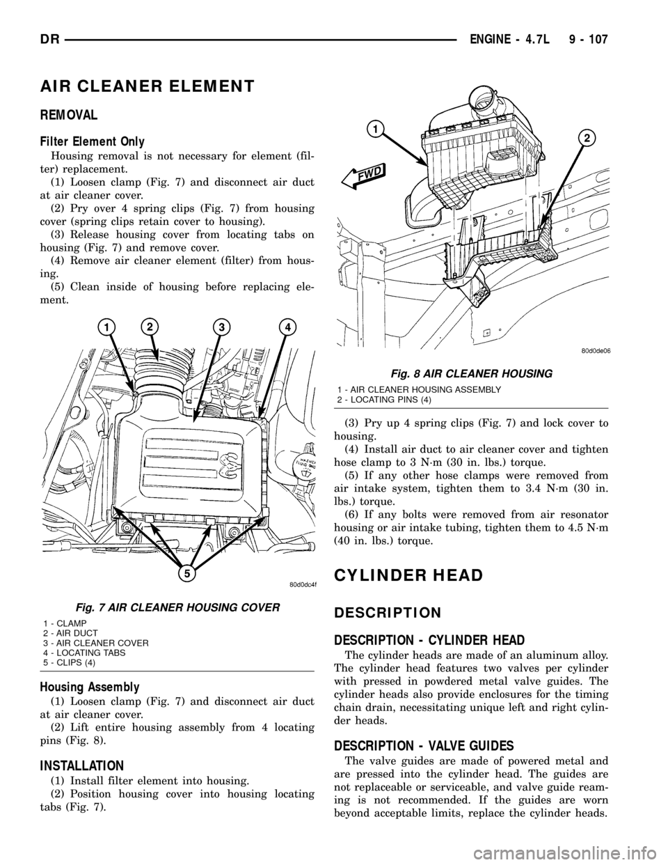
(1) Loosen clamp (Fig. 7) and disconnect air duct
at air cleaner cover.
(2) Pry over 4 spring clips (Fig. 7) from housing
cover (spring clips retain cover to housing).
(3) Release housing cover from locating tabs on
housing (Fig. 7) and remove cover.
(4) Remove air cleaner element (filter) from hous-
ing.
(5) Clean inside of housing before replacing ele-
ment.
Housing Assembly
(1) Loosen clamp (Fig. 7) and disconnect air duct
at air cleaner cover.
(2) Lift entire housing assembly from 4 locating
pins (Fig. 8).
INSTALLATION
(1) Install filter element into housing.
(2) Position housing cover into housing locating
tabs (Fig. 7).(3) Pry up 4 spring clips (Fig. 7) and lock cover to
housing.
(4) Install air duct to air cleaner cover and tighten
hose clamp to 3 N´m (30 in. lbs.) torque.
(5) If any other hose clamps were removed from
air intake system, tighten them to 3.4 N´m (30 in.
lbs.) torque.
(6) If any bolts were removed from air resonator
housing or air intake tubing, tighten them to 4.5 N´m
(40 in. lbs.) torque.
CYLINDER HEAD
DESCRIPTION
DESCRIPTION - CYLINDER HEAD
The cylinder heads are made of an aluminum alloy.
The cylinder head features two valves per cylinder
with pressed in powdered metal valve guides. The
cylinder heads also provide enclosures for the timing
chain drain, necessitating unique left and right cylin-
der heads.
DESCRIPTION - VALVE GUIDES
The valve guides are made of powered metal and
are pressed into the cylinder head. The guides are
not replaceable or serviceable, and valve guide ream-
ing is not recommended. If the guides are worn
beyond acceptable limits, replace the cylinder heads.
Fig. 7 AIR CLEANER HOUSING COVER
1 - CLAMP
2 - AIR DUCT
3 - AIR CLEANER COVER
4 - LOCATING TABS
5 - CLIPS (4)
Fig. 8 AIR CLEANER HOUSING
1 - AIR CLEANER HOUSING ASSEMBLY
2 - LOCATING PINS (4)
DRENGINE - 4.7L 9 - 107
Page 1390 of 2627
sprocket assembly. A fixed chain guide and a hydrau-
lic oil damped tensioner are used to maintain tension
in each secondary chain system. The hydraulic ten-
sioners for the secondary chain systems are fed pres-
surized oil from oil reservoir pockets in the block.
Each tensioner also has a mechanical ratchet system
that limits chain slack if the tensioner piston bleeds
down after engine shut down. The tensioner arms
and guides also utilize nylon wear faces for low fric-
tion and long wear. The secondary timing chains
receive lubrication from a small orifice in the ten-
sioners. This orifice is protected from clogging by a
fine mesh screen which is located on the back of the
hydraulic tensioners.
STANDARD PROCEDURE
STANDARD PROCEDUREÐMEASURING
TIMING CHAIN WEAR
NOTE: This procedure must be performed with the
timing chain cover removed.
(1) Remove the timing chain cover. (Refer to 9 -
ENGINE/VALVE TIMING/TIMING BELT / CHAIN
COVER(S) - REMOVAL).
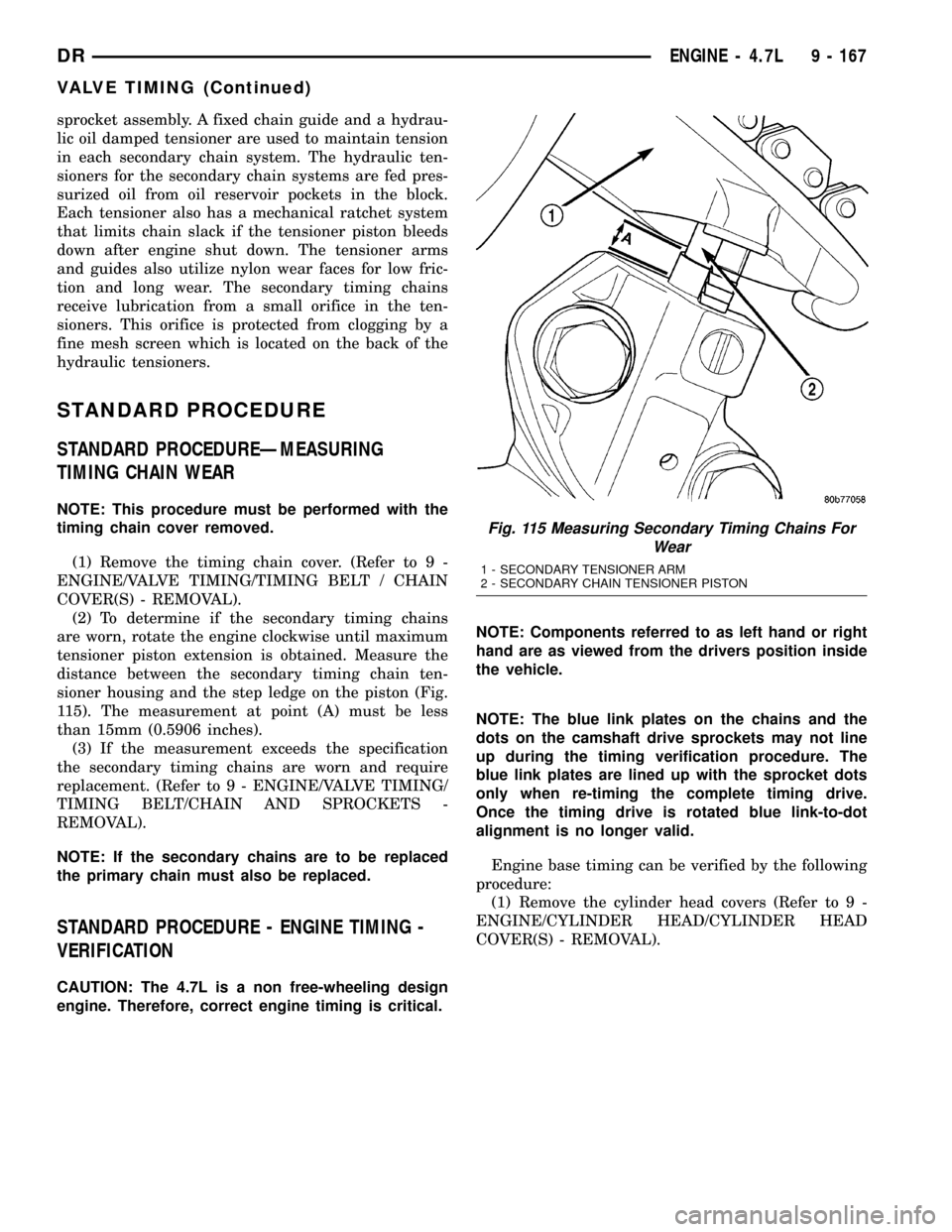
(2) To determine if the secondary timing chains
are worn, rotate the engine clockwise until maximum
tensioner piston extension is obtained. Measure the
distance between the secondary timing chain ten-
sioner housing and the step ledge on the piston (Fig.
115). The measurement at point (A) must be less
than 15mm (0.5906 inches).
(3) If the measurement exceeds the specification
the secondary timing chains are worn and require
replacement. (Refer to 9 - ENGINE/VALVE TIMING/
TIMING BELT/CHAIN AND SPROCKETS -
REMOVAL).
NOTE: If the secondary chains are to be replaced
the primary chain must also be replaced.
STANDARD PROCEDURE - ENGINE TIMING -
VERIFICATION
CAUTION: The 4.7L is a non free-wheeling design
engine. Therefore, correct engine timing is critical.NOTE: Components referred to as left hand or right
hand are as viewed from the drivers position inside
the vehicle.
NOTE: The blue link plates on the chains and the
dots on the camshaft drive sprockets may not line
up during the timing verification procedure. The
blue link plates are lined up with the sprocket dots
only when re-timing the complete timing drive.
Once the timing drive is rotated blue link-to-dot
alignment is no longer valid.
Engine base timing can be verified by the following
procedure:
(1) Remove the cylinder head covers (Refer to 9 -
ENGINE/CYLINDER HEAD/CYLINDER HEAD
COVER(S) - REMOVAL).
Fig. 115 Measuring Secondary Timing Chains For
Wear
1 - SECONDARY TENSIONER ARM
2 - SECONDARY CHAIN TENSIONER PISTON
DRENGINE - 4.7L 9 - 167
VALVE TIMING (Continued)
Page 1422 of 2627
AIR INTAKE SYSTEM
REMOVAL
Filter Element Only
Housing removal is not necessary for element (fil-
ter) replacement.
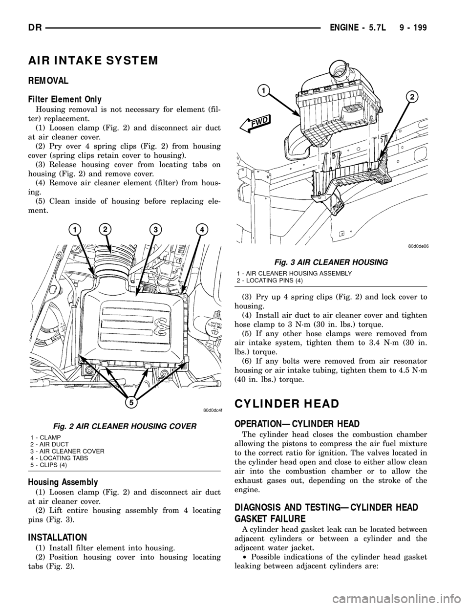
(1) Loosen clamp (Fig. 2) and disconnect air duct
at air cleaner cover.
(2) Pry over 4 spring clips (Fig. 2) from housing
cover (spring clips retain cover to housing).
(3) Release housing cover from locating tabs on
housing (Fig. 2) and remove cover.
(4) Remove air cleaner element (filter) from hous-
ing.
(5) Clean inside of housing before replacing ele-
ment.
Housing Assembly
(1) Loosen clamp (Fig. 2) and disconnect air duct
at air cleaner cover.
(2) Lift entire housing assembly from 4 locating
pins (Fig. 3).
INSTALLATION
(1) Install filter element into housing.
(2) Position housing cover into housing locating
tabs (Fig. 2).(3) Pry up 4 spring clips (Fig. 2) and lock cover to
housing.
(4) Install air duct to air cleaner cover and tighten
hose clamp to 3 N´m (30 in. lbs.) torque.
(5) If any other hose clamps were removed from
air intake system, tighten them to 3.4 N´m (30 in.
lbs.) torque.
(6) If any bolts were removed from air resonator
housing or air intake tubing, tighten them to 4.5 N´m
(40 in. lbs.) torque.
CYLINDER HEAD
OPERATIONÐCYLINDER HEAD
The cylinder head closes the combustion chamber
allowing the pistons to compress the air fuel mixture
to the correct ratio for ignition. The valves located in
the cylinder head open and close to either allow clean
air into the combustion chamber or to allow the
exhaust gases out, depending on the stroke of the
engine.
DIAGNOSIS AND TESTINGÐCYLINDER HEAD
GASKET FAILURE
A cylinder head gasket leak can be located between
adjacent cylinders or between a cylinder and the
adjacent water jacket.
²Possible indications of the cylinder head gasket
leaking between adjacent cylinders are:
Fig. 2 AIR CLEANER HOUSING COVER
1 - CLAMP
2 - AIR DUCT
3 - AIR CLEANER COVER
4 - LOCATING TABS
5 - CLIPS (4)
Fig. 3 AIR CLEANER HOUSING
1 - AIR CLEANER HOUSING ASSEMBLY
2 - LOCATING PINS (4)
DRENGINE - 5.7L 9 - 199
Page 1475 of 2627
CLEANINGÐPUSHRODS
Clean the pushrods in a suitable solvent. Rinse in
hot water and blow dry with compressed air. If nec-
essary, use a wire brush or wheel to remove stubborn
deposits.
INSPECTION
INSPECTION - CYLINDER HEAD
Inspect the cylinder head for cracks in the combus-
tion surface. Pressure test any cylinder head that is
visibly cracked. A cylinder head that is cracked
between the injector bore and valve seat can be pres-
sure tested and reused if OK; however, if the crack
extendsintothe valve seat insert bore, the cylinder
headmustbe replaced.
Visually inspect the cylinder block and head com-
bustion surfaces for localized dips or imperfections.
Check the cylinder head and block combustion sur-
faces for overall out-of-flatness. If either the visual or
manual inspection exceeds the limits, then the head
or block must be surfaced.
Check the top surface for damage caused by the
cylinder head gasket leaking between cylinders.
Inspect the block and head surface for nicks, ero-
sion, etc.
Check the head distortion. Maximum overall vari-
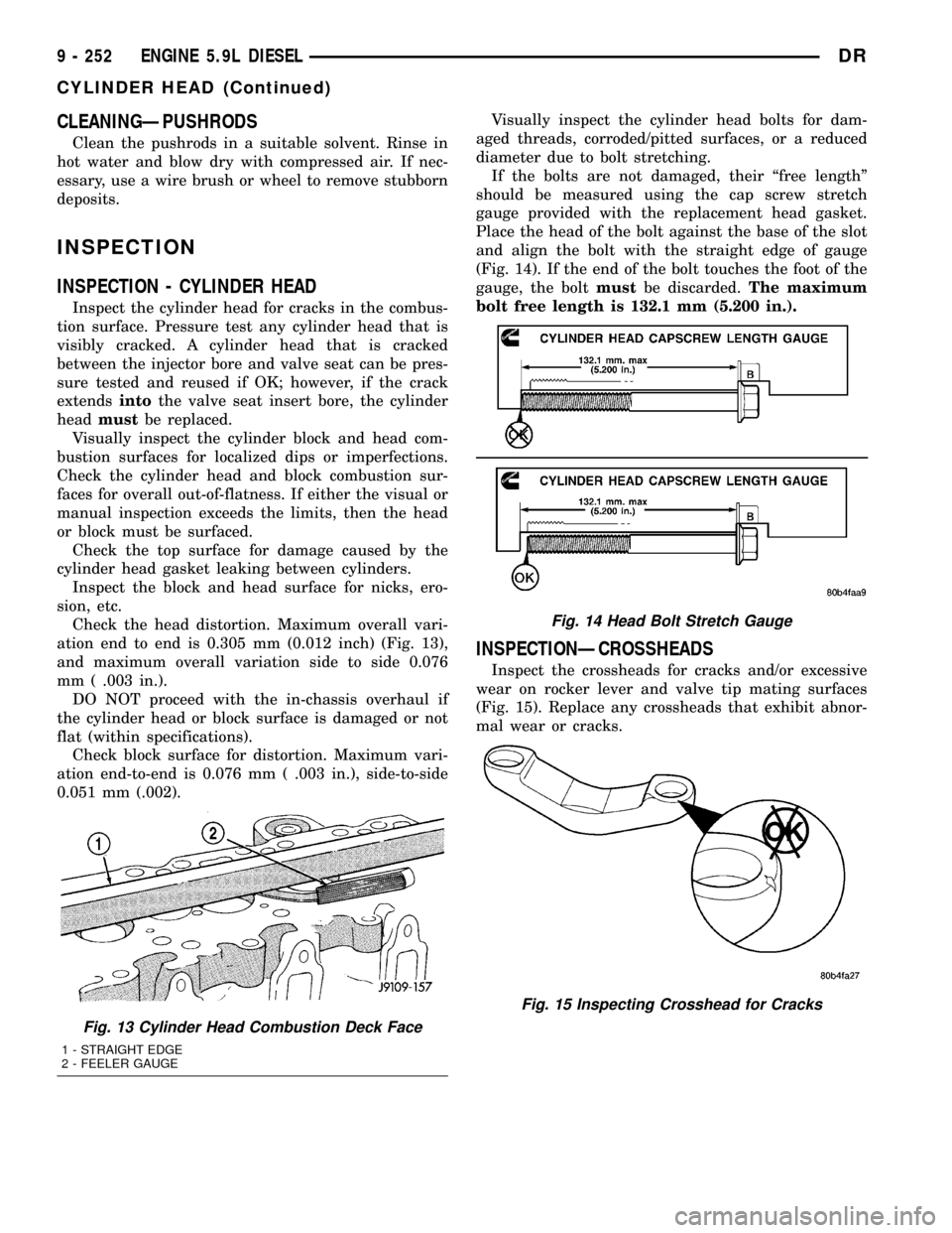
ation end to end is 0.305 mm (0.012 inch) (Fig. 13),
and maximum overall variation side to side 0.076
mm ( .003 in.).
DO NOT proceed with the in-chassis overhaul if
the cylinder head or block surface is damaged or not
flat (within specifications).
Check block surface for distortion. Maximum vari-
ation end-to-end is 0.076 mm ( .003 in.), side-to-side
0.051 mm (.002).Visually inspect the cylinder head bolts for dam-
aged threads, corroded/pitted surfaces, or a reduced
diameter due to bolt stretching.
If the bolts are not damaged, their ªfree lengthº
should be measured using the cap screw stretch
gauge provided with the replacement head gasket.
Place the head of the bolt against the base of the slot
and align the bolt with the straight edge of gauge
(Fig. 14). If the end of the bolt touches the foot of the
gauge, the boltmustbe discarded.The maximum
bolt free length is 132.1 mm (5.200 in.).
INSPECTIONÐCROSSHEADS
Inspect the crossheads for cracks and/or excessive
wear on rocker lever and valve tip mating surfaces
(Fig. 15). Replace any crossheads that exhibit abnor-
mal wear or cracks.
Fig. 13 Cylinder Head Combustion Deck Face
1 - STRAIGHT EDGE
2 - FEELER GAUGE
Fig. 14 Head Bolt Stretch Gauge
Fig. 15 Inspecting Crosshead for Cracks
9 - 252 ENGINE 5.9L DIESELDR
CYLINDER HEAD (Continued)
Page 1626 of 2627
FUEL LEVEL SENDING UNIT /
SENSOR
DESCRIPTION
The fuel gauge sending unit (fuel level sensor) is
attached to the side of the fuel tank module. The
sending unit consists of a float, an arm, and a vari-
able resistor track (card).
OPERATION
The fuel tank module on diesel powered models
has 2 different circuits (wires). Two of these circuits
are used at the fuel gauge sending unit for fuel
gauge operation. The diesel engine does not have a
fuel tank module mounted electric fuel pump. The
electric fuel pump (fuel transfer pump) is mounted to
the engine.
For Fuel Gauge Operation:A constant input
voltage source of about 12 volts (battery voltage) is
supplied to the resistor track on the fuel gauge send-
ing unit. This is fed directly from the Engine Control
Module (ECM).NOTE: For diagnostic purposes,
this 12V power source can only be verified with
the circuit opened (fuel tank module electrical
connector unplugged). With the connectors
plugged, output voltages will vary from about .6
volts at FULL, to about 7.0 volts at EMPTY.The
resistor track is used to vary the voltage (resistance)
depending on fuel tank float level. As fuel level
increases, the float and arm move up, which
decreases voltage. As fuel level decreases, the float
and arm move down, which increases voltage. The
varied voltage signal is returned back to the ECM
through the sensor return circuit.
Both of the electrical circuits between the fuel
gauge sending unit and the ECM are hard-wired (not
multi-plexed). After the voltage signal is sent from
the resistor track, and back to the ECM, the ECM
will interpret the resistance (voltage) data and send
a message across the multi-plex bus circuits to the
instrument panel cluster. Here it is translated into
the appropriate fuel gauge level reading. Refer to
Instrument Panel for additional information.
REMOVAL
REMOVAL/INSTALLATION
For diesel removal and installation procedures,
refer to the gas section of Fuel System/Fuel Delivery.
See Fuel Level Sending Unit/Sensor Removal/Instal-
lation.
FUEL LINES
DESCRIPTION
Low-Pressure Lines Are:
²the fuel supply line from fuel tank to fuel trans-
fer (lift) pump.
²the fuel return line back to fuel tank.
²the fuel drain (manifold) line at rear of cylinder
head.
²the fuel supply line from fuel filter to fuel injec-
tion pump.
²the fuel injection pump return line.
High-Pressure Lines Are:
²the fuel line from fuel injection pump to fuel
rail.
²the 6 fuel lines from fuel rail up to injector con-
nector tubes
WARNING: HIGH-PRESSURE FUEL LINES DELIVER
DIESEL FUEL UNDER EXTREME PRESSURE FROM
THE INJECTION PUMP TO THE FUEL INJECTORS.
THIS MAY BE AS HIGH AS 160,000 KPA (23,206
PSI). USE EXTREME CAUTION WHEN INSPECTING
FOR HIGH-PRESSURE FUEL LEAKS. INSPECT FOR
HIGH-PRESSURE FUEL LEAKS WITH A SHEET OF
CARDBOARD. HIGH FUEL INJECTION PRESSURE
CAN CAUSE PERSONAL INJURY IF CONTACT IS
MADE WITH THE SKIN.
OPERATION
High-Pressure Lines
CAUTION: The high-pressure fuel lines must be
held securely in place in their holders. The lines
cannot contact each other or other components. Do
not attempt to weld high-pressure fuel lines or to
repair lines that are damaged. If lines are ever
kinked or bent, they must be replaced. Use only the
recommended lines when replacement of high-pres-
sure fuel line is necessary.
High-pressure fuel lines deliver fuel (under pres-
sure) of up to approximately 160,000 kPa (23,206
PSI) from the injection pump to the fuel injectors.
The lines expand and contract from the high-pres-
sure fuel pulses generated during the injection pro-
cess. All high-pressure fuel lines are of the same
length and inside diameter. Correct high-pressure
fuel line usage and installation is critical to smooth
engine operation.
DRFUEL DELIVERY - DIESEL 14 - 57