drain bolt DODGE RAM 1500 1998 2.G Workshop Manual
[x] Cancel search | Manufacturer: DODGE, Model Year: 1998, Model line: RAM 1500, Model: DODGE RAM 1500 1998 2.GPages: 2627
Page 127 of 2627
DIFFERENTIAL
REMOVAL
(1) Remove differential housing cover and drain
fluid.
(2) Remove axle shafts.
(3) Loosen bearing cap bolts.
NOTE: Differential bearing cap reference numbers
are stamped on caps and machined flat on the
housing. If reference numbers cannot be found,
make new marks for later reference.
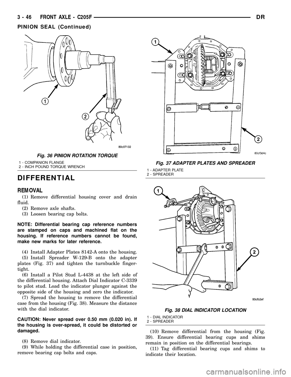
(4) Install Adapter Plates 8142-A onto the housing.
(5) Install Spreader W-129-B onto the adapter
plates (Fig. 37) and tighten the turnbuckle finger-
tight.
(6) Install a Pilot Stud L-4438 at the left side of
the differential housing. Attach Dial Indicator C-3339
to pilot stud. Load the indicator plunger against the
opposite side of the housing and zero the indicator.
(7) Spread the housing to remove the differential
case from the housing (Fig. 38). Measure the distance
with the dial indicator.
CAUTION: Never spread over 0.50 mm (0.020 in). If
the housing is over-spread, it could be distorted or
damaged.
(8) Remove dial indicator.
(9) While holding the differential case in position,
remove bearing cap bolts and caps.(10) Remove differential from the housing (Fig.
39). Ensure differential bearing cups and shims
remain in position on the differential bearings.
(11) Tag differential bearing cups and shims to
indicate their location.
Fig. 36 PINION ROTATION TORQUE
1 - COMPANION FLANGE
2 - INCH POUND TORQUE WRENCHFig. 37 ADAPTER PLATES AND SPREADER
1 - ADAPTER PLATE
2 - SPREADER
Fig. 38 DIAL INDICATOR LOCATION
1 - DIAL INDICATOR
2 - SPREADER
3 - 46 FRONT AXLE - C205FDR
PINION SEAL (Continued)
Page 153 of 2627
DIFFERENTIAL
REMOVAL
(1) Remove differential housing cover and drain
lubricant from the housing.
(2) Remove hub bearings and axle shafts.
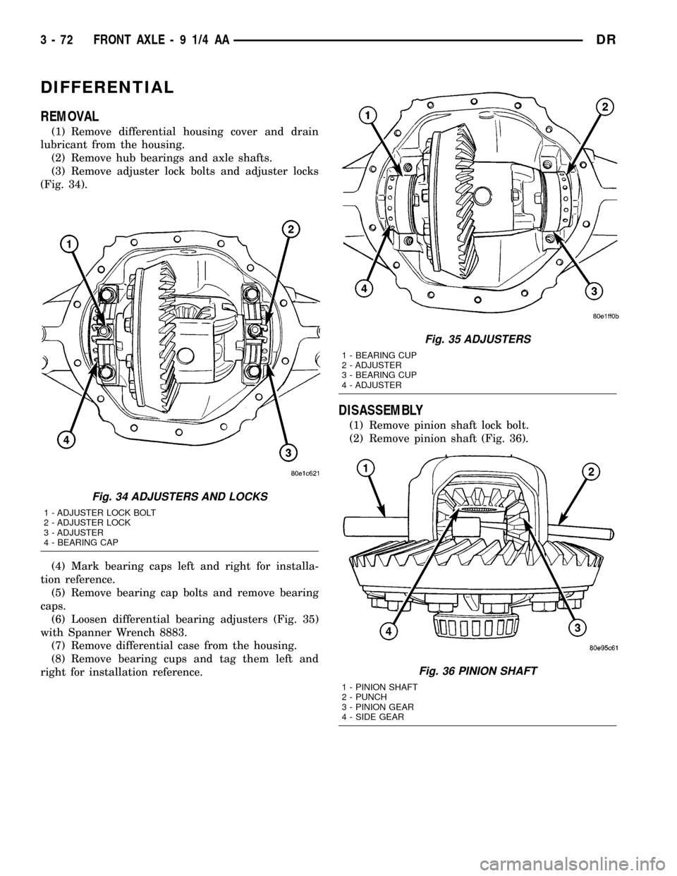
(3) Remove adjuster lock bolts and adjuster locks
(Fig. 34).
(4) Mark bearing caps left and right for installa-
tion reference.
(5) Remove bearing cap bolts and remove bearing
caps.
(6) Loosen differential bearing adjusters (Fig. 35)
with Spanner Wrench 8883.
(7) Remove differential case from the housing.
(8) Remove bearing cups and tag them left and
right for installation reference.
DISASSEMBLY
(1) Remove pinion shaft lock bolt.
(2) Remove pinion shaft (Fig. 36).
Fig. 34 ADJUSTERS AND LOCKS
1 - ADJUSTER LOCK BOLT
2 - ADJUSTER LOCK
3 - ADJUSTER
4 - BEARING CAP
Fig. 35 ADJUSTERS
1 - BEARING CUP
2 - ADJUSTER
3 - BEARING CUP
4 - ADJUSTER
Fig. 36 PINION SHAFT
1 - PINION SHAFT
2 - PUNCH
3 - PINION GEAR
4 - SIDE GEAR
3 - 72 FRONT AXLE - 9 1/4 AADR
Page 178 of 2627
(10) If rotating torque is low, use Holder 6719 to
hold the companion flange and tighten pinion nut in
6.8 N´m (5 ft. lbs.) increments until proper rotating
torque is achieved.
NOTE: The bearing rotating torque should be con-
stant during a complete revolution of the pinion. If
the rotating torque varies, this indicates a binding
condition.
NOTE: The seal replacement is unacceptable if the
final pinion nut torque is less than 285 N´m (210 ft.
lbs.).
(11) Install propeller shaft with the installation
reference marks aligned.
(12) Tighten the companion flange bolts to 108
N´m (80 ft. lbs.).
(13) Install brake rotors.
(14) Check the differential lubricant level.
DIFFERENTIAL COVER
REMOVAL
(1) With vehicle in neutral, position vehicle on
hoist.
(2) Remove drain plug.
(3) Remove cover bolts.
(4) Remove cover and drain lubricant.
INSTALLATION
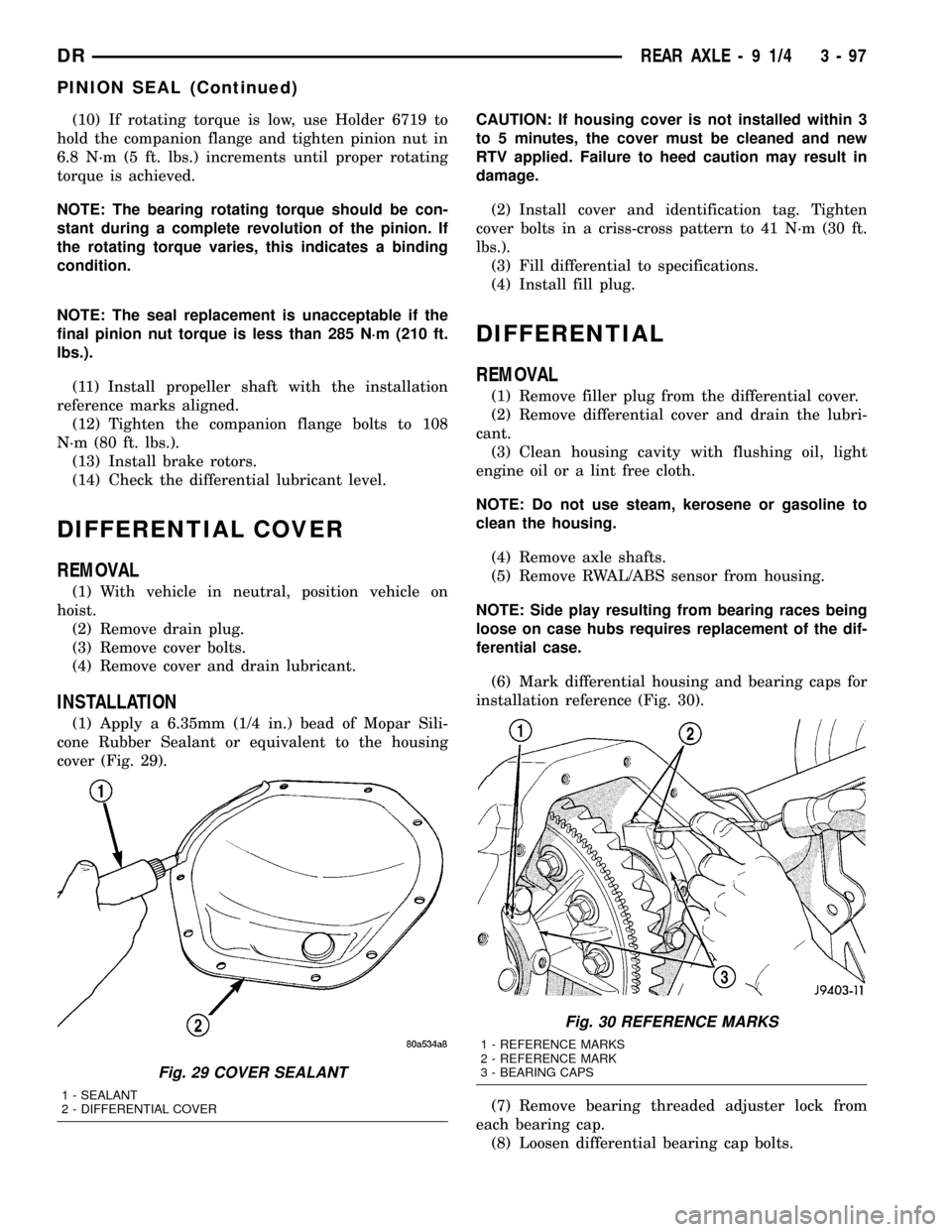
(1) Apply a 6.35mm (1/4 in.) bead of Mopar Sili-
cone Rubber Sealant or equivalent to the housing
cover (Fig. 29).CAUTION: If housing cover is not installed within 3
to 5 minutes, the cover must be cleaned and new
RTV applied. Failure to heed caution may result in
damage.
(2) Install cover and identification tag. Tighten
cover bolts in a criss-cross pattern to 41 N´m (30 ft.
lbs.).
(3) Fill differential to specifications.
(4) Install fill plug.
DIFFERENTIAL
REMOVAL
(1) Remove filler plug from the differential cover.
(2) Remove differential cover and drain the lubri-
cant.
(3) Clean housing cavity with flushing oil, light
engine oil or a lint free cloth.
NOTE: Do not use steam, kerosene or gasoline to
clean the housing.
(4) Remove axle shafts.
(5) Remove RWAL/ABS sensor from housing.
NOTE: Side play resulting from bearing races being
loose on case hubs requires replacement of the dif-
ferential case.
(6) Mark differential housing and bearing caps for
installation reference (Fig. 30).
(7) Remove bearing threaded adjuster lock from
each bearing cap.
(8) Loosen differential bearing cap bolts.
Fig. 29 COVER SEALANT
1 - SEALANT
2 - DIFFERENTIAL COVER
Fig. 30 REFERENCE MARKS
1 - REFERENCE MARKS
2 - REFERENCE MARK
3 - BEARING CAPS
DRREAR AXLE - 9 1/4 3 - 97
PINION SEAL (Continued)
Page 181 of 2627
CAUTION: If cover is not installed within 3 to 5 min-
utes, the cover must be cleaned and new RTV
applied or adhesion quality will be compromised.
(8) Install the cover and any identification tag and
tighten cover bolts to 41 N´m (30 ft. lbs.).
(9) Fill differential with lubricant to bottom of the
fill plug hole. Refer to the Lubricant Specifications
for the correct quantity and type.
NOTE: Trac-lokŸ differential equipped vehicles
should be road tested by making 10 to 12 slow fig-
ure-eight turns. This maneuver will pump the lubri-
cant through the clutch discs to eliminate a
possible chatter noise complaint.
DIFFERENTIAL-TRAC-LOK
DESCRIPTION
The optional Trac-Loktdifferential case has a one-
piece design and the similar internal components as
a standard differential, plus two clutch disc pack-
s.The differential pinion mate shaft is retained with
a threaded pin. Differential bearing preload and ring
gear backlash are set and maintained by threaded
adjusters at the outside of the differential housing.
Pinion bearing preload is set and maintained by the
use of a collapsible spacer. The removable differential
cover provides a means for inspection and service.
OPERATION
This differential clutches are engaged by two con-
current forces. The first being the preload force
exerted through Belleville spring washers within the
clutch packs. The second is the separating forces gen-
erated by the side gears as torque is applied through
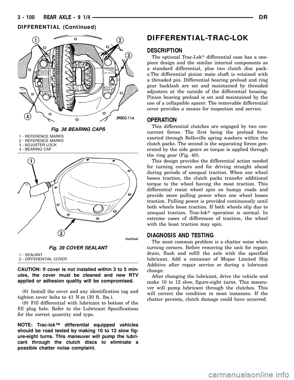
the ring gear (Fig. 40).
This design provides the differential action needed
for turning corners and for driving straight ahead
during periods of unequal traction. When one wheel
looses traction, the clutch packs transfer additional
torque to the wheel having the most traction. This
differential resist wheel spin on bumpy roads and
provide more pulling power when one wheel looses
traction. Pulling power is provided continuously until
both wheels loose traction. If both wheels slip due to
unequal traction, Trac-loktoperation is normal. In
extreme cases of differences of traction, the wheel
with the least traction may spin.
DIAGNOSIS AND TESTING
The most common problem is a chatter noise when
turning corners. Before removing the unit for repair,
drain, flush and refill the axle with the specified
lubricant. Add a container of Mopar Limited Slip
Additive after repair service or during a lubricant
change.
After changing the lubricant, drive the vehicle and
make 10 to 12 slow, figure-eight turns. This maneu-
ver will pump lubricant through the clutches. This
will correct the condition in most instances. If the
chatter persists, clutch damage could have occurred.
Fig. 38 BEARING CAPS
1 - REFERENCE MARKS
2 - REFERENCE MARKS
3 - ADJUSTER LOCK
4 - BEARING CAP
Fig. 39 COVER SEALANT
1 - SEALANT
2 - DIFFERENTIAL COVER
3 - 100 REAR AXLE-91/4DR
DIFFERENTIAL (Continued)
Page 208 of 2627
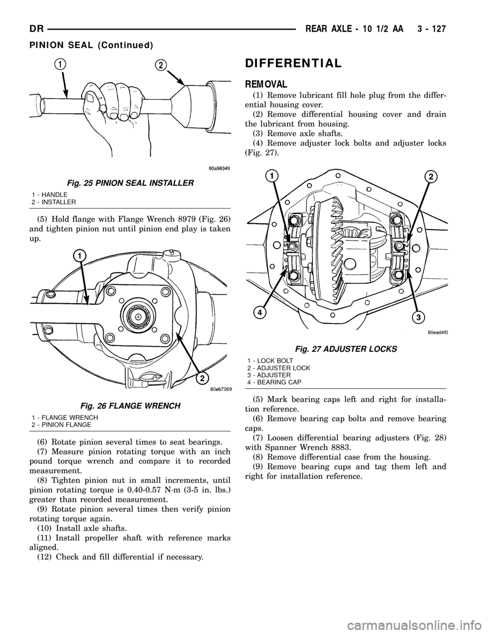
(5) Hold flange with Flange Wrench 8979 (Fig. 26)
and tighten pinion nut until pinion end play is taken
up.
(6) Rotate pinion several times to seat bearings.
(7) Measure pinion rotating torque with an inch
pound torque wrench and compare it to recorded
measurement.
(8) Tighten pinion nut in small increments, until
pinion rotating torque is 0.40-0.57 N´m (3-5 in. lbs.)
greater than recorded measurement.
(9) Rotate pinion several times then verify pinion
rotating torque again.
(10) Install axle shafts.
(11) Install propeller shaft with reference marks
aligned.
(12) Check and fill differential if necessary.
DIFFERENTIAL
REMOVAL
(1) Remove lubricant fill hole plug from the differ-
ential housing cover.
(2) Remove differential housing cover and drain
the lubricant from housing.
(3) Remove axle shafts.
(4) Remove adjuster lock bolts and adjuster locks
(Fig. 27).
(5) Mark bearing caps left and right for installa-
tion reference.
(6) Remove bearing cap bolts and remove bearing
caps.
(7) Loosen differential bearing adjusters (Fig. 28)
with Spanner Wrench 8883.
(8) Remove differential case from the housing.
(9) Remove bearing cups and tag them left and
right for installation reference.
Fig. 25 PINION SEAL INSTALLER
1 - HANDLE
2 - INSTALLER
Fig. 26 FLANGE WRENCH
1 - FLANGE WRENCH
2 - PINION FLANGE
Fig. 27 ADJUSTER LOCKS
1 - LOCK BOLT
2 - ADJUSTER LOCK
3 - ADJUSTER
4 - BEARING CAP
DRREAR AXLE - 10 1/2 AA 3 - 127
PINION SEAL (Continued)
Page 236 of 2627
DIFFERENTIAL
REMOVAL
(1) Remove fill hole plug from the differential
housing cover.
(2) Remove differential housing cover and drain
the lubricant.
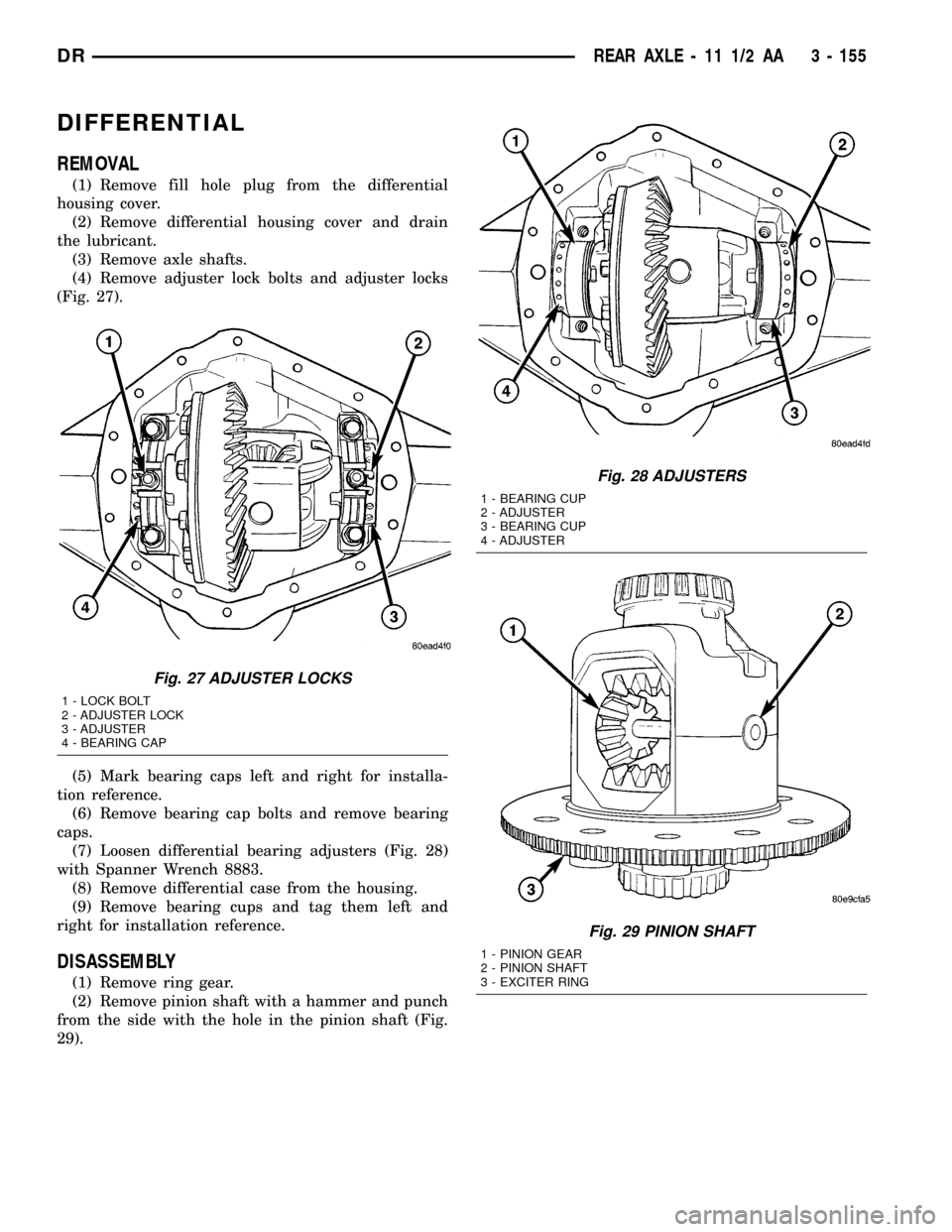
(3) Remove axle shafts.
(4) Remove adjuster lock bolts and adjuster locks
(Fig. 27).
(5) Mark bearing caps left and right for installa-
tion reference.
(6) Remove bearing cap bolts and remove bearing
caps.
(7) Loosen differential bearing adjusters (Fig. 28)
with Spanner Wrench 8883.
(8) Remove differential case from the housing.
(9) Remove bearing cups and tag them left and
right for installation reference.
DISASSEMBLY
(1) Remove ring gear.
(2) Remove pinion shaft with a hammer and punch
from the side with the hole in the pinion shaft (Fig.
29).
Fig. 27 ADJUSTER LOCKS
1 - LOCK BOLT
2 - ADJUSTER LOCK
3 - ADJUSTER
4 - BEARING CAP
Fig. 28 ADJUSTERS
1 - BEARING CUP
2 - ADJUSTER
3 - BEARING CUP
4 - ADJUSTER
Fig. 29 PINION SHAFT
1 - PINION GEAR
2 - PINION SHAFT
3 - EXCITER RING
DRREAR AXLE - 11 1/2 AA 3 - 155
Page 266 of 2627
rotor. At the same time, fluid pressure within the pis-
ton bore forces the caliper to slide inward on the
mounting bolts. This action brings the outboard
brake pad lining into contact with the outer surface
of the disc brake rotor.
In summary, fluid pressure acting simultaneously
on both piston and caliper, produces a strong clamp-
ing action. When sufficient force is applied, friction
will attempt to stop the rotors from turning and
bring the vehicle to a stop.
Application and release of the brake pedal gener-
ates only a very slight movement of the caliper and
piston. Upon release of the pedal, the caliper and pis-
ton return to a rest position. The brake pads do not
retract an appreciable distance from the rotor. In
fact, clearance is usually at, or close to zero. The rea-
sons for this are to keep road debris from getting
between the rotor and lining and in wiping the rotor
surface clear each revolution.
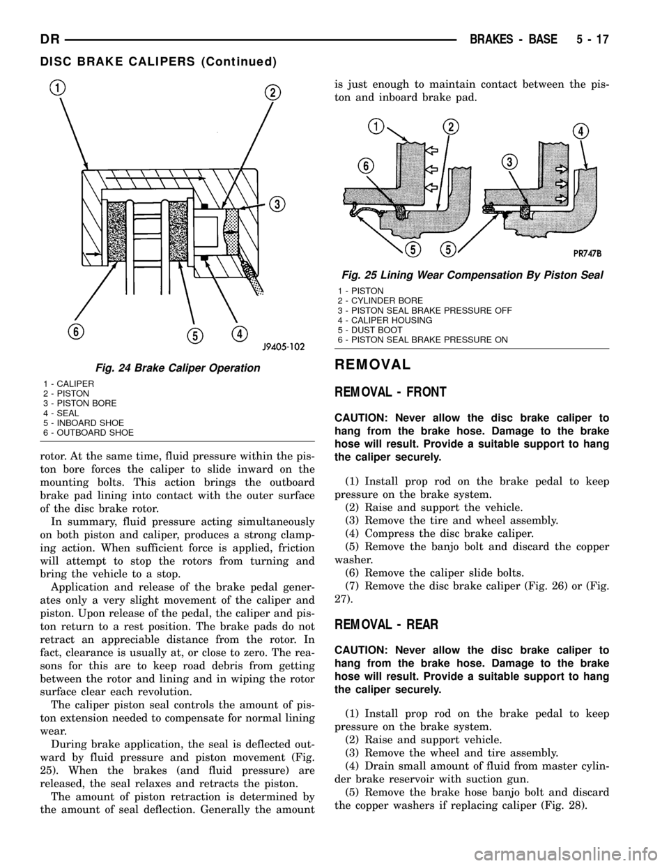
The caliper piston seal controls the amount of pis-
ton extension needed to compensate for normal lining
wear.
During brake application, the seal is deflected out-
ward by fluid pressure and piston movement (Fig.
25). When the brakes (and fluid pressure) are
released, the seal relaxes and retracts the piston.
The amount of piston retraction is determined by
the amount of seal deflection. Generally the amountis just enough to maintain contact between the pis-
ton and inboard brake pad.
REMOVAL
REMOVAL - FRONT
CAUTION: Never allow the disc brake caliper to
hang from the brake hose. Damage to the brake
hose will result. Provide a suitable support to hang
the caliper securely.
(1) Install prop rod on the brake pedal to keep
pressure on the brake system.
(2) Raise and support the vehicle.
(3) Remove the tire and wheel assembly.
(4) Compress the disc brake caliper.
(5) Remove the banjo bolt and discard the copper
washer.
(6) Remove the caliper slide bolts.
(7) Remove the disc brake caliper (Fig. 26) or (Fig.
27).
REMOVAL - REAR
CAUTION: Never allow the disc brake caliper to
hang from the brake hose. Damage to the brake
hose will result. Provide a suitable support to hang
the caliper securely.
(1) Install prop rod on the brake pedal to keep
pressure on the brake system.
(2) Raise and support vehicle.
(3) Remove the wheel and tire assembly.
(4) Drain small amount of fluid from master cylin-
der brake reservoir with suction gun.
(5) Remove the brake hose banjo bolt and discard
the copper washers if replacing caliper (Fig. 28).
Fig. 24 Brake Caliper Operation
1 - CALIPER
2 - PISTON
3 - PISTON BORE
4 - SEAL
5 - INBOARD SHOE
6 - OUTBOARD SHOE
Fig. 25 Lining Wear Compensation By Piston Seal
1 - PISTON
2 - CYLINDER BORE
3 - PISTON SEAL BRAKE PRESSURE OFF
4 - CALIPER HOUSING
5 - DUST BOOT
6 - PISTON SEAL BRAKE PRESSURE ON
DRBRAKES - BASE 5 - 17
DISC BRAKE CALIPERS (Continued)
Page 267 of 2627
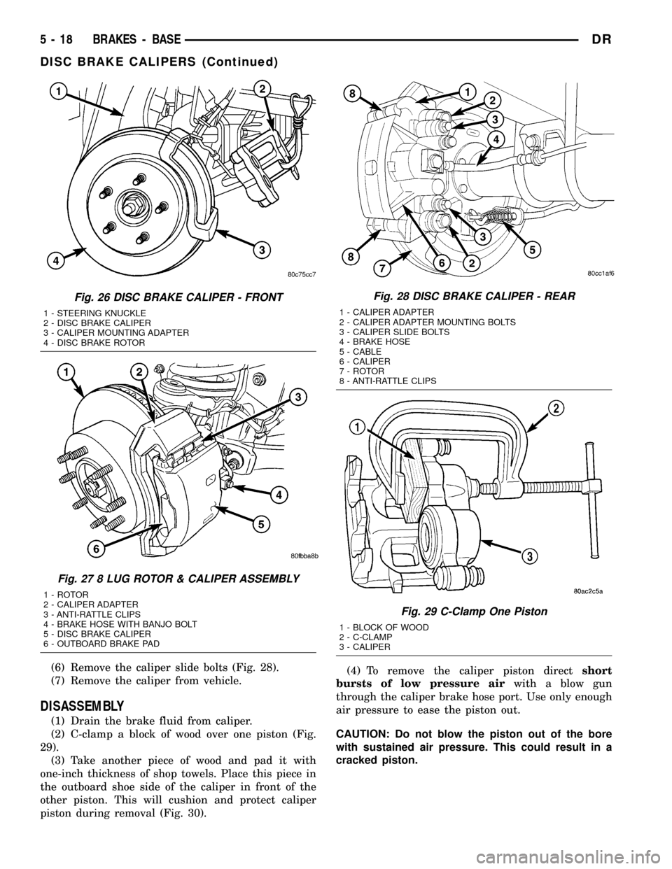
(6) Remove the caliper slide bolts (Fig. 28).
(7) Remove the caliper from vehicle.
DISASSEMBLY
(1) Drain the brake fluid from caliper.
(2) C-clamp a block of wood over one piston (Fig.
29).
(3) Take another piece of wood and pad it with
one-inch thickness of shop towels. Place this piece in
the outboard shoe side of the caliper in front of the
other piston. This will cushion and protect caliper
piston during removal (Fig. 30).(4) To remove the caliper piston directshort
bursts of low pressure airwith a blow gun
through the caliper brake hose port. Use only enough
air pressure to ease the piston out.
CAUTION: Do not blow the piston out of the bore
with sustained air pressure. This could result in a
cracked piston.
Fig. 26 DISC BRAKE CALIPER - FRONT
1 - STEERING KNUCKLE
2 - DISC BRAKE CALIPER
3 - CALIPER MOUNTING ADAPTER
4 - DISC BRAKE ROTOR
Fig. 27 8 LUG ROTOR & CALIPER ASSEMBLY
1 - ROTOR
2 - CALIPER ADAPTER
3 - ANTI-RATTLE CLIPS
4 - BRAKE HOSE WITH BANJO BOLT
5 - DISC BRAKE CALIPER
6 - OUTBOARD BRAKE PAD
Fig. 28 DISC BRAKE CALIPER - REAR
1 - CALIPER ADAPTER
2 - CALIPER ADAPTER MOUNTING BOLTS
3 - CALIPER SLIDE BOLTS
4 - BRAKE HOSE
5 - CABLE
6 - CALIPER
7 - ROTOR
8 - ANTI-RATTLE CLIPS
Fig. 29 C-Clamp One Piston
1 - BLOCK OF WOOD
2 - C-CLAMP
3 - CALIPER
5 - 18 BRAKES - BASEDR
DISC BRAKE CALIPERS (Continued)
Page 270 of 2627
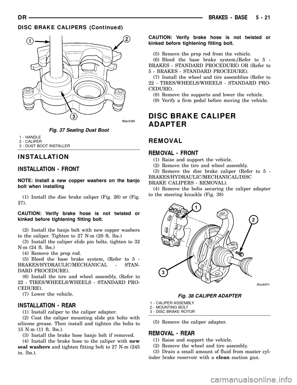
INSTALLATION
INSTALLATION - FRONT
NOTE: Install a new copper washers on the banjo
bolt when installing
(1) Install the disc brake caliper (Fig. 26) or (Fig.
27).
CAUTION: Verify brake hose is not twisted or
kinked before tightening fitting bolt.
(2) Install the banjo bolt with new copper washers
to the caliper. Tighten to 27 N´m (20 ft. lbs.)
(3) Install the caliper slide pin bolts. tighten to 32
N´m (24 ft. lbs.)
(4) Remove the prop rod.
(5) Bleed the base brake system, (Refer to 5 -
BRAKES/HYDRAULIC/MECHANICAL - STAN-
DARD PROCEDURE).
(6) Install the tire and wheel assembly, (Refer to
22 - TIRES/WHEELS/WHEELS - STANDARD PRO-
CEDURE).
(7) Lower the vehicle.
INSTALLATION - REAR
(1) Install caliper to the caliper adapter.
(2) Coat the caliper mounting slide pin bolts with
silicone grease. Then install and tighten the bolts to
15 N´m (11 ft. lbs.).
(3) Install the brake hose banjo bolt if removed.
(4) Install the brake hose to the caliper withnew
seal washersand tighten fitting bolt to 27 N´m (245
in. lbs.).CAUTION: Verify brake hose is not twisted or
kinked before tightening fitting bolt.
(5) Remove the prop rod from the vehicle.
(6) Bleed the base brake system,(Refer to 5 -
BRAKES - STANDARD PROCEDURE) OR (Refer to
5 - BRAKES - STANDARD PROCEDURE).
(7) Install the wheel and tire assemblies (Refer to
22 - TIRES/WHEELS/WHEELS - STANDARD PRO-
CEDURE).
(8) Remove the supports and lower the vehicle.
(9) Verify a firm pedal before moving the vehicle.
DISC BRAKE CALIPER
ADAPTER
REMOVAL
REMOVAL - FRONT
(1) Raise and support the vehicle.
(2) Remove the tire and wheel assembly.
(3) Remove the disc brake caliper (Refer to 5 -
BRAKES/HYDRAULIC/MECHANICAL/DISC
BRAKE CALIPERS - REMOVAL).
(4) Remove the bolts securing the caliper adapter
to the steering knuckle (Fig. 38)
(5) Remove the caliper adapter.
REMOVAL - REAR
(1) Raise and support the vehicle.
(2) Remove the wheel and tire assembly.
(3) Drain a small amount of fluid from master cyl-
inder brake reservoir with acleansuction gun.
Fig. 37 Seating Dust Boot
1 - HANDLE
2 - CALIPER
3 - DUST BOOT INSTALLER
Fig. 38 CALIPER ADAPTER
1 - CALIPER ASSEMBLY
2 - MOUNTING BOLT
3 - DISC BRAKE ROTOR
DRBRAKES - BASE 5 - 21
DISC BRAKE CALIPERS (Continued)
Page 272 of 2627
(3) Install parking brake cable in the brake lever.
(4) Install the park brake shoes (Refer to 5 -
BRAKES/PARKING BRAKE/SHOES - INSTALLA-
TION). (Fig. 66).
(5) Install axle shaft, (Refer to 3 - DIFFEREN-
TIAL & DRIVELINE/REAR AXLE - 9 1/4/AXLE
SHAFTS - INSTALLATION).
(6) Adjust brake shoes to drum with brake gauge
(Refer to 5 - BRAKES/PARKING BRAKE/SHOES -
ADJUSTMENTS).
(7) Install the rotor (Refer to 5 - BRAKES/HY-
DRAULIC/MECHANICAL/ROTORS - INSTALLA-
TION).
(8) Install the caliper adapter (Refer to 5 -
BRAKES/HYDRAULIC/MECHANICAL/DISC
BRAKE CALIPER ADAPTER - INSTALLATION).
(9) Install the caliper (Refer to 5 - BRAKES/HY-
DRAULIC/MECHANICAL/DISC BRAKE CALIPERS
- INSTALLATION).
(10) Install wheel and tire assembly.
FLUID
DIAGNOSIS AND TESTING - BRAKE FLUID
CONTAMINATION
Indications of fluid contamination are swollen or
deteriorated rubber parts.
Swollen rubber parts indicate the presence of
petroleum in the brake fluid.
To test for contamination, put a small amount of
drained brake fluid in clear glass jar. If fluid sepa-
rates into layers, there is mineral oil or other fluid
contamination of the brake fluid.
If brake fluid is contaminated, drain and thor-
oughly flush system. Replace master cylinder, propor-
tioning valve, caliper seals, wheel cylinder seals,
Antilock Brakes hydraulic unit and all hydraulic
fluid hoses.
STANDARD PROCEDURE - BRAKE FLUID
LEVEL
Always clean the master cylinder reservoir and
caps before checking fluid level. If not cleaned, dirt
could enter the fluid.
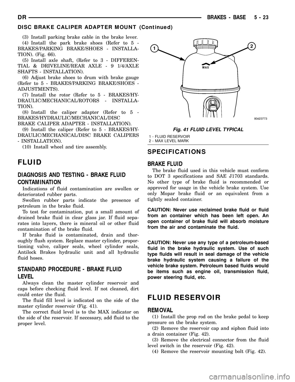
The fluid fill level is indicated on the side of the
master cylinder reservoir (Fig. 41).
The correct fluid level is to the MAX indicator on
the side of the reservoir. If necessary, add fluid to the
proper level.
SPECIFICATIONS
BRAKE FLUID
The brake fluid used in this vehicle must conform
to DOT 3 specifications and SAE J1703 standards.
No other type of brake fluid is recommended or
approved for usage in the vehicle brake system. Use
only Mopar brake fluid or an equivalent from a
tightly sealed container.
CAUTION: Never use reclaimed brake fluid or fluid
from an container which has been left open. An
open container of brake fluid will absorb moisture
from the air and contaminate the fluid.
CAUTION: Never use any type of a petroleum-based
fluid in the brake hydraulic system. Use of such
type fluids will result in seal damage of the vehicle
brake hydraulic system causing a failure of the
vehicle brake system. Petroleum based fluids would
be items such as engine oil, transmission fluid,
power steering fluid, etc.
FLUID RESERVOIR
REMOVAL
(1) Install the prop rod on the brake pedal to keep
pressure on the brake system.
(2) Remove the reservoir cap and siphon fluid into
a drain container (Fig. 42).
(3) Remove the electrical connector from the fluid
level switch in the reservoir (Fig. 42).
(4) Remove the reservoir mounting bolt (Fig. 42).
Fig. 41 FLUID LEVEL TYPICAL
1 - FLUID RESERVOIR
2 - MAX LEVEL MARK
DRBRAKES - BASE 5 - 23
DISC BRAKE CALIPER ADAPTER MOUNT (Continued)