spark plugs replace DODGE RAM 1500 1998 2.G Workshop Manual
[x] Cancel search | Manufacturer: DODGE, Model Year: 1998, Model line: RAM 1500, Model: DODGE RAM 1500 1998 2.GPages: 2627
Page 20 of 2627

²Trailer towing.
²Snowplowing.
²Heavy Loading.
²Taxi, police, or delivery service (commercial ser-
vice).
²Off-road or desert operation.
²If equipped for and operating with E-85
(ethanol) fuel.NOTE: If ANY of these apply to the vehicle then
change the engine oil every 3,000 miles (5 000 km)
or 3 months, whichever comes first and follow
schedule ªBº of the(Maintenance Schedules(sec-
tion of this manual.
If none of these apply to the vehicle, then change
the engine oil at every interval shown on schedule
(A(of the(Maintenance Schedules(section of this
manual.
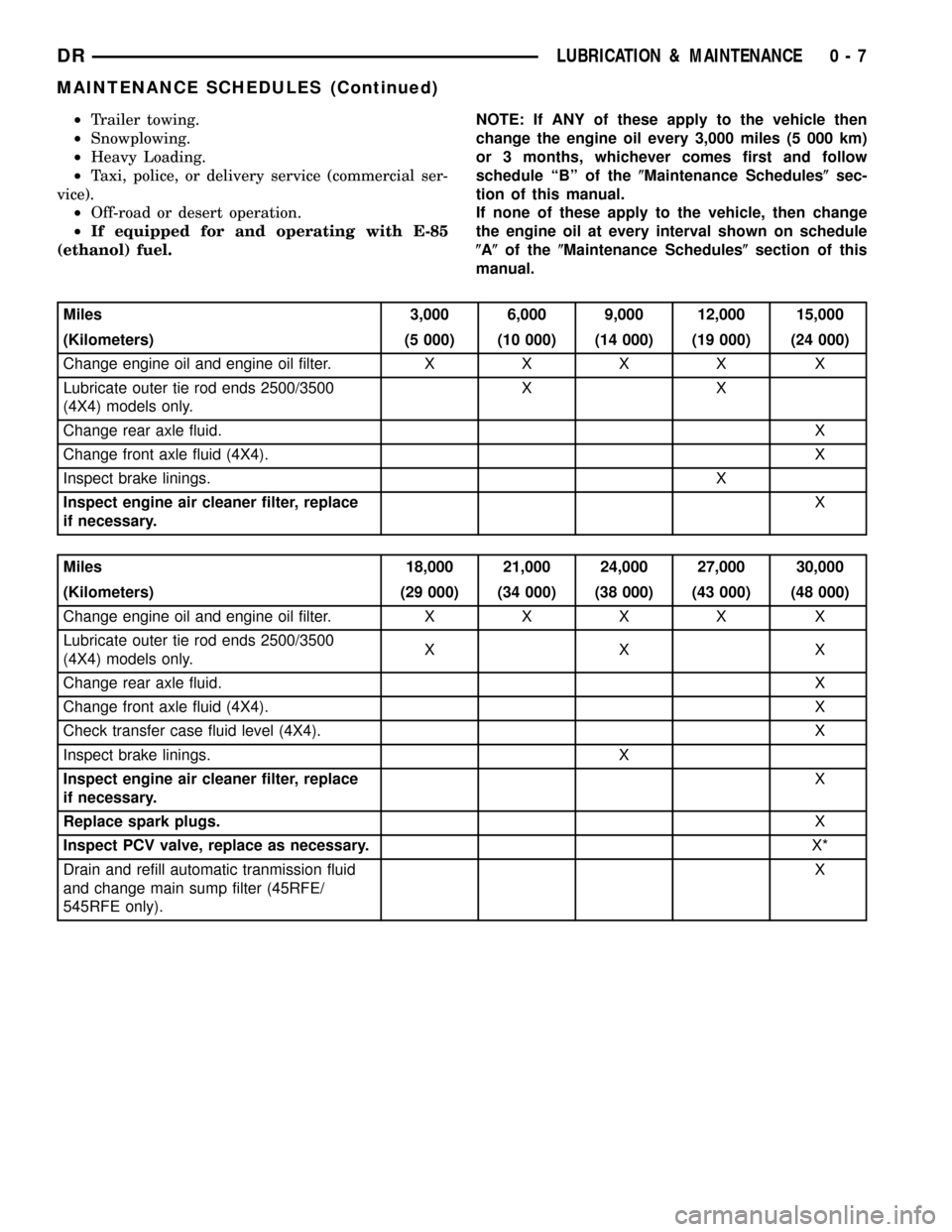
Miles 3,000 6,000 9,000 12,000 15,000
(Kilometers) (5 000) (10 000) (14 000) (19 000) (24 000)
Change engine oil and engine oil filter.XXXX X
Lubricate outer tie rod ends 2500/3500
(4X4) models only.XX
Change rear axle fluid.X
Change front axle fluid (4X4).X
Inspect brake linings.X
Inspect engine air cleaner filter, replace
if necessary.X
Miles 18,000 21,000 24,000 27,000 30,000
(Kilometers) (29 000) (34 000) (38 000) (43 000) (48 000)
Change engine oil and engine oil filter.XXXX X
Lubricate outer tie rod ends 2500/3500
(4X4) models only.XX X
Change rear axle fluid.X
Change front axle fluid (4X4).X
Check transfer case fluid level (4X4). X
Inspect brake linings. X
Inspect engine air cleaner filter, replace
if necessary.X
Replace spark plugs.X
Inspect PCV valve, replace as necessary.X*
Drain and refill automatic tranmission fluid
and change main sump filter (45RFE/
545RFE only).X
DRLUBRICATION & MAINTENANCE 0 - 7
MAINTENANCE SCHEDULES (Continued)
Page 21 of 2627

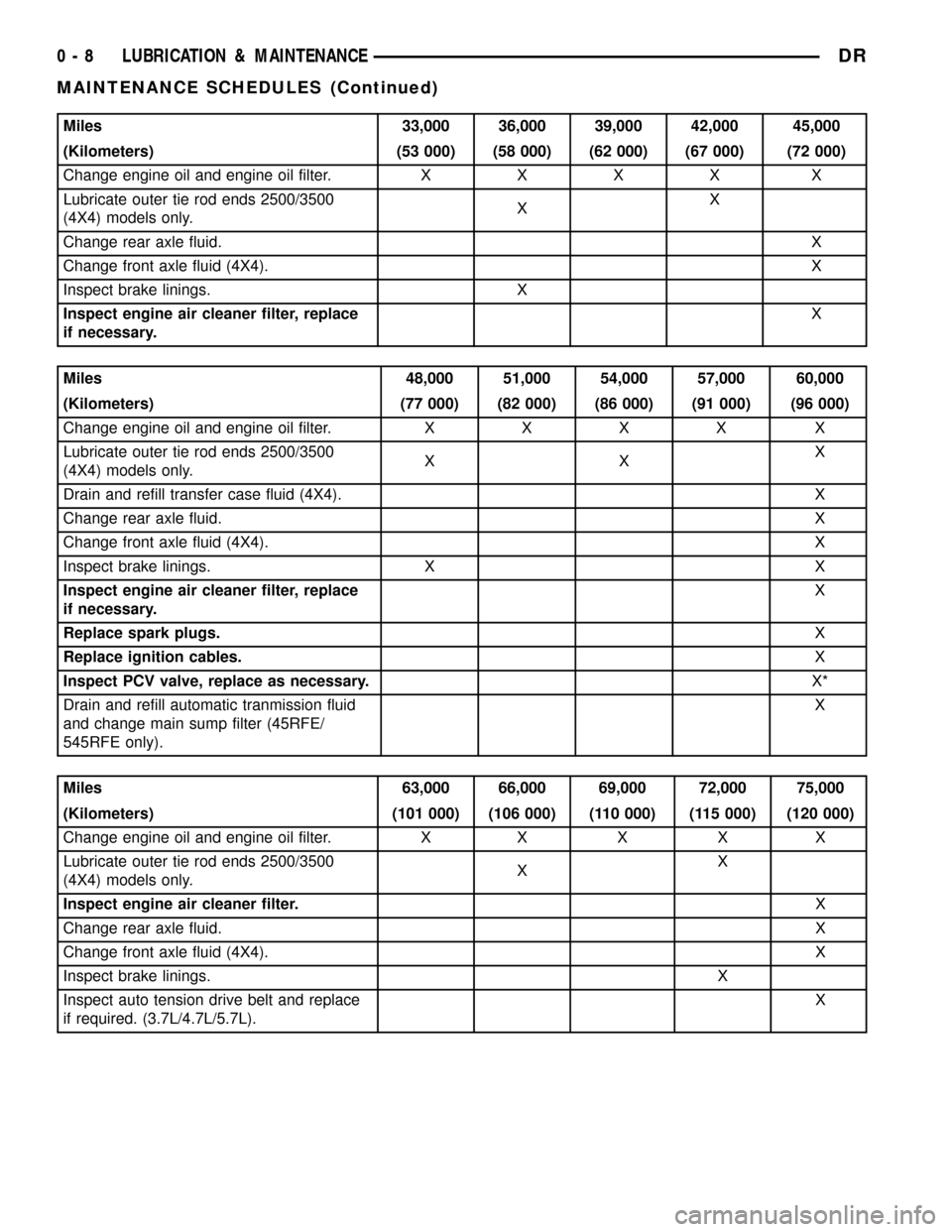
Miles 33,000 36,000 39,000 42,000 45,000
(Kilometers) (53 000) (58 000) (62 000) (67 000) (72 000)
Change engine oil and engine oil filter.XXXX X
Lubricate outer tie rod ends 2500/3500
(4X4) models only.XX
Change rear axle fluid.X
Change front axle fluid (4X4).X
Inspect brake linings. X
Inspect engine air cleaner filter, replace
if necessary.X
Miles 48,000 51,000 54,000 57,000 60,000
(Kilometers) (77 000) (82 000) (86 000) (91 000) (96 000)
Change engine oil and engine oil filter.XXXX X
Lubricate outer tie rod ends 2500/3500
(4X4) models only.XXX
Drain and refill transfer case fluid (4X4). X
Change rear axle fluid.X
Change front axle fluid (4X4).X
Inspect brake linings. X X
Inspect engine air cleaner filter, replace
if necessary.X
Replace spark plugs.X
Replace ignition cables.X
Inspect PCV valve, replace as necessary.X*
Drain and refill automatic tranmission fluid
and change main sump filter (45RFE/
545RFE only).X
Miles 63,000 66,000 69,000 72,000 75,000
(Kilometers) (101 000) (106 000) (110 000) (115 000) (120 000)
Change engine oil and engine oil filter. X X X X X
Lubricate outer tie rod ends 2500/3500
(4X4) models only.XX
Inspect engine air cleaner filter.X
Change rear axle fluid.X
Change front axle fluid (4X4).X
Inspect brake linings.X
Inspect auto tension drive belt and replace
if required. (3.7L/4.7L/5.7L).X
0 - 8 LUBRICATION & MAINTENANCEDR
MAINTENANCE SCHEDULES (Continued)
Page 22 of 2627

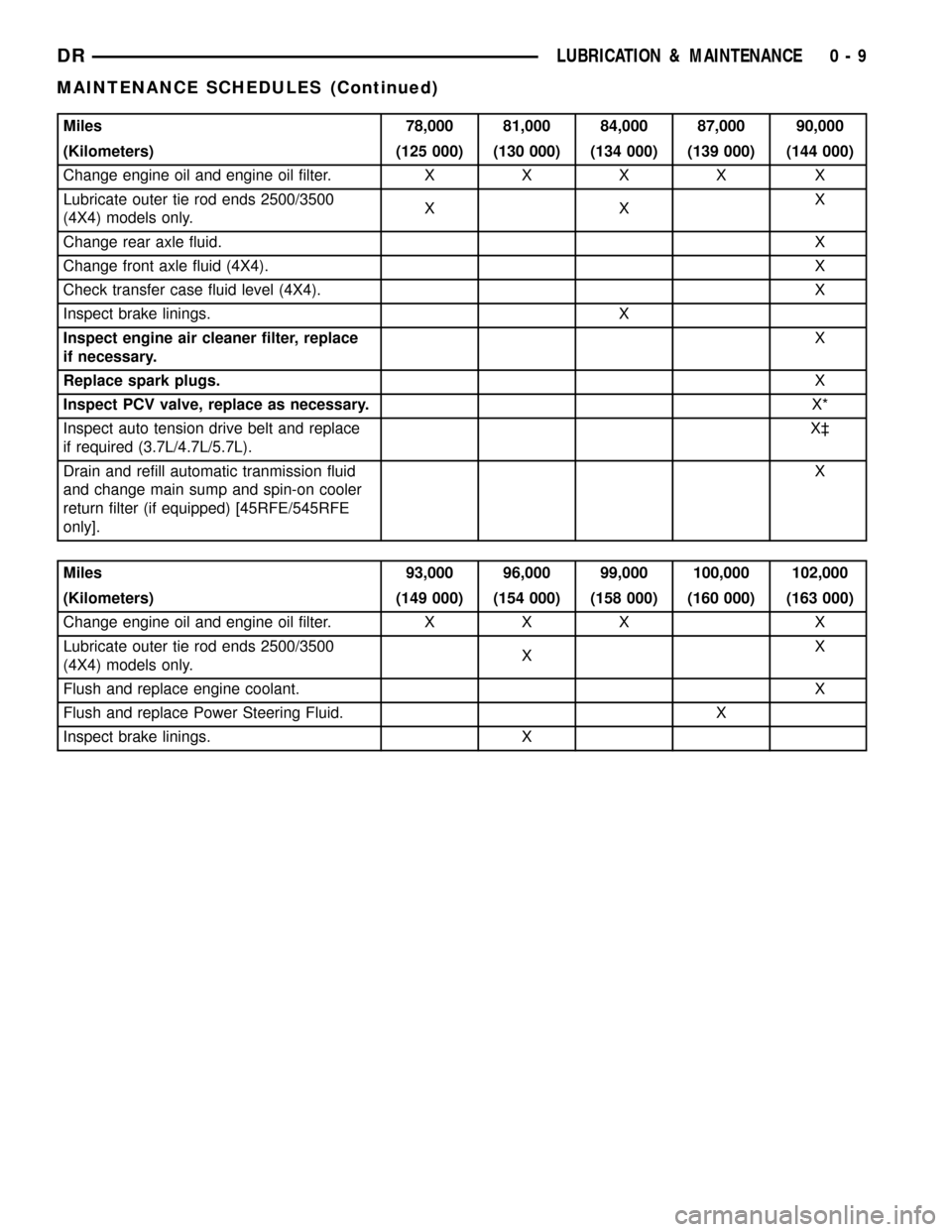
Miles 78,000 81,000 84,000 87,000 90,000
(Kilometers) (125 000) (130 000) (134 000) (139 000) (144 000)
Change engine oil and engine oil filter.XXXX X
Lubricate outer tie rod ends 2500/3500
(4X4) models only.XXX
Change rear axle fluid.X
Change front axle fluid (4X4).X
Check transfer case fluid level (4X4). X
Inspect brake linings. X
Inspect engine air cleaner filter, replace
if necessary.X
Replace spark plugs.X
Inspect PCV valve, replace as necessary.X*
Inspect auto tension drive belt and replace
if required (3.7L/4.7L/5.7L).X³
Drain and refill automatic tranmission fluid
and change main sump and spin-on cooler
return filter (if equipped) [45RFE/545RFE
only].X
Miles 93,000 96,000 99,000 100,000 102,000
(Kilometers) (149 000) (154 000) (158 000) (160 000) (163 000)
Change engine oil and engine oil filter. X X X X
Lubricate outer tie rod ends 2500/3500
(4X4) models only.XX
Flush and replace engine coolant.X
Flush and replace Power Steering Fluid. X
Inspect brake linings. X
DRLUBRICATION & MAINTENANCE 0 - 9
MAINTENANCE SCHEDULES (Continued)
Page 23 of 2627

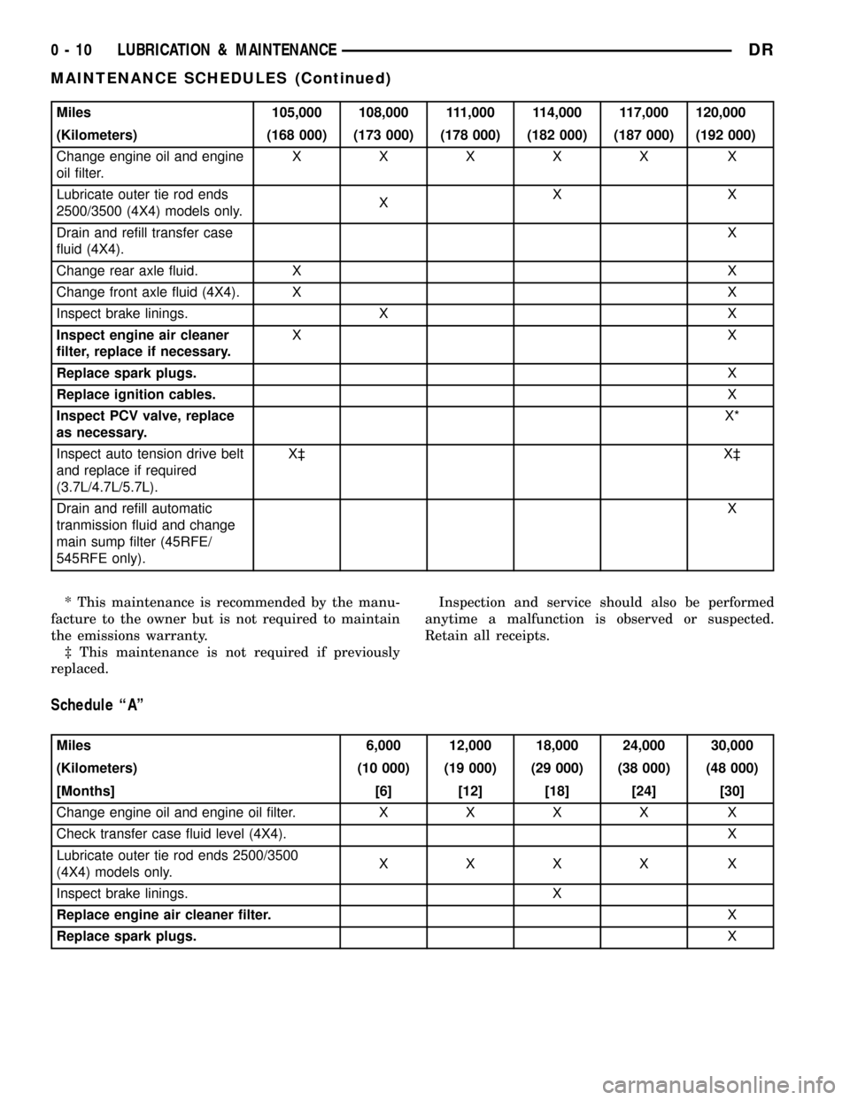
Miles 105,000 108,000 111,000 114,000 117,000 120,000
(Kilometers) (168 000) (173 000) (178 000) (182 000) (187 000) (192 000)
Change engine oil and engine
oil filter.XXXXX X
Lubricate outer tie rod ends
2500/3500 (4X4) models only.XXX
Drain and refill transfer case
fluid (4X4).X
Change rear axle fluid. X X
Change front axle fluid (4X4). X X
Inspect brake linings. X X
Inspect engine air cleaner
filter, replace if necessary.XX
Replace spark plugs.X
Replace ignition cables.X
Inspect PCV valve, replace
as necessary.X*
Inspect auto tension drive belt
and replace if required
(3.7L/4.7L/5.7L).X³ X³
Drain and refill automatic
tranmission fluid and change
main sump filter (45RFE/
545RFE only).X
* This maintenance is recommended by the manu-
facture to the owner but is not required to maintain
the emissions warranty.
³ This maintenance is not required if previously
replaced.Inspection and service should also be performed
anytime a malfunction is observed or suspected.
Retain all receipts.
Schedule ªAº
Miles 6,000 12,000 18,000 24,000 30,000
(Kilometers) (10 000) (19 000) (29 000) (38 000) (48 000)
[Months] [6] [12] [18] [24] [30]
Change engine oil and engine oil filter.XXXX X
Check transfer case fluid level (4X4). X
Lubricate outer tie rod ends 2500/3500
(4X4) models only.XXXX X
Inspect brake linings. X
Replace engine air cleaner filter.X
Replace spark plugs.X
0 - 10 LUBRICATION & MAINTENANCEDR
MAINTENANCE SCHEDULES (Continued)
Page 24 of 2627
![DODGE RAM 1500 1998 2.G Workshop Manual Miles 36,000 42,000 48,000 54,000 60,000 66,000
(Kilometers) (58 000) (67 000) (77 000) (84 000) (96 000) (106 000)
[Months] [36] [42] [48] [54] [60] [66]
Change engine oil and engine
oil filter.XXXXX DODGE RAM 1500 1998 2.G Workshop Manual Miles 36,000 42,000 48,000 54,000 60,000 66,000
(Kilometers) (58 000) (67 000) (77 000) (84 000) (96 000) (106 000)
[Months] [36] [42] [48] [54] [60] [66]
Change engine oil and engine
oil filter.XXXXX](/img/12/5702/w960_5702-23.png)
Miles 36,000 42,000 48,000 54,000 60,000 66,000
(Kilometers) (58 000) (67 000) (77 000) (84 000) (96 000) (106 000)
[Months] [36] [42] [48] [54] [60] [66]
Change engine oil and engine
oil filter.XXXXX
X
Check transfer case fluid level
(4X4).X
Lubricate outer tie rod ends
2500/3500 (4X4) models only.XXXXX X
Flush and replace engine
coolant at 60 months,
regardless of mileage.X
Inspect brake linings. X X
Replace engine air cleaner
filter.X
Replace spark plugs.X
Inspect PCV valve, replace
as necessary.X*
Replace ignition cables.X
Miles 72,000 78,000 84,000 90,000 96,000 100,000
(Kilometers) (115000) (125 000) (134 000) (144 000) (154 000) 160 000
[Months] [72] [78] [84] [90] [96]
Change engine oil and engine
oil filter.XXXXX
Lubricate outer tie rod ends
2500/3500 (4X4) models only.XXXXX
Check transfer case fluid level
(4X4).X
Flush and replace Power
Steering Fluid.X
Inspect brake linings. X X
Replace engine air cleaner
filter.X
Replace spark plugs.X
Inspect PCV valve, replace
as necessary.X*
Inspect auto tension drive belt
and replace if required
(3.7L/4.7L/5.7L).X
Drain and refill automatic
tranmission fluid and change
main sump filter and spin-on
cooler return filter (if
equipped) [45RFE/545RFE
only].X
DRLUBRICATION & MAINTENANCE 0 - 11
MAINTENANCE SCHEDULES (Continued)
Page 25 of 2627
![DODGE RAM 1500 1998 2.G Workshop Manual Miles 102,000 108,000 114,000 120,000
(Kilometers) (163 000) (173 000) (182 000) (192 000)
[Months] [102] [108] [114] [120]
Change engine oil and engine oil filter. X X X X
Drain and refill transfer c DODGE RAM 1500 1998 2.G Workshop Manual Miles 102,000 108,000 114,000 120,000
(Kilometers) (163 000) (173 000) (182 000) (192 000)
[Months] [102] [108] [114] [120]
Change engine oil and engine oil filter. X X X X
Drain and refill transfer c](/img/12/5702/w960_5702-24.png)
Miles 102,000 108,000 114,000 120,000
(Kilometers) (163 000) (173 000) (182 000) (192 000)
[Months] [102] [108] [114] [120]
Change engine oil and engine oil filter. X X X X
Drain and refill transfer case fluid (4X4). X
Flush and replace engine coolant, if not done at 60 mos. X
Lubricate outer tie rod ends 2500/3500 (4X4) models
only.XXX X
Inspect brake linings. X
Inspect auto tension drive belt and replace if required
(3.7L/4.7L/5.7L).X³X³
Replace ignition cables.X
Replace engine air cleaner filter.X
Replace spark plugs.X
Inspect PCV Valve, replace as necessary X*
* This maintenance is recommended by the manu-
facture to the owner but is not required to maintain
the emissions warranty.
³ This maintenance is not required if previously
replaced.
Inspection and service should also be performed
anytime a malfunction is observed or suspected.
WARNING: You can be badly injured working on or
around a motor vehicle. Do only that service work
for which you have the knowledge and the right
equipment. If you have any doubt about your ability
to perform a service job, take your vehicle to a
competent mechanic.
MAINTENANCE SCHEDULES Ð 24±VALVE
CUMMINS TURBO DIESEL
There are two maintenance schedules that show
therequiredservice for your vehicle.
First is ScheduleªBº. It is for vehicles that are
operated under the conditions that are listed below
and at the beginning of the schedule.
²Day or night temperatures are below 0É C (32É
F).
²Stop and go driving.
²Extensive engine idling.
²Driving in dusty conditions.
²Short trips of less than 16 km (10 miles).
²More than 50% of your driving is at sustained
high speeds during hot weather, above 32É C (90É F).²Trailer towing.
²Taxi, police, or delivery service (commercial ser-
vice).
²Off-road or desert operation.
NOTE: Most vehicles are operated under the condi-
tions listed for Schedule(B(.
Second is ScheduleªAº. It is for vehicles that are
not operated under any of the conditions listed under
Schedule9B9.
Use the schedule that best describes your driving
conditions. Where time and mileage are listed, follow
the interval that occurs first.
CAUTION: Failure to perform the required mainte-
nance items may result in damage to the vehicle.At Each Stop for Fuel
²Check the engine oil level about 15 minutes
after a fully warmed engine is shut off. Checking the
oil level while the vehicle is on level ground will
improve the accuracy of the oil level reading. Add oil
only when the level is at or below the ADD or MIN
mark.
²Check the windshield washer solvent and add if
required.
²Drain water from the fuel filter.
0 - 12 LUBRICATION & MAINTENANCEDR
MAINTENANCE SCHEDULES (Continued)
Page 501 of 2627

(4) Remove coil mounting nut from mounting stud
(Fig. 17).
(5) Carefully pull up coil from cylinder head open-
ing with a slight twisting action.
(6) Remove coil from vehicle.
5.7L V-8
Before removing or disconnecting any spark plug
cables, note their original position. Remove cables
one-at-a-time. To prevent ignition crossfire, spark
plug cablesMUSTbe placed in cable tray (routing
loom) into their original position.
An individual ignition coil (Fig. 18) is used at each
cylinder. The coil mounts to the top of the valve cover
with 2 bolts (Fig. 19). The bottom of the coil is
equipped with a rubber boot to seal the spark plug to
the coil. Inside each rubber boot is a spring. The
spring is used for a mechanical contact between the
coil and the top of the spark plug.
(1) Depending on which coil is being removed, the
throttle body air intake tube or intake box may need
to be removed to gain access to coil.
(2) Unlock electrical connector (Fig. 19) by moving
slide lock first. Press on release lock (Fig. 19) while
pulling electrical connector from coil.
(3) Disconnect secondary high-voltage cable from
coil with a twisting action.
(4) Clean area at base of coil with compressed air
before removal.
(5) Remove 2 mounting bolts (note that mounting
bolts are retained to coil).
(6) Carefully pull up coil from cylinder head open-
ing with a slight twisting action.
(7) Remove coil from vehicle.
(8) Before installing spark plug cables to either the
spark plugs or coils, or before installing a coil to a
spark plug, apply dielectric grease to inside of boots.
INSTALLATION
3.7L V-6
(1) Using compressed air, blow out any dirt or con-
taminants from around top of spark plug.
(2) Check condition of coil o-ring and replace as
necessary. To aid in coil installation, apply silicone to
coil o-ring.
(3) Position ignition coil into cylinder head opening
and push onto spark plug. Do this while guiding coil
base over mounting stud.
(4) Install coil mounting stud nut. Refer to torque
specifications.
(5) Connect electrical connector to coil by snapping
into position.
(6) If necessary, install throttle body air tube.
4.7L V-8
(1) Using compressed air, blow out any dirt or con-
taminants from around top of spark plug.
(2) Check condition of coil o-ring and replace as
necessary. To aid in coil installation, apply silicone to
coil o-ring.
(3) Position ignition coil into cylinder head opening
and push onto spark plug. Do this while guiding coil
base over mounting stud.
(4) Install coil mounting stud nut. Refer to torque
specifications.
(5) Connect electrical connector to coil by snapping
into position.
(6) If necessary, install throttle body air tube.
5.7L V-8
(1) Using compressed air, blow out any dirt or con-
taminants from around top of spark plug.
(2) Before installing spark plug cables to either the
spark plugs or coils, or before installing a coil to a
spark plug, apply dielectric grease to inside of boots.
(3) Position ignition coil into cylinder head opening
and push onto spark plug. Twist coil into position.
(4) Install 2 coil mounting bolts. Refer to torque
specifications.
(5) Connect electrical connector to coil by snapping
into position.
(6) Install cable to coil. To prevent ignition cross-
fire, spark plug cablesMUSTbe placed in cable tray
(routing loom) into their original position. Refer to
Spark Plug Cable Removal for a graphic.
(7) If necessary, install throttle body air tube.
KNOCK SENSOR
DESCRIPTION
The sensors are used only with 3.7L V-6, 4.7L V-8
and 5.7L V-8 engines. On 3.7L V-6 and 4.7L V-8
engines, the 2 knock sensors are bolted into the cyl-
inder block under the intake manifold.
On 5.7L V-8 engines, 2 knock sensors are also
used. These are bolted into each side of the cylinder
block (outside) under the exhaust manifold.
OPERATION
3.7L V-6 / 4.7L V-8 / 5.7L V-8 Engines Only
Two knock sensors are used; one for each cylinder
bank. When the knock sensor detects a knock in one
of the cylinders on the corresponding bank, it sends
an input signal to the Powertrain Control Module
(PCM). In response, the PCM retards ignition timing
for all cylinders by a scheduled amount.
8I - 14 IGNITION CONTROLDR
IGNITION COIL (Continued)
Page 504 of 2627

SPARK PLUG
DESCRIPTION
Resistor type spark plugs are used on all engines.
Sixteen spark plugs (2 per cylinder) are used with
5.7L V-8 engines.
DIAGNOSIS AND TESTING - SPARK PLUG
CONDITIONS
To prevent possible pre-ignition and/or mechanical
engine damage, the correct type/heat range/number
spark plug must be used.
Always use the recommended torque when tighten-
ing spark plugs. Incorrect torque can distort the
spark plug and change plug gap. It can also pull the
plug threads and do possible damage to both the
spark plug and the cylinder head.
Remove the spark plugs and examine them for
burned electrodes and fouled, cracked or broken por-
celain insulators. Keep plugs arranged in the order
in which they were removed from the engine. A sin-
gle plug displaying an abnormal condition indicates
that a problem exists in the corresponding cylinder.
Replace spark plugs at the intervals recommended in
the Lubrication and Maintenance section.
Spark plugs that have low mileage may be cleaned
and reused if not otherwise defective, carbon or oil
fouled.
CAUTION: Never use a motorized wire wheel brush
to clean the spark plugs. Metallic deposits will
remain on the spark plug insulator and will cause
plug misfire.
Spark plug resistance values range from 6,000 to
20,000 ohms (when checked with at least a 1000 volt
spark plug tester).Do not use an ohmmeter to
check the resistance values of the spark plugs.
Inaccurate readings will result.
NORMAL OPERATING
The few deposits present on the spark plug will
probably be light tan or slightly gray in color. This is
evident with most grades of commercial gasoline
(Fig. 23). There will not be evidence of electrode
burning. Gap growth will not average more than
approximately 0.025 mm (.001 in) per 3200 km (2000
miles) of operation. Spark plugs that have normal
wear can usually be cleaned, have the electrodes
filed, have the gap set and then be installed.Some fuel refiners in several areas of the United
States have introduced a manganese additive (MMT)
for unleaded fuel. During combustion, fuel with MMT
causes the entire tip of the spark plug to be coated
with a rust colored deposit. This rust color can be
misdiagnosed as being caused by coolant in the com-
bustion chamber. Spark plug performance may be
affected by MMT deposits.
COLD FOULING/CARBON FOULING
Cold fouling is sometimes referred to as carbon
fouling. The deposits that cause cold fouling are basi-
cally carbon (Fig. 23). A dry, black deposit on one or
two plugs in a set may be caused by sticking valves
or defective spark plug cables. Cold (carbon) fouling
of the entire set of spark plugs may be caused by a
clogged air cleaner element or repeated short operat-
ing times (short trips).
WET FOULING OR GAS FOULING
A spark plug coated with excessive wet fuel or oil
is wet fouled. In older engines, worn piston rings,
leaking valve guide seals or excessive cylinder wear
can cause wet fouling. In new or recently overhauled
engines, wet fouling may occur before break-in (nor-
mal oil control) is achieved. This condition can usu-
ally be resolved by cleaning and reinstalling the
fouled plugs.
OIL OR ASH ENCRUSTED
If one or more spark plugs are oil or oil ash
encrusted (Fig. 24), evaluate engine condition for the
cause of oil entry into that particular combustion
chamber.
Fig. 23 NORMAL OPERATION AND COLD (CARBON)
FOULING
1 - NORMAL
2 - DRY BLACK DEPOSITS
3 - COLD (CARBON) FOULING
DRIGNITION CONTROL 8I - 17
Page 505 of 2627

ELECTRODE GAP BRIDGING
Electrode gap bridging may be traced to loose
deposits in the combustion chamber. These deposits
accumulate on the spark plugs during continuous
stop-and-go driving. When the engine is suddenly
subjected to a high torque load, deposits partially liq-
uefy and bridge the gap between electrodes (Fig. 25).
This short circuits the electrodes. Spark plugs with
electrode gap bridging can be cleaned using standard
procedures.
SCAVENGER DEPOSITS
Fuel scavenger deposits may be either white or yel-
low (Fig. 26). They may appear to be harmful, but
this is a normal condition caused by chemical addi-
tives in certain fuels. These additives are designed to
change the chemical nature of deposits and decrease
spark plug misfire tendencies. Notice that accumula-
tion on the ground electrode and shell area may be
heavy, but the deposits are easily removed. Spark
plugs with scavenger deposits can be considered nor-
mal in condition and can be cleaned using standard
procedures.
CHIPPED ELECTRODE INSULATOR
A chipped electrode insulator usually results from
bending the center electrode while adjusting the
spark plug electrode gap. Under certain conditions,
severe detonation can also separate the insulator
from the center electrode (Fig. 27). Spark plugs with
this condition must be replaced.
PREIGNITION DAMAGE
Preignition damage is usually caused by excessive
combustion chamber temperature. The center elec-
trode dissolves first and the ground electrode dis-
solves somewhat latter (Fig. 28). Insulators appear
relatively deposit free. Determine if the spark plug
has the correct heat range rating for the engine.
Determine if ignition timing is over advanced or if
other operating conditions are causing engine over-
heating. (The heat range rating refers to the operat-
ing temperature of a particular type spark plug.
Spark plugs are designed to operate within specific
temperature ranges. This depends upon the thick-
ness and length of the center electrodes porcelain
insulator.)
Fig. 24 OIL OR ASH ENCRUSTED
Fig. 25 ELECTRODE GAP BRIDGING
1 - GROUND ELECTRODE
2 - DEPOSITS
3 - CENTER ELECTRODE
Fig. 26 SCAVENGER DEPOSITS
1 - GROUND ELECTRODE COVERED WITH WHITE OR YELLOW
DEPOSITS
2 - CENTER ELECTRODE
8I - 18 IGNITION CONTROLDR
SPARK PLUG (Continued)
Page 506 of 2627

SPARK PLUG OVERHEATING
Overheating is indicated by a white or gray center
electrode insulator that also appears blistered (Fig.
29). The increase in electrode gap will be consider-
ably in excess of 0.001 inch per 2000 miles of opera-
tion. This suggests that a plug with a cooler heat
range rating should be used. Over advanced ignition
timing, detonation and cooling system malfunctions
can also cause spark plug overheating.
REMOVAL
3.7L V-6
Each individual spark plug is located under each
ignition coil. Each individual ignition coil must be
removed to gain access to each spark plug. Refer to
Ignition Coil Removal/Installation.(1) Remove necessary air filter tubing at throttle
body.
(2) Prior to removing ignition coil, spray com-
pressed air around coil base at cylinder head.
(3) Prior to removing spark plug, spray com-
pressed air into cylinder head opening. This will help
prevent foreign material from entering combustion
chamber.
(4) Remove spark plug from cylinder head using a
quality socket with a rubber or foam insert. Also
check condition of ignition coil o-ring and replace as
necessary.
(5) Inspect spark plug condition. Refer to Diagnos-
tics and Testing - Spark Plug Conditions.
4.7L V-8
Each individual spark plug is located under each
ignition coil. Each individual ignition coil must be
removed to gain access to each spark plug. Refer to
Ignition Coil Removal/Installation.
(1) Remove necessary air filter tubing at throttle
body.
(2) Prior to removing ignition coil, spray com-
pressed air around coil base at cylinder head.
(3) Prior to removing spark plug, spray com-
pressed air into cylinder head opening. This will help
prevent foreign material from entering combustion
chamber.
(4) Remove spark plug from cylinder head using a
quality socket with a rubber or foam insert. Also
check condition of ignition coil o-ring and replace as
necessary.
(5) Inspect spark plug condition. Refer to Diagnos-
tics and Testing - Spark Plug Conditions.
5.7L V-8
Eight of the 16 spark plugs are located under an
ignition coil; the other 8 are not. If spark plug being
Fig. 27 CHIPPED ELECTRODE INSULATOR
1 - GROUND ELECTRODE
2 - CENTER ELECTRODE
3 - CHIPPED INSULATOR
Fig. 28 PREIGNITION DAMAGE
1 - GROUND ELECTRODE STARTING TO DISSOLVE
2 - CENTER ELECTRODE DISSOLVED
Fig. 29 SPARK PLUG OVERHEATING
1 - BLISTERED WHITE OR GRAY COLORED INSULATOR
DRIGNITION CONTROL 8I - 19
SPARK PLUG (Continued)