table of contents DODGE RAM 1500 1998 2.G Workshop Manual
[x] Cancel search | Manufacturer: DODGE, Model Year: 1998, Model line: RAM 1500, Model: DODGE RAM 1500 1998 2.GPages: 2627
Page 2 of 2627
INTRODUCTION
TABLE OF CONTENTS
page page
VEHICLE IDENTIFICATION NUMBER
DESCRIPTION..........................1
VEHICLE EMISSION CONTROL INFORMATION
(VECI)
DESCRIPTION..........................2
BODY CODE PLATE
DESCRIPTION..........................3
INTERNATIONAL VEHICLE CONTROL &
DISPLAY SYMBOLS
DESCRIPTION - INTERNATIONAL SYMBOLS . . . 5
FASTENER IDENTIFICATION
DESCRIPTION..........................5FASTENER USAGE
DESCRIPTION - FASTENER USAGE.........8
THREADED HOLE REPAIR
DESCRIPTION - THREADED HOLE REPAIR....8
METRIC SYSTEM
DESCRIPTION..........................8
TORQUE REFERENCES
DESCRIPTION.........................10
VEHICLE CERTIFICATION LABEL
DESCRIPTION.........................11
VEHICLE IDENTIFICATION
NUMBER
DESCRIPTION
VIN CODING/LOCATIONS
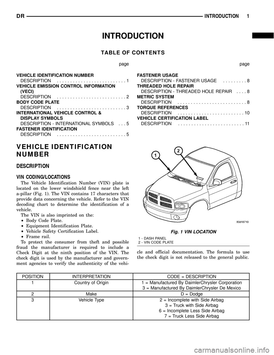
The Vehicle Identification Number (VIN) plate is
located on the lower windshield fence near the left
a-pillar (Fig. 1). The VIN contains 17 characters that
provide data concerning the vehicle. Refer to the VIN
decoding chart to determine the identification of a
vehicle.
The VIN is also imprinted on the:
²Body Code Plate.
²Equipment Identification Plate.
²Vehicle Safety Certification Label.
²Frame rail.
To protect the consumer from theft and possible
fraud the manufacturer is required to include a
Check Digit at the ninth position of the VIN. The
check digit is used by the manufacturer and govern-
ment agencies to verify the authenticity of the vehi-cle and official documentation. The formula to use
the check digit is not released to the general public.
POSITION INTERPRETATION CODE = DESCRIPTION
1 Country of Origin 1 = Manufactured By DaimlerChrysler Corporation
3 = Manufactured By DaimlerChrysler De Mexico
2 Make D = Dodge
3 Vehicle Type 2 = Incomplete with Side Airbag
3 = Truck with Side Airbag
6 = Incomplete Less Side Airbag
7 = Truck Less Side Airbag
Fig. 1 VIN LOCATION
1 - DASH PANEL
2 - VIN CODE PLATE
DRINTRODUCTION 1
Page 14 of 2627
LUBRICATION & MAINTENANCE
TABLE OF CONTENTS
page page
FLUID TYPES
DESCRIPTION
DESCRIPTION - FUEL REQUIREMENTS -
DIESEL ENGINE.......................1
DESCRIPTION - ENGINE OIL AND
LUBRICANTS.........................1
DESCRIPTION - ENGINE OIL - DIESEL
ENGINES............................2
DESCRIPTION - POWER STEERING FLUID . . 3
DESCRIPTION - ENGINE COOLANT........3
DESCRIPTION - TRANSFER CASE.........4
DESCRIPTION - AXLE...................4
DESCRIPTION - MANUAL TRANSMISSION . . . 4
DESCRIPTION - AUTOMATIC
TRANSMISSION FLUID..................4
OPERATION - AUTOMATIC TRANSMISSION
FLUID...............................5FLUID CAPACITIES
SPECIFICATIONS
FLUID CAPACITIES.....................5
MAINTENANCE SCHEDULES
DESCRIPTION
DESCRIPTION........................6
MAINTENANCE SCHEDULES Ð 24±VALVE
CUMMINS TURBO DIESEL..............12
JUMP STARTING
STANDARD PROCEDURE - JUMP STARTING . 19
HOISTING
STANDARD PROCEDURE - HOISTING.......20
TOWING
STANDARD PROCEDURE - TOWING........21
FLUID TYPES
DESCRIPTION
DESCRIPTION - FUEL REQUIREMENTS -
DIESEL ENGINE
DESCRIPTION
WARNING: Do not use alcohol or gasoline as a fuel
blending agent. They can be unstable under certain
conditions and hazardous or explosive when mixed
with diesel fuel.
Use good quality diesel fuel from a reputable sup-
plier in your Dodge truck. For most year-round ser-
vice, number 2 diesel fuel meeting ASTM
specification D-975 will provide good performance. If
the vehicle is exposed to extreme cold (below 0ÉF/-
18ÉC), or is required to operate at colder-than-normal
conditions for prolonged periods, use climatized No. 2
diesel fuel or dilute the No. 2 diesel fuel with 50%
No. 1 diesel fuel. This will provide better protection
from fuel gelling or wax-plugging of the fuel filters.
Diesel fuel is seldom completely free of water. To
prevent fuel system trouble, including fuel line freez-
ing in winter, drain the accumulated water from the
fuel/water separator using the fuel/water separator
drain provided. If you buy good-quality fuel and fol-low the cold-weather advice above, fuel conditioners
should not be required in your vehicle. If available in
your area, a high cetane ªpremiumº diesel fuel may
offer improved cold starting and warm-up perfor-
mance.
DESCRIPTION - ENGINE OIL AND LUBRICANTS
WARNING: NEW OR USED ENGINE OIL CAN BE
IRRITATING TO THE SKIN. AVOID PROLONGED OR
REPEATED SKIN CONTACT WITH ENGINE OIL.
CONTAMINANTS IN USED ENGINE OIL, CAUSED BY
INTERNAL COMBUSTION, CAN BE HAZARDOUS TO
YOUR HEALTH. THOROUGHLY WASH EXPOSED
SKIN WITH SOAP AND WATER. DO NOT WASH
SKIN WITH GASOLINE, DIESEL FUEL, THINNER, OR
SOLVENTS, HEALTH PROBLEMS CAN RESULT. DO
NOT POLLUTE, DISPOSE OF USED ENGINE OIL
PROPERLY. CONTACT YOUR DEALER OR GOVERN-
MENT AGENCY FOR LOCATION OF COLLECTION
CENTER IN YOUR AREA.
When service is required, DaimlerChrysler Corpo-
ration recommends that only Mopartbrand parts,
lubricants and chemicals be used. Mopartprovides
the best engineered products for servicing
DaimlerChrysler Corporation vehicles.
Only lubricants bearing designations defined by
the following organization should be used.
²Society of Automotive Engineers (SAE)
²American Petroleum Institute (API)
DRLUBRICATION & MAINTENANCE 0 - 1
Page 36 of 2627
SUSPENSION
TABLE OF CONTENTS
page page
WHEEL ALIGNMENT......................1
FRONT - INDEPENDENT FRONT SUSPENSION..8FRONT - LINK/COIL......................29
REAR.................................41
WHEEL ALIGNMENT
TABLE OF CONTENTS
page page
WHEEL ALIGNMENT
DESCRIPTION..........................1
OPERATION............................2
DIAGNOSIS AND TESTING - PRE-ALIGNMENT
INSPECTION..........................2
STANDARD PROCEDURE
STANDARD PROCEDURE - HEIGHT
MEASUREMENT - 4WD (LD)..............3
STANDARD PROCEDURE - HEIGHT
ADJUSTMENT - 4WD (LD)................3
STANDARD PROCEDURE - CAMBER AND
CASTER ADJUSTMENT..................4STANDARD PROCEDURE - TOE
ADJUSTMENT.........................4
STANDARD PROCEDURE - CAMBER,
CASTER AND TOE ADJUSTMENT..........4
STANDARD PROCEDURE - ALIGNMENT
LINK/COIL SUSPENSION.................5
SPECIFICATIONS
ALIGNMENT..........................6
SPECIAL TOOLS
WHEEL ALIGNMENT....................7
WHEEL ALIGNMENT
DESCRIPTION
NOTE: Suspension components with rubber/ure-
thane bushings should be tightened with the vehi-
cle at normal ride height. It is important to have the
springs supporting the weight of the vehicle when
the fasteners are torqued. If springs are not at their
normal ride position, vehicle ride comfort could be
affected and premature bushing wear may occur.
Wheel alignment involves the correct positioning of
the wheels in relation to the vehicle. The positioning
is accomplished through suspension and steering
linkage adjustments. An alignment is considered
essential for efficient steering, good directional stabil-
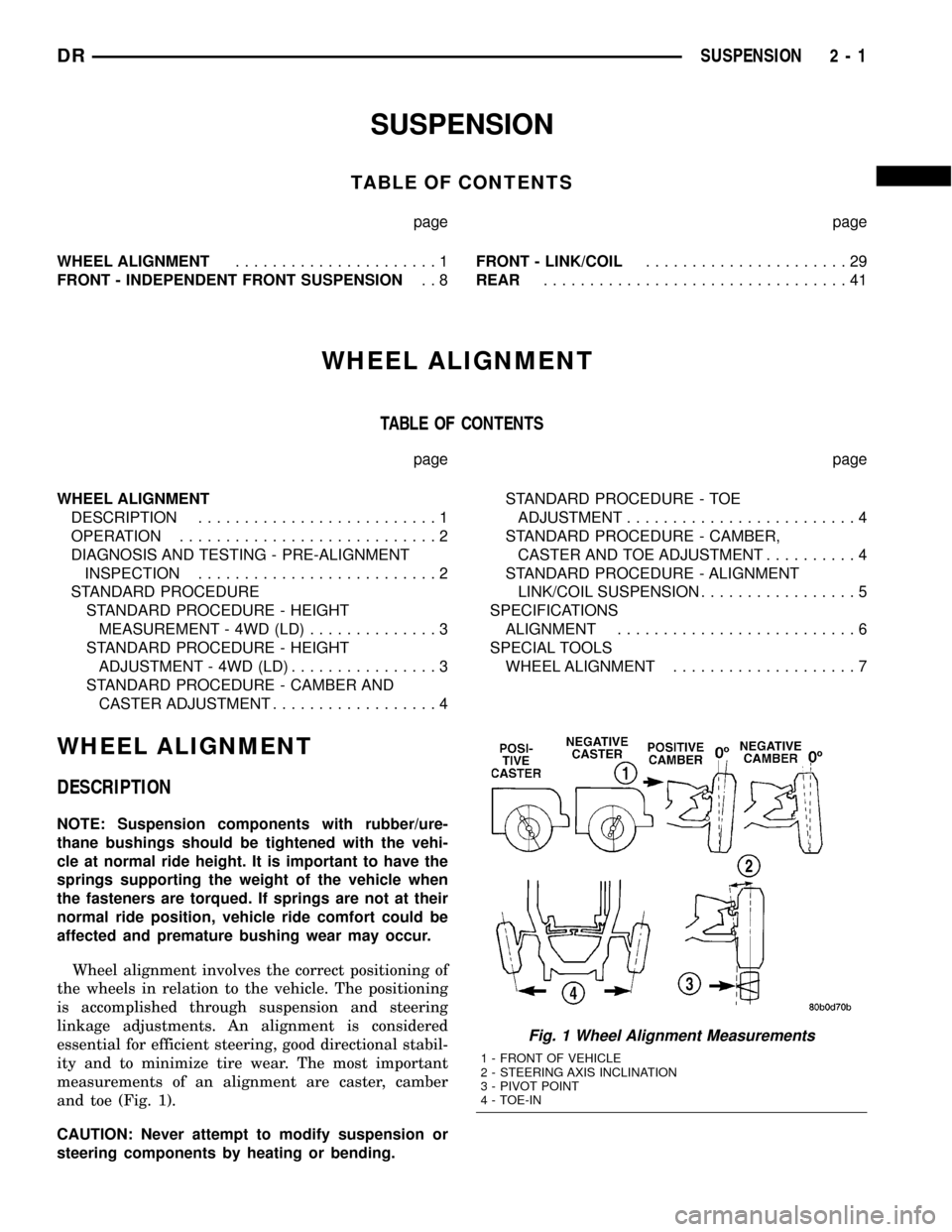
ity and to minimize tire wear. The most important
measurements of an alignment are caster, camber
and toe (Fig. 1).
CAUTION: Never attempt to modify suspension or
steering components by heating or bending.
Fig. 1 Wheel Alignment Measurements
1 - FRONT OF VEHICLE
2 - STEERING AXIS INCLINATION
3 - PIVOT POINT
4 - TOE-IN
DRSUSPENSION 2 - 1
Page 43 of 2627
FRONT - INDEPENDENT FRONT SUSPENSION
TABLE OF CONTENTS
page page
FRONT - INDEPENDENT FRONT SUSPENSION
DESCRIPTION
DESCRIPTION........................9
DESCRIPTION........................10
SPECIFICATIONS
TORQUE CHART......................10
SPECIAL TOOLS
FRONT SUSPENSION..................12
BUSHINGS
REMOVAL
REMOVAL - LOWER CONTROL ARM
BUSHINGS - 4WD (LD).................13
REMOVAL - TORSION BAR
CROSSMEMBER BUSHING..............13
REMOVAL - LOWER CONTROL ARM
BUSHINGS - 2WD (LD).................13
INSTALLATION
INSTALLATION - LOWER CONTROL ARM
BUSHINGS - 4WD (LD).................14
INSTALLATION - TORSION BAR CROSS
MEMBER BUSHING....................15
INSTALLATION - LOWER CONTROL ARM
BUSHINGS - 2WD (LD).................15
HUB / BEARING
REMOVAL
REMOVAL - 4X4......................16
REMOVAL - 4X2......................17
INSTALLATION
INSTALLATION - 4X4...................17
INSTALLATION - 4X2...................18
KNUCKLE
DESCRIPTION.........................18
OPERATION...........................18
REMOVAL.............................18
INSTALLATION.........................19
LOWER BALL JOINT
DIAGNOSIS AND TESTING - LOWER BALL
JOINT..............................19
REMOVAL.............................19
INSTALLATION.........................20
LOWER CONTROL ARM
REMOVAL
REMOVAL - 4X4 (LD)...................21REMOVAL - 4X2......................21
INSTALLATION
INSTALLATION - 4X4 (LD)...............21
INSTALLATION - 4X2...................22
SPRING
REMOVAL.............................22
INSTALLATION.........................23
SHOCK
DIAGNOSIS AND TESTING - SHOCK........24
REMOVAL
REMOVAL - 4X2......................24
REMOVAL - 4X4......................24
INSTALLATION
INSTALLATION - 4X2...................24
INSTALLATION - 4X4...................24
STABILIZER BAR
DESCRIPTION.........................24
OPERATION...........................25
REMOVAL.............................25
INSTALLATION.........................25
STABILIZER LINK
REMOVAL
REMOVAL - 4X4......................25
REMOVAL - 4X2......................25
INSTALLATION
INSTALLATION - 4X4...................26
INSTALLATION - 4X2...................26
TORSION BAR
DESCRIPTION.........................26
OPERATION...........................26
REMOVAL.............................26
INSTALLATION.........................27
UPPER BALL JOINT
DIAGNOSIS AND TESTING - UPPER BALL
JOINT..............................27
UPPER CONTROL ARM
REMOVAL.............................28
INSTALLATION.........................28
2 - 8 FRONT - INDEPENDENT FRONT SUSPENSIONDR
Page 64 of 2627
FRONT - LINK/COIL
TABLE OF CONTENTS
page page
FRONT - LINK/COIL
SPECIFICATIONS
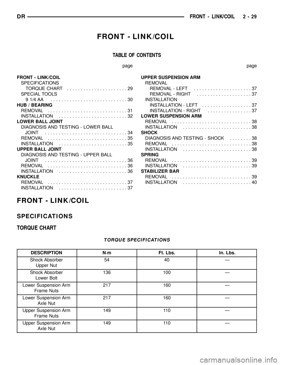
TORQUE CHART......................29
SPECIAL TOOLS
91/4AA ............................30
HUB / BEARING
REMOVAL.............................31
INSTALLATION.........................32
LOWER BALL JOINT
DIAGNOSIS AND TESTING - LOWER BALL
JOINT..............................34
REMOVAL.............................35
INSTALLATION.........................35
UPPER BALL JOINT
DIAGNOSIS AND TESTING - UPPER BALL
JOINT..............................36
REMOVAL.............................36
INSTALLATION.........................36
KNUCKLE
REMOVAL.............................37
INSTALLATION.........................37UPPER SUSPENSION ARM
REMOVAL
REMOVAL - LEFT.....................37
REMOVAL - RIGHT....................37
INSTALLATION
INSTALLATION - LEFT..................37
INSTALLATION - RIGHT................37
LOWER SUSPENSION ARM
REMOVAL.............................38
INSTALLATION.........................38
SHOCK
DIAGNOSIS AND TESTING - SHOCK........38
REMOVAL.............................38
INSTALLATION.........................38
SPRING
REMOVAL.............................39
INSTALLATION.........................39
STABILIZER BAR
REMOVAL.............................39
INSTALLATION.........................40
FRONT - LINK/COIL
SPECIFICATIONS
TORQUE CHART
TORQUE SPECIFICATIONS
DESCRIPTION N´m Ft. Lbs. In. Lbs.
Shock Absorber
Upper Nut54 40 Ð
Shock Absorber
Lower Bolt136 100 Ð
Lower Suspension Arm
Frame Nuts217 160 Ð
Lower Suspension Arm
Axle Nut217 160 Ð
Upper Suspension Arm
Frame Nuts149 110 Ð
Upper Suspension Arm
Axle Nut149 110 Ð
DRFRONT - LINK/COIL 2 - 29
Page 76 of 2627
REAR
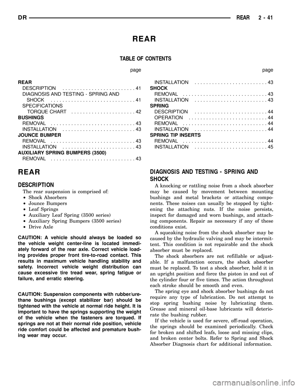
TABLE OF CONTENTS
page page
REAR
DESCRIPTION.........................41
DIAGNOSIS AND TESTING - SPRING AND
SHOCK.............................41
SPECIFICATIONS
TORQUE CHART......................42
BUSHINGS
REMOVAL.............................43
INSTALLATION.........................43
JOUNCE BUMPER
REMOVAL.............................43
INSTALLATION.........................43
AUXILIARY SPRING BUMPERS (3500)
REMOVAL.............................43INSTALLATION.........................43
SHOCK
REMOVAL.............................43
INSTALLATION.........................43
SPRING
DESCRIPTION.........................44
OPERATION...........................44
REMOVAL.............................44
INSTALLATION.........................44
SPRING TIP INSERTS
REMOVAL.............................44
INSTALLATION.........................45
REAR
DESCRIPTION
The rear suspension is comprised of:
²Shock Absorbers
²Jounce Bumpers
²Leaf Springs
²Auxiliary Leaf Spring (3500 series)
²Auxiliary Spring Bumpers (3500 series)
²Drive Axle
CAUTION: A vehicle should always be loaded so
the vehicle weight center-line is located immedi-
ately forward of the rear axle. Correct vehicle load-
ing provides proper front tire-to-road contact. This
results in maximum vehicle handling stability and
safety. Incorrect vehicle weight distribution can
cause excessive tire tread wear, spring fatigue or
failure, and erratic steering.
CAUTION: Suspension components with rubber/ure-
thane bushings (except stabilizer bar) should be
tightened with the vehicle at normal ride height. It is
important to have the springs supporting the weight
of the vehicle when the fasteners are torqued. If
springs are not at their normal ride position, vehicle
ride comfort could be affected and premature bush-
ing wear may occur.
DIAGNOSIS AND TESTING - SPRING AND
SHOCK
A knocking or rattling noise from a shock absorber
may be caused by movement between mounting
bushings and metal brackets or attaching compo-
nents. These noises can usually be stopped by tight-
ening the attaching nuts. If the noise persists,
inspect for damaged and worn bushings, and attach-
ing components. Repair as necessary if any of these
conditions exist.
A squeaking noise from the shock absorber may be
caused by the hydraulic valving and may be intermit-
tent. This condition is not repairable and the shock
absorber must be replaced.
The shock absorbers are not refillable or adjust-
able. If a malfunction occurs, the shock absorber
must be replaced. To test a shock absorber, hold it in
an upright position and force the piston in and out of
the cylinder four or five times. The action throughout
each stroke should be smooth and even.
The spring eye and shock absorber bushings do not
require any type of lubrication. Do not attempt to
stop spring bushing noise by lubricating them.
Grease and mineral oil-base lubricants will deterio-
rate the bushing rubber.
If the vehicle is used for severe, off-road operation,
the springs should be examined periodically. Check
for broken and shifted leafs, loose and missing clips,
and broken center bolts. Refer to Spring and Shock
Absorber Diagnosis chart for additional information.
DRREAR 2 - 41
Page 82 of 2627
DIFFERENTIAL & DRIVELINE
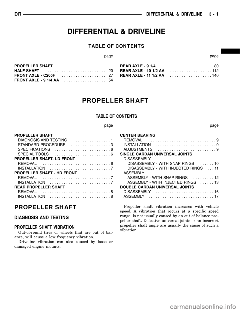
TABLE OF CONTENTS
page page
PROPELLER SHAFT......................1
HALF SHAFT...........................20
FRONT AXLE - C205F....................27
FRONT AXLE - 9 1/4 AA...................54REAR AXLE-91/4.......................80
REAR AXLE - 10 1/2 AA..................112
REAR AXLE - 11 1/2 AA..................140
PROPELLER SHAFT
TABLE OF CONTENTS
page page
PROPELLER SHAFT
DIAGNOSIS AND TESTING................1
STANDARD PROCEDURE.................3
SPECIFICATIONS........................6
SPECIAL TOOLS........................6
PROPELLER SHAFT- LD FRONT
REMOVAL.............................6
INSTALLATION..........................7
PROPELLER SHAFT - HD FRONT
REMOVAL.............................7
INSTALLATION..........................7
REAR PROPELLER SHAFT
REMOVAL.............................8
INSTALLATION..........................8CENTER BEARING
REMOVAL.............................9
INSTALLATION..........................9
ADJUSTMENTS.........................9
SINGLE CARDAN UNIVERSAL JOINTS
DISASSEMBLY
DISASSEMBLY - WITH SNAP RINGS......10
DISASSEMBLY - WITH INJECTED RINGS . . . 11
ASSEMBLY
ASSEMBLY - WITH SNAP RINGS.........12
ASSEMBLY - WITH INJECTED RINGS......13
DOUBLE CARDAN UNIVERSAL JOINTS
DISASSEMBLY.........................16
ASSEMBLY............................17
PROPELLER SHAFT
DIAGNOSIS AND TESTING
PROPELLER SHAFT VIBRATION
Out-of-round tires or wheels that are out of bal-
ance, will cause a low frequency vibration.
Driveline vibration can also caused by loose or
damaged engine mounts.Propeller shaft vibration increases with vehicle
speed. A vibration that occurs at a specific speed
range, is not usually caused by an out of balance pro-
peller shaft. Defective universal joints or an incorrect
propeller shaft angle are usually the cause of such a
vibration.
DRDIFFERENTIAL & DRIVELINE 3 - 1
Page 101 of 2627
HALF SHAFT
TABLE OF CONTENTS
page page
HALF SHAFT
CAUTION.............................20
DIAGNOSIS AND TESTING................20
REMOVAL.............................20
INSTALLATION.........................21
SPECIFICATIONS.......................21
SPECIAL TOOLS.......................21CV JOINT-OUTER
REMOVAL.............................22
INSTALLATION.........................23
CV JOINT-INNER
REMOVAL.............................25
INSTALLATION.........................25
HALF SHAFT
CAUTION
CAUTION:: Never grasp half shaft assembly by the
boots. This may cause the boot to pucker or crease
and reduce the service life of the boot.
Avoid over angulating or stroking the C/V joints
when handling the half shaft.
Half shafts exposed to battery acid, transmission
fluid, brake fluid, differential fluid or gasoline may
cause the boots to deteriorate. Failure to heed cau-
tion may result in damage.
DIAGNOSIS AND TESTING
Check inboard and outboard C/V joint for leaking
grease. This is a sign of boot or boot clamp damage.
NOISE/VIBRATION IN TURNS
A clicking noise or vibration in turns could be
caused by a damaged outer C/V or inner tripod joint
seal boot or seal boot clamps. This will result in the
loss/contamination of the joint grease, resulting in
inadequate lubrication of the joint. Noise could also
be caused by another component of the vehicle com-
ing in contact with the half shafts.
CLUNKING NOISE DURING ACCELERATION
This noise may be a damaged or worn C/V joint. A
torn boot or loose/missing clamp on the inner/outer
joint which has allowed the grease to be lost will
damage the C/V joint.
SHUDDER/VIBRATION DURING ACCELERATION
This could be a worn/damaged inner tripod joint or
a sticking tripod joint. Improper wheel alignment
may also cause a shudder or vibration.
VIBRATION AT HIGHWAY SPEEDS
This problem could be a result of out of balance
front tires or tire/wheel runout. Foreign material
(mud, etc.) packed on the backside of the wheel(s)
will also cause a vibration.
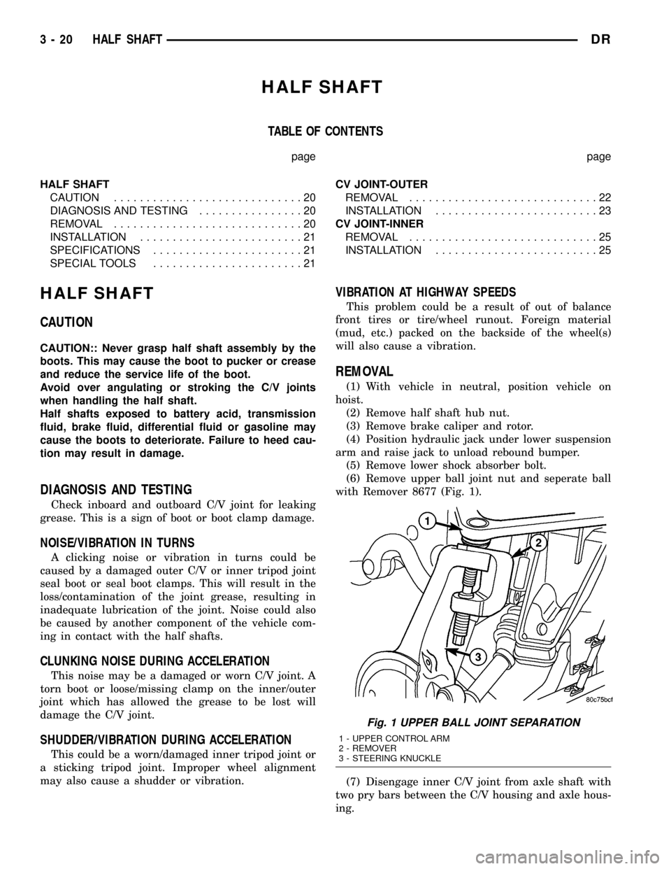
REMOVAL
(1) With vehicle in neutral, position vehicle on
hoist.
(2) Remove half shaft hub nut.
(3) Remove brake caliper and rotor.
(4) Position hydraulic jack under lower suspension
arm and raise jack to unload rebound bumper.
(5) Remove lower shock absorber bolt.
(6) Remove upper ball joint nut and seperate ball
with Remover 8677 (Fig. 1).
(7) Disengage inner C/V joint from axle shaft with
two pry bars between the C/V housing and axle hous-
ing.
Fig. 1 UPPER BALL JOINT SEPARATION
1 - UPPER CONTROL ARM
2 - REMOVER
3 - STEERING KNUCKLE
3 - 20 HALF SHAFTDR
Page 108 of 2627
FRONT AXLE - C205F
TABLE OF CONTENTS
page page
FRONT AXLE - C205F
DIAGNOSIS AND TESTING................27
REMOVAL.............................31
INSTALLATION.........................31
ADJUSTMENTS........................32
SPECIFICATIONS.......................39
SPECIAL TOOLS.......................40
AXLE SHAFTS
REMOVAL.............................43
INSTALLATION.........................43
AXLE SHAFT SEALS
REMOVAL.............................43
INSTALLATION.........................43
AXLE BEARINGS
REMOVAL.............................43INSTALLATION.........................44
PINION SEAL
REMOVAL.............................44
INSTALLATION.........................45
DIFFERENTIAL
REMOVAL.............................46
DISASSEMBLY.........................47
ASSEMBLY............................47
INSTALLATION.........................48
DIFFERENTIAL CASE BEARINGS
REMOVAL.............................48
INSTALLATION.........................48
PINION GEAR/RING GEAR
REMOVAL.............................49
INSTALLATION.........................51
FRONT AXLE - C205F
DIAGNOSIS AND TESTING
GEAR NOISE
Axle gear noise can be caused by insufficient lubri-
cant, incorrect backlash, tooth contact, worn/damaged
gears or the carrier housing not having the proper
offset and squareness.
Gear noise usually happens at a specific speed
range. The noise can also occur during a specific type
of driving condition. These conditions are accelera-
tion, deceleration, coast, or constant load.
When road testing, first warm-up the axle fluid by
driving the vehicle at least 5 miles and then acceler-
ate the vehicle to the speed range where the noise is
the greatest. Shift out-of-gear and coast through the
peak-noise range. If the noise stops or changes
greatly check for:
²Insufficient lubricant.
²Incorrect ring gear backlash.
²Gear damage.
Differential side gears and pinions can be checked
by turning the vehicle. The side gears are loaded dur-
ing turns. They usually do not cause noise during
straight-ahead driving when the gears are unloaded.
A worn pinion mate shaft can also cause a snapping
or a knocking noise.
BEARING NOISE
The axle shaft, differential and pinion bearings can
all produce noise when worn or damaged. Bearing
noise can be either a whining, or a growling sound.
Pinion bearingshave a constant-pitch noise. This
noise changes only with vehicle speed. Pinion bearing
noise will be higher pitched because it rotates at a
faster rate. Drive the vehicle and load the differen-
tial. If bearing noise occurs, the rear pinion bearing
is the source of the noise. If the bearing noise is
heard during a coast, the front pinion bearing is the
source.
Differential bearingsusually produce a low pitch
noise. Differential bearing noise is similar to pinion
bearing noise. The pitch of differential bearing noise
is also constant and varies only with vehicle speed.
Axle shaft bearingsproduce noise and vibration
when worn or damaged. The noise generally changes
when the bearings are loaded. Road test the vehicle.
Turn the vehicle sharply to the left and to the right.
This will load the bearings and change the noise
level. Where axle bearing damage is slight, the noise
is usually not noticeable at speeds above 30 m.p.h.
LOW SPEED KNOCK
Low speed knock is generally caused by:
²Worn U-joints/CV joint.
²Worn side-gear thrust washers.
²Worn pinion shaft bore.
DRFRONT AXLE - C205F 3 - 27
Page 135 of 2627
FRONT AXLE - 9 1/4 AA
TABLE OF CONTENTS
page page
FRONT AXLE - 9 1/4 AA
DIAGNOSIS AND TESTING................54
REMOVAL.............................57
INSTALLATION.........................58
ADJUSTMENTS........................59
SPECIFICATIONS.......................63
SPECIAL TOOLS.......................64
AXLE SHAFTS
REMOVAL.............................67
DISASSEMBLY.........................68
ASSEMBLY............................69
INSTALLATION.........................69
AXLE SHAFT SEALS
REMOVAL.............................69
INSTALLATION.........................70PINION SEAL
REMOVAL.............................70
INSTALLATION.........................71
DIFFERENTIAL
REMOVAL.............................72
DISASSEMBLY.........................72
ASSEMBLY............................73
INSTALLATION.........................74
DIFFERENTIAL CASE BEARINGS
REMOVAL.............................75
INSTALLATION.........................75
PINION GEAR/RING GEAR
REMOVAL.............................75
INSTALLATION.........................77
FRONT AXLE - 9 1/4 AA
DIAGNOSIS AND TESTING
GEAR NOISE
Axle gear noise can be caused by insufficient lubri-
cant, incorrect backlash, tooth contact, worn/damaged
gears or the carrier housing not having the proper
offset and squareness.
Gear noise usually happens at a specific speed
range. The noise can also occur during a specific type
of driving condition. These conditions are accelera-
tion, deceleration, coast, or constant load.
When road testing, first warm-up the axle fluid by
driving the vehicle at least 5 miles and then acceler-
ate the vehicle to the speed range where the noise is
the greatest. Shift out-of-gear and coast through the
peak-noise range. If the noise stops or changes
greatly check for:
²Insufficient lubricant.
²Incorrect ring gear backlash.
²Gear damage.
Differential side gears and pinions can be checked
by turning the vehicle. The side gears are loaded dur-
ing turns. They usually do not cause noise during
straight-ahead driving when the gears are unloaded.
A worn pinion mate shaft can also cause a snapping
or a knocking noise.
BEARING NOISE
The axle shaft, differential and pinion bearings can
all produce noise when worn or damaged. Bearing
noise can be either a whining, or a growling sound.
Pinion bearingshave a constant-pitch noise. This
noise changes only with vehicle speed. Pinion bearing
noise will be higher pitched because it rotates at a
faster rate. Drive the vehicle and load the differen-
tial. If bearing noise occurs, the rear pinion bearing
is the source of the noise. If the bearing noise is
heard during a coast, the front pinion bearing is the
source.
Differential bearingsusually produce a low pitch
noise. Differential bearing noise is similar to pinion
bearing noise. The pitch of differential bearing noise
is also constant and varies only with vehicle speed.
Axle shaft bearingsproduce noise and vibration
when worn or damaged. The noise generally changes
when the bearings are loaded. Road test the vehicle.
Turn the vehicle sharply to the left and to the right.
This will load the bearings and change the noise
level. Where axle bearing damage is slight, the noise
is usually not noticeable at speeds above 30 m.p.h.
LOW SPEED KNOCK
Low speed knock is generally caused by:
²Worn U-joint(s).
²Worn side-gear thrust washers.
²Worn pinion shaft bore.
3 - 54 FRONT AXLE - 9 1/4 AADR