steering wheel DODGE RAM 1500 GAS 2004 3.G User Guide
[x] Cancel search | Manufacturer: DODGE, Model Year: 2004, Model line: RAM 1500 GAS, Model: DODGE RAM 1500 GAS 2004 3.GPages: 429, PDF Size: 7.52 MB
Page 108 of 429

DRIVER ADJUSTABLE PEDALS Ð IF EQUIPPED
The power adjustable accelerator and brake pedals allow
the driver to establish a comfortable position relative to
the steering wheel and pedals.
Adjustment
1. Position the driver seat so that you are at least 10
inches (254 mm) away from the airbag located in the
center of the steering wheel.
2. Fasten and adjust the seatbelts.
3. Move the adjustable pedal switch, located to the left of
the steering column near the parking brake release, in the
direction you desire to move the pedals.
4. The pedalscannotbe adjusted when the vehicle is in
R (Reverse) or when the Speed Control is SET.
108 UNDERSTANDING THE FEATURES OF YOUR VEHICLE
Page 109 of 429
CAUTION!
Do not place any article under the adjustable pedals
or impede its ability to move as it may cause damage
to the pedal controls. Pedal travel may become
limited if movement is stopped by an obstruction in
the adjustable pedal's path.
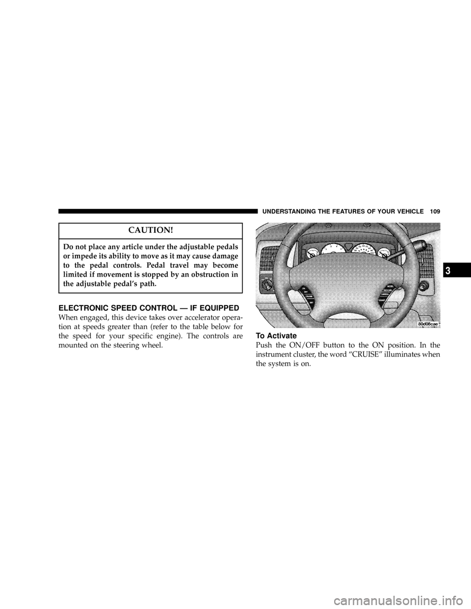
ELECTRONIC SPEED CONTROL Ð IF EQUIPPED
When engaged, this device takes over accelerator opera-
tion at speeds greater than (refer to the table below for
the speed for your specific engine). The controls are
mounted on the steering wheel.
To Activate
Push the ON/OFF button to the ON position. In the
instrument cluster, the word ªCRUISEº illuminates when
the system is on.
UNDERSTANDING THE FEATURES OF YOUR VEHICLE 109
3
Page 181 of 429

By pressing the SEEK button when the PTY icon is
displayed, the radio will be tuned to the next frequency
station with the same selected PTY name. The PTY
function only operates when in the FM mode.
The radio display will flash ªSEEKº and the selected PTY
program type when searching for the next PTY station. If
no station is found with the selected PTY program type,
the radio will return to the last station.
If a preset button is activated while in the PTY (Program
Type) mode, the PTY mode will be exited and the radio
will tune to the preset station.
By pressing the SCAN button when the PTY icon is
displayed, the radio will stop at every PTY station on the
band and list each corresponding program type in the
radio display.
Time
Press the TIME button to change the display from
elapsed CD playing time to time of day.
REMOTE SOUND SYSTEM CONTROLS Ð IF
EQUIPPED
The remote sound system controls are located on the rear
surface of the steering wheel. Reach behind the wheel to
access the switches.
The right hand control is a rocker type switch with a
button in the center. Pressing the top of the switch will
UNDERSTANDING YOUR INSTRUMENT PANEL 181
4
Page 200 of 429

NManually Shifted Transfer Case Operating
Information/Precautions................217
NShifting Procedure - Manually Shifted Transfer
Case..............................219
NTransfer Case Reminder Light............220
NElectronically Shifted Transfer Case Operating
Information/Precautions................221
NShifting Procedure - Electronically Shifted
Transfer Case........................225
mLimited-Slip Differential Ð If Equipped.......228
mParking Brake.........................229
mBrake System..........................230
N3500 Dual Rear Wheel Models Only........231
NBrake Noise.........................231NRear Wheel Anti-Lock Brake
System Ð RWAL.....................231
NFour-Wheel Anti-Lock Brake
System Ð If Equipped..................232
mPower Steering........................234
mTire Safety Information...................234
NTire Markings........................234
NTire Identification Number (TIN)..........238
NTire Loading And Tire Pressure...........239
mTiresÐGeneral Information................243
NTire Pressure.........................243
NTire Inflation Pressures.................244
NRadial-Ply Tires......................247
NCompact Spare Tire Ð If Equipped.........247
200 STARTING AND OPERATING
Page 204 of 429

IGNITION/STARTER SWITCH
LOCK
Locks the automatic transmission shift control into the
PARK position. It also engages the steering wheel lock (if
equipped) when the steering wheel is turned.NOTE: This vehicle is equipped with a transmission
shift interlocking system. The brake pedal must be
depressed to shift out of Park (P).
OFF
Unlocks the steering wheel (if equipped with locking
wheel) and the automatic transmission shift control with
engine off.
ON
This is the normal running position.
START
Starts the engine. When the engine starts, release the key.
The ignition key will return to the ON position for
normal driving.
204 STARTING AND OPERATING
Page 231 of 429

3500 Dual Rear Wheel Models Only
The brake system power assist is provided by a hydro-
boost unit which shares fluid with the power steering
system. You may experience some clicking or hissing
noises from the hydro-boost system during hard braking
conditions.
NOTE:Under cold temperatures, pedal effort will be
higher than normal until the power steering oil reaches
operating temperature.
Brake Noise
During normal operation of the brake system certain
noises may be present from time to time. Occasional
9groan9or9squeal9noises may occur during normal
operation of the brake system which may not be indica-
tive of a problem. These noises may be heard at any time
the brakes are applied but may be more noticeable during
the first few brake applications in the morning. Moisture,
hot or cold temperature, dust, and or other debris mayalso contribute to the noise condition. Repeated or con-
tinuous noises during braking may be an indication that
the brake linings are worn and in need of replacement.
Rear Wheel Anti-Lock Brake System Ð RWAL
The Anti-lock Brake System provides increased vehicle
stability and brake performance under most braking
conditions. The system automatically controls the opera-
tion of the rear brakes to prevent rear wheel lockup.
The system remains operational in the four-wheel drive
mode. The level of performance is reduced when the
front brakes are locked up. This may cause the rear
brakes to lockup through the drivetrain, which may
reduce the effectiveness of the Anti-lock Brake System.
During severe braking conditions, particularly with
changing road surfaces, such as ice to concrete, a slight
drop or minor pulsation may be felt in the brake pedal.
STARTING AND OPERATING 231
5
Page 250 of 429
WARNING!
²Do not use a tire, wheel size or rating other than
that specified for your vehicle. Some combina-
tions of unapproved tires and wheels may change
suspension dimensions and performance charac-
teristics, resulting in changes to steering, han-
dling, and braking of your vehicle. This can cause
unpredictable handling and stress to steering and
suspension components. You could lose control
and have an accident resulting in serious injury or
death. Use only the tire and wheel sizes with load
ratings approved for your vehicle.
²Never use a tire with a smaller load index or
capacity, other than what was originally equipped
on your vehicle. Using a tire with a smaller load
index could result in tire overloading and failure.
You could lose control and have an accident.
²Failure to equip your vehicle with tires having
adequate speed capability can result in sudden
tire failure and loss of vehicle control.
CAUTION!
Replacing original tires with tires of a different size
may result in false speedometer and odometer read-
ings.
Alignment And Balance
Poor suspension alignment may result in:
²Fast tire wear.
²Uneven tire wear, such as feathering and one-sided
wear.
²Vehicle pull to right or left.
Tires may also cause the vehicle to pull to the left or right.
Alignment will not correct this condition. See your dealer
for proper diagnosis.
250 STARTING AND OPERATING
Page 320 of 429

NMaintenance Free Battery................337
NAir Conditioner Maintenance.............338
NPower Steering Ð Fluid Check............339
NFront Suspension Ball Joints..............340
NSteering Linkage Ð Inspection............341
NHalf-Shaft Constant Velocity Joints.........341
NBody Lubrication.....................341
NWindshield Wiper Blades................342
NWindshield Washers...................342
NExhaust System......................343
NCooling System.......................344
NHoses And Vacuum/Vapor Harnesses.......347
NBrake System........................348NClutch Hydraulic System................349
NClutch Linkage.......................350
NPropeller Shaft Universal Joints...........350
NRear Axle And 4X4 Front Driving Axle
Fluid Level..........................350
NTransfer Case........................351
NManual Transmission..................351
NAutomatic Transmission................352
NFront Wheel Bearings..................355
NSelection Of Lubricating Grease...........356
NNoise Control System Required Maintenance &
Warranty For 3500 2-Wheel Drive And 4-Wheel
Drive Models Over 10,000 Lbs. (4 535 Kg) Gross
Vehicle Weight Rating...................356
320 MAINTAINING YOUR VEHICLE
Page 341 of 429

Steering Linkage Ð Inspection
Whenever the vehicle is hoisted, all steering linkage
joints should be inspected for evidence of damage. If
seals are damaged, parts should be replaced to prevent
leakage or contamination of the grease. Lubricate the
steering linkage regularly according to the ªMaintenance
Scheduleº in this manual.
Half-shaft Constant Velocity Joints
All four- wheel- drive 1500 models are equipped with
four constant velocity joints. Periodic lubrication of these
joints is not required. However, the joint boots should be
inspected for external leakage or damage periodically. If
external leakage or damage is evident, the joint boot and
grease should be replaced immediately. Continued op-
eration could result in failure of the joint due to water
and dirt contamination of the grease. This would require
complete replacement of the joint assembly. Refer to the
Service Manual for the detailed replacement procedure.
Body Lubrication
Locks and all body pivot points, including such items as
seat tracks, doors, tailgate and hood hinges, should be
lubricated periodically to assure quiet, easy operation
and to protect against rust and wear. Prior to the appli-
cation of any lubricant, the parts concerned should be
wiped clean to remove dust and grit; after lubricating
excess oil and grease should be removed. Particular
attention should also be given to hood latching compo-
nents to insure proper function. When performing other
underhood services, the hood latch, release mechanism
and safety catch should be cleaned and lubricated.
The external lock cylinders should be lubricated twice a
year, preferably in the fall and spring. Apply a small
amount of a high quality lubricant such as MopartLock
Cylinder Lubricant directly into the lock cylinder.
MAINTAINING YOUR VEHICLE 341
7
Page 418 of 429

Exhaust System.......................69,343
Exterior Lighting........................ 101
Filters
Air Cleaner........................334,357
Engine Fuel.......................... 334
Engine Oil........................333,381
Engine Oil Disposal.................... 332
Flashers
Turn Signal.......................... 103
Flat Tire Stowage.....................301,311
Flexible Fuel Vehicles
Cruising Range........................ 265
Engine Oil........................... 264
Fuel Requirements..................262,263
Maintenance.......................... 265
Replacement Parts..................... 265
Starting............................. 265
Flooded Engine Starting................... 206Fluid, Brake........................... 382
Fluid Capacities......................... 379
Fluid Level Checks
Automatic Transmission................. 352
Power Steering........................ 339
Fog Lights..........................102,378
Fold Flat Load Floor..................... 130
Four Wheel Drive....................... 216
Four-Way Hazard Flasher.................. 294
Freeing A Stuck Vehicle................... 316
Front Axle............................. 350
Front Wheel Bearings..................... 355
Fuel................................. 256
Adding............................. 259
Filter............................... 334
Gauge.............................. 150
Octane Rating......................256,381
Requirements......................256,379
Tank Capacity........................ 379
418 INDEX