sensor DODGE RAM 1999 Service Repair Manual
[x] Cancel search | Manufacturer: DODGE, Model Year: 1999, Model line: RAM, Model: DODGE RAM 1999Pages: 1691, PDF Size: 40.34 MB
Page 960 of 1691
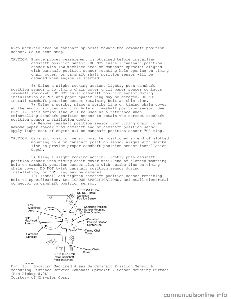
high machined area on camshaft sprocket toward the camshaft position
sensor. Go to next step.
CAUTION: Ensure proper measurement is obtained before installing
camshaft position sensor. DO NOT install camshaft position
sensor with low machined area on camshaft sprocket aligned
with camshaft position sensor mounting hole opening on timing
chain cover, or camshaft shaft position sensor will be
damaged when engine is started.
6) Using a slight rocking action, lightly push camshaft
position sensor into timing chain cover until paper spacer contacts
camshaft sprocket. DO NOT twist camshaft position sensor during
installation or "O" and paper spacer ring may be damaged. DO NOT
install camshaft position sensor retaining bolt at this time.
7) Using a scribe, place a scribe line on timing chain cover
at the end of slotted mounting hole on camshaft position sensor. See
Fig. 17 . This scribe line will be used as a reference when
reinstalling camshaft position sensor to obtain the correct camshaft
position sensor installation depth.
8) Remove camshaft position sensor from timing chain cover.
Remove paper spacer from camshaft end of camshaft position sensor.
Apply light coat of engine oil on camshaft position sensor "O" ring.
CAUTION: Camshaft position sensor must be positioned so end of slotted
mounting hole on camshaft position sensor aligns with scribe
line to provide proper camshaft position sensor installation
depth.
9) Using a slight rocking action, lightly push camshaft
position sensor into timing chain cover until end of slotted mounting
hole on camshaft position sensor aligns with scribe line on timing
chain cover. DO NOT twist camshaft position sensor during
installation, or "O" ring may be damaged.
10) Install and tighten camshaft position sensor retaining
bolt to specification. See TORQUE SPECIFICATIONS. Reinstall electrical
connector on camshaft position sensor.
Fig. 15: Locating Machined Areas On Camshaft Position Sensor &
Measuring Distance Between Camshaft Sprocket & Sensor Mounting Surface
(Ram Pickup 8.0L)
Courtesy of Chrysler Corp.
Page 961 of 1691
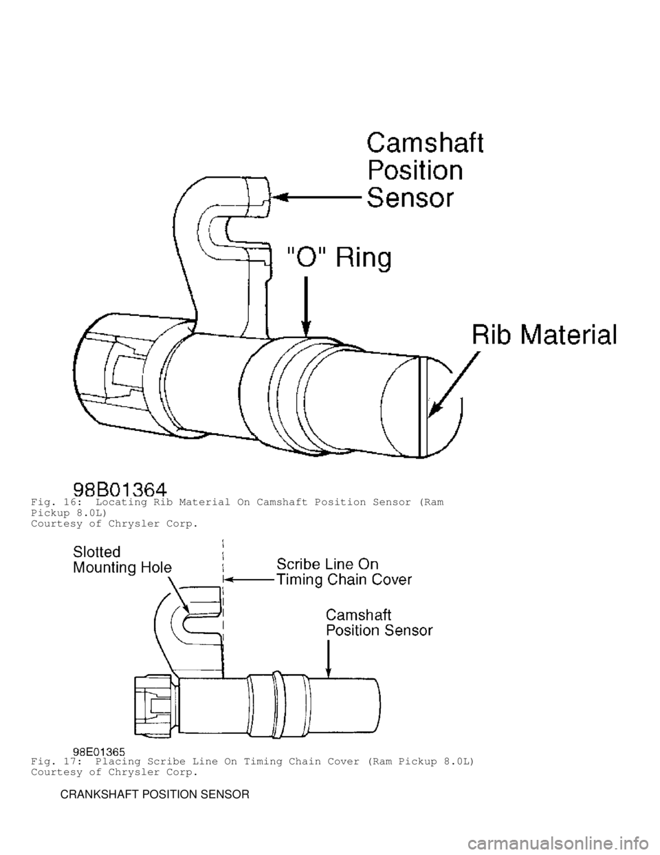
Fig. 16: Locating Rib Material On Camshaft Position Sensor (Ram
Pickup 8.0L)
Courtesy of Chrysler Corp.
Fig. 17: Placing Scribe Line On Timing Chain Cover (Ram Pickup 8.0L)
Courtesy of Chrysler Corp.
CRANKSHAFT POSITION SENSOR
Page 962 of 1691

Removal & Installation (Dakota 2.5L)
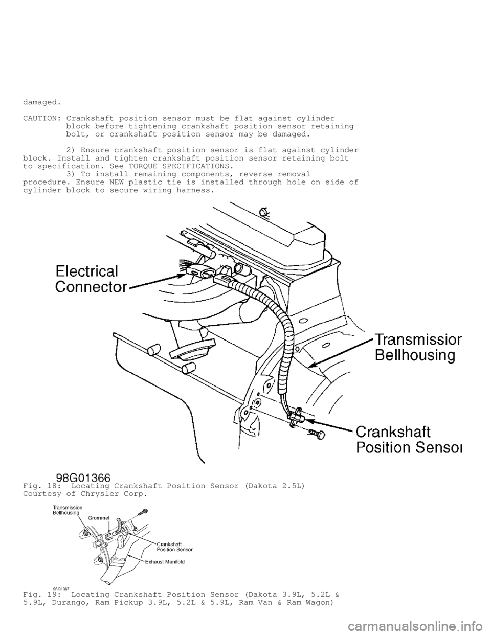
1) Crankshaft position sensor is located on driver's side of
engine at transmission bellhousing. See Fig. 18. Remove air inlet duct
between throttle body and air cleaner assembly.
2) Disconnect electrical connector for crankshaft position
sensor. Remove crankshaft position sensor retaining bolts and
crankshaft position sensor.
CAUTION: Retaining bolts for crankshaft position sensor are specially
machined bolts to provide correct clearance between
crankshaft position sensor and the flywheel. DO NOT use any
other type retaining bolts.
3) To install, reverse removal procedure. Tighten crankshaft
position sensor retaining bolts to specification. See TORQUE
SPECIFICATIONS.
Removal & Installation (Dakota 3.9L, 5.2L & 5.9L, & Durango)
1) Crankshaft position sensor is located on passenger side of
engine at transmission bellhousing, just behind the cylinder head. See
Fig. 19 . Passenger's side front fender wheelwell must be removed for
access to crankshaft position sensor.
2) Raise and support vehicle. Remove passenger side front
wheel. Remove wheel opening molding. Remove plastic rivets attaching
wheelwell to front fender. Remove wheelwell.
3) Disconnect electrical connector for crankshaft position
sensor. Remove crankshaft position sensor retaining bolts and
crankshaft position sensor.
4) To install, reverse removal procedure. Tighten crankshaft
position sensor retaining bolts and wheel lug nuts to specification.
See TORQUE SPECIFICATIONS.
Removal & Installation (Ram Pickup 3.9L, 5.2L & 5.9L, Ram Van
& Ram Wagon)
1) Crankshaft position sensor is located on passenger side of
engine at transmission bellhousing, just behind the cylinder head. See
Fig. 19 .
2) On Ram Van and Ram Wagon, remove engine cover. On Ram
Pickup, remove air inlet duct for access to crankshaft position
sensor.
3) On all models, disconnect electrical connector for
crankshaft position sensor. Remove crankshaft position sensor
retaining bolts and crankshaft position sensor.
4) To install, reverse removal procedure. Tighten crankshaft
position sensor retaining bolts to specification. See TORQUE
SPECIFICATIONS.
Removal (Ram Pickup 8.0L)
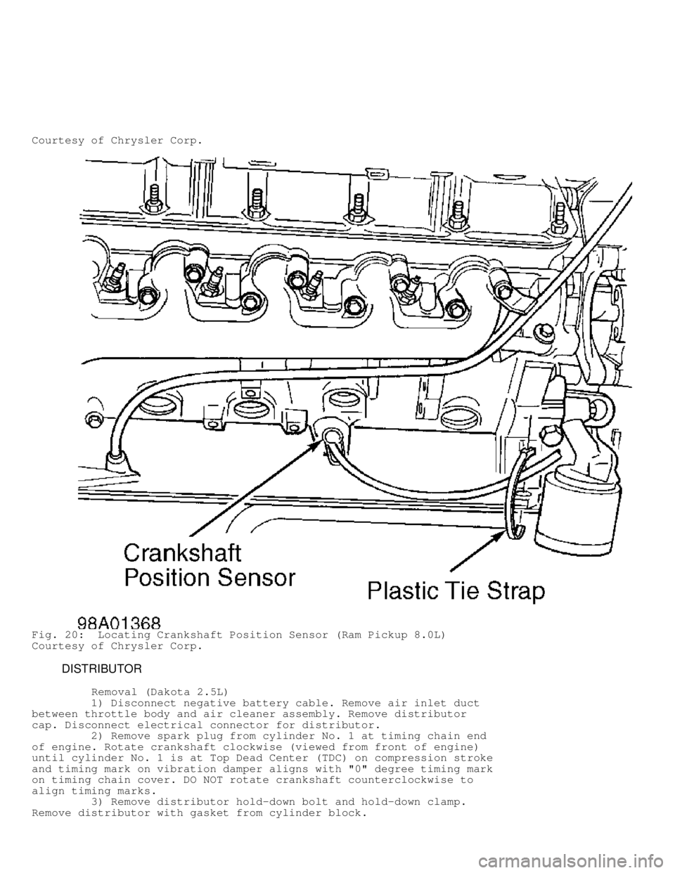
1) Crankshaft position sensor is located on passenger's side
of cylinder block, just above the oil pan. See Fig. 20.
2) Raise and support vehicle. Disconnect electrical connector
for crankshaft position sensor. Remove plastic tie strap securing
wiring harness to side of cylinder block.
3) Remove crankshaft position sensor retaining bolt. Using 2
small screwdrivers, carefully pry crankshaft position sensor with "O"
ring from cylinder block by rocking crankshaft position sensor back
and forth.
Installation
1) Apply light coat of engine oil on crankshaft position
sensor "O" ring. Install crankshaft position sensor in cylinder block
by rocking crankshaft position sensor back and forth. DO NOT twist
crankshaft position sensor during installation, or "O" ring may be
Page 963 of 1691
damaged.
CAUTION: Crankshaft position sensor must be flat against cylinder
block before tightening crankshaft position sensor retaining
bolt, or crankshaft position sensor may be damaged.
2) Ensure crankshaft position sensor is flat against cylinder
block. Install and tighten crankshaft position sensor retaining bolt
to specification. See TORQUE SPECIFICATIONS.
3) To install remaining components, reverse removal
procedure. Ensure NEW plastic tie is installed through hole on side of
cylinder block to secure wiring harness.
Fig. 18: Locating Crankshaft Position Sensor (Dakota 2.5L)
Courtesy of Chrysler Corp.
Fig. 19: Locating Crankshaft Position Sensor (Dakota 3.9L, 5.2L &
5.9L, Durango, Ram Pickup 3.9L, 5.2L & 5.9L, Ram Van & Ram Wagon)
Page 964 of 1691
Courtesy of Chrysler Corp.
Fig. 20: Locating Crankshaft Position Sensor (Ram Pickup 8.0L)
Courtesy of Chrysler Corp.
DISTRIBUTOR
Removal (Dakota 2.5L)
1) Disconnect negative battery cable. Remove air inlet duct
between throttle body and air cleaner assembly. Remove distributor
cap. Disconnect electrical connector for distributor.
2) Remove spark plug from cylinder No. 1 at timing chain end
of engine. Rotate crankshaft clockwise (viewed from front of engine)
until cylinder No. 1 is at Top Dead Center (TDC) on compression stroke\
and timing mark on vibration damper aligns with "0" degree timing mark
on timing chain cover. DO NOT rotate crankshaft counterclockwise to
align timing marks.
3) Remove distributor hold-down bolt and hold-down clamp.
Remove distributor with gasket from cylinder block.
Page 966 of 1691
rotate crankshaft clockwise (viewed from front of engine) until
cylinder No. 1 is at Top Dead Center (TDC) on compression stroke and
timing mark on vibration damper aligns with "0" degree timing mark on
timing chain cover. DO NOT rotate crankshaft counterclockwise to align
timing marks. Go to next step.
3) Check position of slot in oil pump drive gear in cylinder
block. The slot in oil pump drive gear should be at approximately the
10 o'clock position. Rotate oil pump drive gear if necessary.
4) If installing a factory replacement distributor, go to
next step. If installing original or used distributor, remove camshaft
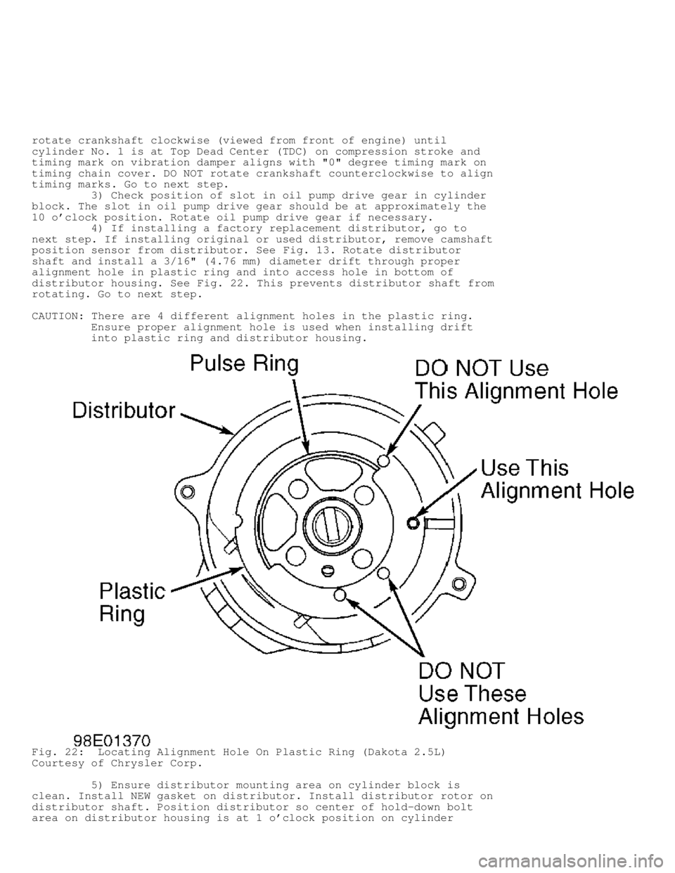
position sensor from distributor. See Fig. 13. Rotate distributor
shaft and install a 3/16" (4.76 mm) diameter drift through proper
alignment hole in plastic ring and into access hole in bottom of
distributor housing. See Fig. 22. This prevents distributor shaft from
rotating. Go to next step.
CAUTION: There are 4 different alignment holes in the plastic ring.
Ensure proper alignment hole is used when installing drift
into plastic ring and distributor housing.
Fig. 22: Locating Alignment Hole On Plastic Ring (Dakota 2.5L)
Courtesy of Chrysler Corp.
5) Ensure distributor mounting area on cylinder block is
clean. Install NEW gasket on distributor. Install distributor rotor on
distributor shaft. Position distributor so center of hold-down bolt
area on distributor housing is at 1 o'clock position on cylinder
Page 967 of 1691
block. Install distributor so distributor shaft engages with slot in
oil pump drive gear. It may be necessary to slightly rotate
distributor during installation.
6) When distributor is fully seated, the distributor rotor
should be at 3 o'clock position and center of hold-down bolt area on
distributor housing should align with distributor hold-down bolt area
on cylinder block.
7) Install hold-down clamp and distributor hold-down bolt.
Tighten distributor hold-down bolt to specification. See TORQUE
SPECIFICATIONS.
8) If installing a factory replacement distributor, remove
plastic alignment pin from distributor housing. If installing original
or used distributor, remove drift from distributor housing and
reinstall camshaft position sensor. On all applications, install
distributor cap and remaining components. Base ignition timing is
nonadjustable, as ignition timing and timing advance are controlled by
the Powertrain Control Module (PCM).
Removal (Dakota 3.9L, 5.2L & 5.9L, Durango, Ram Pickup 3.9L,
5.2L & 5.9L, Ram Van & Ram Wagon)
1) Disconnect negative battery cable. On Ram Van and Ram
Wagon, remove engine cover. On all models, remove air cleaner
assembly. Remove distributor cap. Disconnect electrical connector for
distributor.
2) Rotate crankshaft clockwise (viewed from front of engine)\
until cylinder No. 1 is at Top Dead Center (TDC) on compression stroke\
and timing mark on vibration damper aligns with TDC timing mark on
timing chain cover. Cylinder No. 1 is the front cylinder on driver's
side of engine.
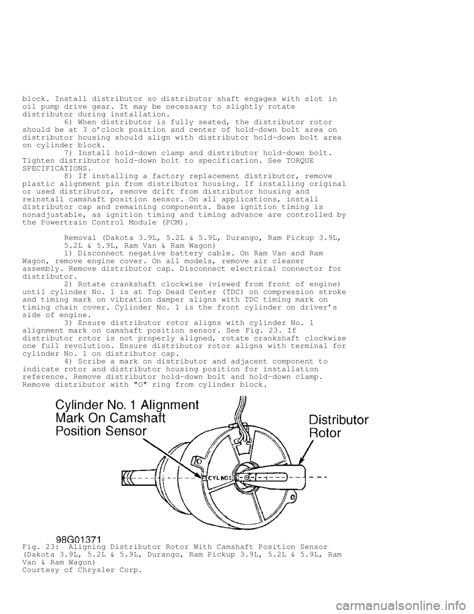
3) Ensure distributor rotor aligns with cylinder No. 1
alignment mark on camshaft position sensor. See Fig. 23. If
distributor rotor is not properly aligned, rotate crankshaft clockwise
one full revolution. Ensure distributor rotor aligns with terminal for
cylinder No. 1 on distributor cap.
4) Scribe a mark on distributor and adjacent component to
indicate rotor and distributor housing position for installation
reference. Remove distributor hold-down bolt and hold-down clamp.
Remove distributor with "O" ring from cylinder block.
Fig. 23: Aligning Distributor Rotor With Camshaft Position Sensor
(Dakota 3.9L, 5.2L & 5.9L, Durango, Ram Pickup 3.9L, 5.2L & 5.9L, Ram
Van & Ram Wagon)
Courtesy of Chrysler Corp.
Page 968 of 1691

Installation
1) If engine has not been rotated after removing distributor,
go to next step. If engine was rotated after removing distributor,
rotate crankshaft clockwise (viewed from front of engine) until
cylinder No. 1 is at Top Dead Center (TDC) on compression stroke and
timing mark on vibration damper aligns with TDC timing mark on timing
chain cover. Go to next step.
2) Ensure distributor mounting area on cylinder block is
clean. Install NEW "O" ring on distributor if necessary. Apply light
coat of engine oil on "O" ring.
3) Position distributor rotor so it aligns with terminal for
cylinder No. 1 on distributor cap. Install distributor. Ensure
distributor engages with slot in oil pump drive gear. Install hold-
down clamp and distributor hold-down bolt. DO NOT tighten distributor
hold-down bolt at this time.
4) Rotate distributor until distributor rotor aligns with
cylinder No. 1 alignment mark on camshaft position sensor. See Fig. 23
. Tighten distributor hold-down bolt to specification. See TORQUE
SPECIFICATIONS. To install remaining components, reverse removal
procedure.
5) Base ignition timing is nonadjustable. Base ignition
timing and timing advance are controlled by the Powertrain Control
Module (PCM). Distributor position is used to determine the fuel
system synchronization. To check for correct distributor position and
fuel system synchronization, see FUEL SYSTEM SYNCHRONIZATION under
FUEL SYSTEM in ON-VEHICLE ADJUSTMENTS article.
IGNITION COIL
Removal & Installation (Dakota 2.5L)
Ignition coil is located on side of engine, near distributor.
Service procedure is primarily an unbolt and bolt-on procedure.
Tighten ignition coil retaining bolts or nuts to specification. See
TORQUE SPECIFICATIONS.
Removal & Installation (Dakota 3.9L, 5.2L & 5.9L, Durango &
Ram Van/Wagon)
1) Ignition coil is located on front of passenger's side
cylinder head. Disconnect spark plug wires and electrical connector
from ignition coil.
CAUTION: Ignition coil-to-cylinder head mounting bracket bolts hold
the idler pulley for the accessory drive belt, as these bolts
are under tension. If necessary to remove these bolts,
accessory drive belt must be removed first.
2) Remove ignition coil retaining bolts or nuts with ignition
coil from the ignition coil mounting bracket. DO NOT remove ignition
coil-to-cylinder head mounting bracket bolts, as these bolts are under
tension.
3) To install, reverse removal procedure. Tighten ignition
coil retaining bolts or nuts to specification. See TORQUE
SPECIFICATIONS.
Removal & Installation (Ram Pickup 3.9L, 5.2L & 5.9L)
1) On 3.9L, 5.2L and 5.9L with light-duty emissions, ignition
coil is located on front of passenger's side cylinder head. On 5.9L
with heavy-duty emissions, ignition coil is located on top of air
injection pump. On all models, disconnect spark plug wires and
electrical connector from ignition coil.
CAUTION: On 3.9L, 5.2L and 5.9L with light-duty emissions, ignition
coil-to-cylinder head mounting bracket bolts hold the idler
Page 976 of 1691
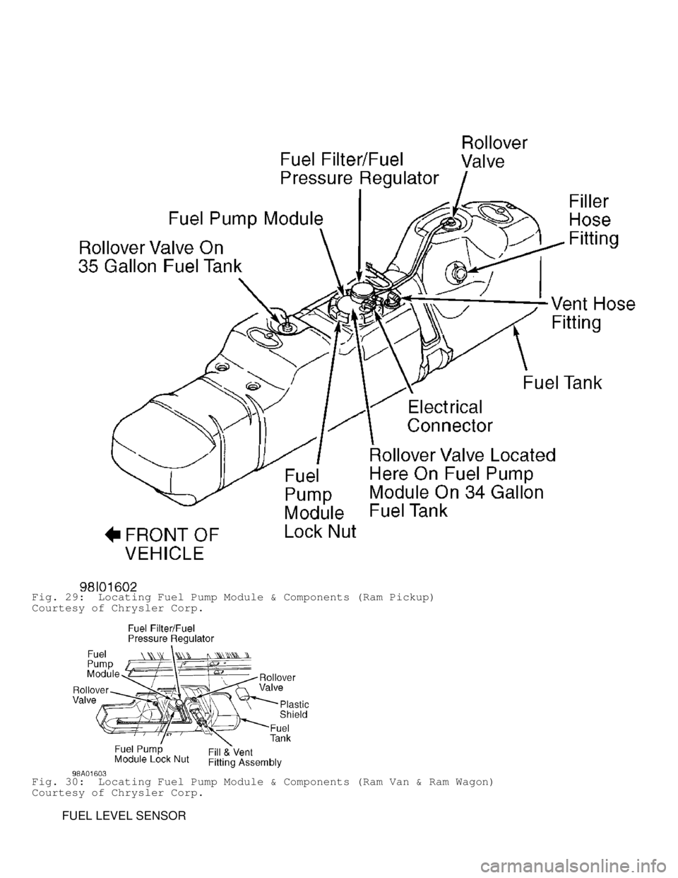
Fig. 29: Locating Fuel Pump Module & Components (Ram Pickup)
Courtesy of Chrysler Corp.
Fig. 30: Locating Fuel Pump Module & Components (Ram Van & Ram Wagon)\
Courtesy of Chrysler Corp.
FUEL LEVEL SENSOR
Page 977 of 1691
NOTE: Fuel level sensor may also be referred to as fuel gauge
sending unit.
Removal
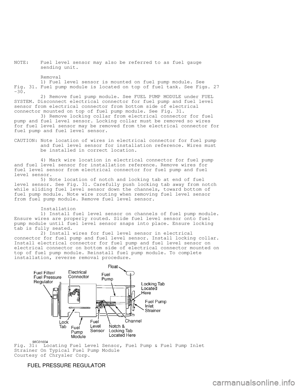
1) Fuel level sensor is mounted on fuel pump module. See
Fig. 31 . Fuel pump module is located on top of fuel tank. See Figs. 27
-30.
2) Remove fuel pump module. See FUEL PUMP MODULE under FUEL
SYSTEM. Disconnect electrical connector for fuel pump and fuel level
sensor from electrical connector from bottom side of electrical
connector mounted on top of fuel pump module. See Fig. 31.
3) Remove locking collar from electrical connector for fuel
pump and fuel level sensor. Locking collar must be removed so wires
for fuel level sensor may be removed from the electrical connector for
fuel pump and fuel level sensor.
CAUTION: Note location of wires in electrical connector for fuel pump
and fuel level sensor for installation reference. Wires must
be installed in correct location.
4) Mark wire location in electrical connector for fuel pump
and fuel level sensor for installation reference. Remove wires for
fuel level sensor from electrical connector for fuel pump and fuel
level sensor.
5) Note location of notch and locking tab at end of fuel
level sensor. See Fig. 31. Carefully push locking tab away from notch
while sliding fuel level sensor down the channels, toward bottom of
fuel pump module. Note wire routing when removing fuel level sensor
from fuel pump module. Remove fuel level sensor.
Installation
1) Install fuel level sensor on channels of fuel pump module.
Ensure wires are properly routed. Slide fuel level sensor onto fuel
pump module until fuel level sensor snaps into place. Ensure locking
tab is fully seated.
2) Install wires for fuel level sensor in electrical
connector for fuel pump and fuel level sensor. Install locking collar.
Install electrical connector for fuel pump and fuel level sensor on
electrical connector on bottom side of electrical connector mounted on
top of fuel pump module. Reinstall fuel pump module. To complete
installation, reverse removal procedure.
Fig. 31: Locating Fuel Level Sensor, Fuel Pump & Fuel Pump Inlet
Strainer On Typical Fuel Pump Module
Courtesy of Chrysler Corp.
FUEL PRESSURE REGULATOR