escape DODGE RAM 1999 Service Repair Manual
[x] Cancel search | Manufacturer: DODGE, Model Year: 1999, Model line: RAM, Model: DODGE RAM 1999Pages: 1691, PDF Size: 40.34 MB
Page 174 of 1691
protective cover is fitted to front of air bag module bearing the SRS
air bag logo. Air bag module contains air bag cushion, inflator and
supporting components. Air bag module is a sealed unit and is not
serviceable. The module inflator assembly produces nitrogen gas to
fill air bag cushion when a small amount of current from ACM is
applied to the ignitor assembly. Gas pressure builds and discharges
from inflator through a diffuser and screen assembly, forcing steering
wheel cover to burst along its seams until air bag is fully inflated.
Once air bag cushion is fully inflated, gas escapes from bag through
vents, away from driver.
Passenger-Side
Air bag module is mounted to instrument panel mounting
bracket. Module is covered by a protective door bearing the SRS air
bag logo. When supplied an electrical signal, inflator will discharge
argon gas directly into air bag. When air bag inflates, protective
door will pivot aside allowing air bag to deploy.
AIR BAG CONTROL MODULE (ACM)
ACM is located under instrument panel, on transmission
tunnel. Impact sensor, energy reserve capacitor and On-Board
Diagnostics (OBD) are an integral part of ACM. ACM monitors critical
input and output circuits within air bag system, ensuring they are
operating correctly. Some circuits are tested continuously; others are
checked only under certain conditions. ACM provides information about
air bag system through AIR BAG warning light and Data Link Connector
(DLC). When diagnostic trouble code (fault message) is stored, AIR B\
AG
warning light will be activated for 12 seconds or more.
DATA LINK CONNECTOR (DLC)
DLC is located under left side of instrument panel, left of
steering column. DLC is used to access SRS on-board diagnostics.
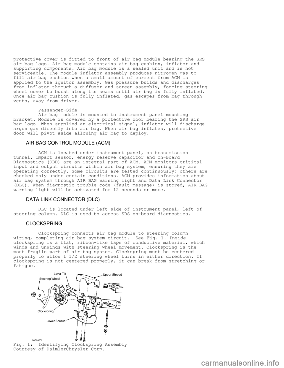
CLOCKSPRING
Clockspring connects air bag module to steering column
wiring, completing air bag system circuit. See Fig. 1. Inside
clockspring is a flat, ribbon-like tape of conductive material, which
winds and unwinds with steering wheel movement. Clockspring is the
most fragile part of air bag system. Clockspring must be centered
properly to allow 1 1/2 steering wheel turns in either direction. If
clockspring is not centered properly, it can break from stretching or
fatigue.
Fig. 1: Identifying Clockspring Assembly
Courtesy of DaimlerChrysler Corp.
Page 177 of 1691

WARNING: Vehicle interior will contain sodium hydroxide powder, a
by-product of air bag deployment. Since this powder can
irritate skin, eyes, nose, or throat, be sure to wear
safety glasses, rubber gloves and long-sleeved shirt
during clean-up.
1) Begin clean-up by putting tape over air bag exhaust vent,
so no additional powder will escape into vehicle interior. Remove air
bag modules. Use a vacuum cleaner to remove any residual powder from
vehicle interior. To avoid kneeling or sitting on a non-cleaned area,
clean from outside vehicle and work your way inside.
2) Remove any residual powder from A/C-heater outlets. Turn
blower motor to low for a few minutes and exit vehicle. Turn blower
off. Vacuum any additional powder expelled from plenum. Vacuum
interior a second time to recover all powder.
DEPLOYED AIR BAG
Dispose of deployed air bag module as any other part. No
special disposal procedure is required.
UNDEPLOYED AIR BAG
NOTE: Information on passenger-side air bag deployment is not
available from manufacturer.
Procedure 1: In-Vehicle Deployment (Driver-Side Air Bag)
1) Use this procedure if scrapping a vehicle with an
undeployed air bag. This procedure assumes that air bag wiring is
intact.
2) Disconnect and shield negative battery cable. Disconnect
2-pin clockspring at base of steering column. Cut 2-pin clockspring
connector of at clockspring side of harness.
3) Strip 1" (25 mm) of insulation from wire ends. Make a
harness consisting of 2 wires 20 feet or longer. Connect 20-foot wires
to clockspring harness. Ensure there are no loose parts in passenger
compartment and no one is within 20 feet of vehicle.
4) Staying at least 20 feet away from vehicle, connect other
2 ends of 20 foot wires to terminals of a 12-volt battery. When
deployment is achieved, loud bang will be heard and air bag will
inflate. After air bag module deploys, let module cool and dust settle
before approaching. If air bag fails to deploy, go to PROCEDURE 2.
Procedure 2: Remote Deployment (Driver-Side Air Bag)
1) Use this procedure if scrapping a vehicle with a live air
bag, but a problem in electrical system prevent deployment with air
bag still installed in vehicle. Also use this procedure if PROCEDURE 1
was unsuccessful.
WARNING: Perform remote deployment outdoors. Never attempt to deploy
air bag module inside a building, within 20 feet of
personnel, or with air bag trim cover face down.
2) Before proceeding, see SERVICE PRECAUTIONS. Disable air
bag system. See DISABLING & ACTIVATING AIR BAG SYSTEM . Remove air bag
module. See DRIVER-SIDE AIR BAG MODULE under REMOVAL & INSTALLATION.
3) cut pigtail wiring harness between clockspring and air bag
as close to clockspring housing as possible. Reconnect other end of
pigtail harness back into air bag module.
4) Strip 1" (25 mm) of insulation from cut ends of harness.
Place air bag module face (trim cover) up. Connect two 20-foot wires
to end of harness wires. Move 20 feet away. Connect other end of 200-