lug pattern DODGE RAM 2001 Service User Guide
[x] Cancel search | Manufacturer: DODGE, Model Year: 2001, Model line: RAM, Model: DODGE RAM 2001Pages: 2889, PDF Size: 68.07 MB
Page 1583 of 2889
(3) Once injector has been found to be malfunc-
tioning, remove it from engine and test it. Refer to
Fuel Injector Removal/Installation.
WARNING: FUEL INJECTOR TESTERS CAN
DEVELOP EXTREMELY HIGH PRESSURES. FUEL
UNDER THIS AMOUNT OF PRESSURE CAN PENE-
TRATE SKIN AND CAUSE PERSONAL INJURY.
WEAR SAFETY GOGGLES AND ADEQUATE PRO-TECTIVE CLOTHING. AVOID CONTACT WITH FUEL
SPRAY WHEN OPERATING INJECTOR TESTOR.
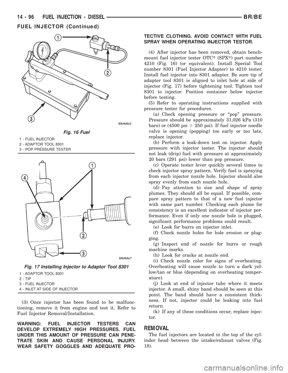
(4) After injector has been removed, obtain bench-
mount fuel injector tester OTCt(SPXt) part number
4210 (Fig. 16) (or equivalent). Install Special Tool
number 8301 (Fuel Injector Adapter) to 4210 tester.
Install fuel injector into 8301 adapter. Be sure tip of
adapter tool 8301 is aligned to inlet hole at side of
injector (Fig. 17) before tightening tool. Tighten tool
8301 to injector. Position container below injector
before testing.
(5) Refer to operating instructions supplied with
pressure tester for procedures.
(a) Check opening pressure or ªpopº pressure.
Pressure should be approximately 31,026 kPa (310
bars) or (4500 psi6250 psi). If fuel injector needle
valve is opening (popping) too early or too late,
replace injector.
(b) Perform a leak-down test on injector. Apply
pressure with injector tester. The injector should
not leak (drip) fuel with pressure at approximately
20 bars (291 psi) lower than pop pressure.
(c) Operate tester lever quickly several times to
check injector spray pattern. Verify fuel is spraying
from each injector nozzle hole. Injector should also
spray evenly from each nozzle hole.
(d) Pay attention to size and shape of spray
plumes. They should all be equal. If possible, com-
pare spray pattern to that of a new fuel injector
with same part number. Checking each plume for
consistency is an excellent indicator of injector per-
formance. Even if only one nozzle hole is plugged,
significant performance problems could result.
(e) Look for burrs on injector inlet.
(f) Check nozzle holes for hole erosion or plug-
ging.
(g) Inspect end of nozzle for burrs or rough
machine marks.
(h) Look for cracks at nozzle end.
(i) Check nozzle color for signs of overheating.
Overheating will cause nozzle to turn a dark yel-
low/tan or blue (depending on overheating temper-
ature).
(j) Look at end of injector tube where it meets
injector. A small, shiny band should be seen at this
point. The band should have a consistent thick-
ness. If not, injector could be leaking into fuel
return.
(k) If any of these conditions occur, replace injec-
tor.
REMOVAL
The fuel injectors are located in the top of the cyl-
inder head between the intake/exhaust valves (Fig.
18).
Fig. 16 Fuel
1 - FUEL INJECTOR
2 - ADAPTOR TOOL 8301
3 - POP PRESSURE TESTER
Fig. 17 Installing Injector to Adaptor Tool 8301
1 - ADAPTOR TOOL 8301
2 - TIP
3 - FUEL INJECTOR
4 - INLET AT SIDE OF INJECTOR
14 - 96 FUEL INJECTION - DIESELBR/BE
FUEL INJECTOR (Continued)
Page 1869 of 2889
(d) Push overdrive piston into position in
retainer.
(e) Verify that the locating lugs entered the lug
bores in the retainer.
(6) Install intermediate shaft spacer on intermedi-
ate shaft.
(7) Install overdrive piston thrust plate on over-
drive piston.
(8) Install overdrive piston thrust bearing on over-
drive piston.
(9) Install transmission speed sensor and O-ring
seal in overdrive case (Fig. 119).
INSTALLATION
(1) Be sure overdrive unit Alignment Tool 6227-2
is fully seated before moving unit. If tool is not
seated and gear splines rotate out of alignment, over-
drive unit will have to be disassembled in order to
realign splines.
(2) If overdrive piston retainer was not removed
during service and original case gasket is no longer
reusable, prepare new gasket by trimming it.
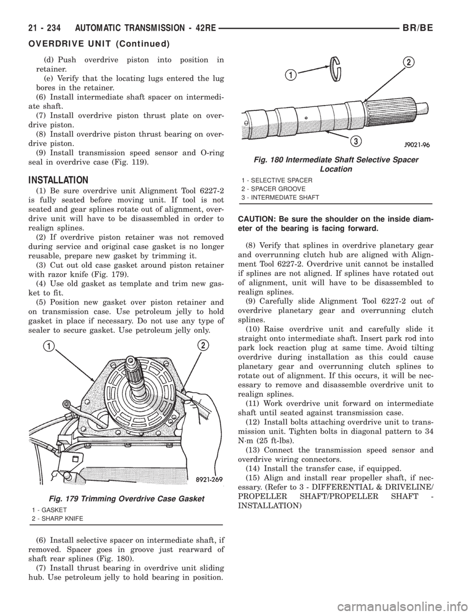
(3) Cut out old case gasket around piston retainer
with razor knife (Fig. 179).
(4) Use old gasket as template and trim new gas-
ket to fit.
(5) Position new gasket over piston retainer and
on transmission case. Use petroleum jelly to hold
gasket in place if necessary. Do not use any type of
sealer to secure gasket. Use petroleum jelly only.
(6) Install selective spacer on intermediate shaft, if
removed. Spacer goes in groove just rearward of
shaft rear splines (Fig. 180).
(7) Install thrust bearing in overdrive unit sliding
hub. Use petroleum jelly to hold bearing in position.CAUTION: Be sure the shoulder on the inside diam-
eter of the bearing is facing forward.
(8) Verify that splines in overdrive planetary gear
and overrunning clutch hub are aligned with Align-
ment Tool 6227-2. Overdrive unit cannot be installed
if splines are not aligned. If splines have rotated out
of alignment, unit will have to be disassembled to
realign splines.
(9) Carefully slide Alignment Tool 6227-2 out of
overdrive planetary gear and overrunning clutch
splines.
(10) Raise overdrive unit and carefully slide it
straight onto intermediate shaft. Insert park rod into
park lock reaction plug at same time. Avoid tilting
overdrive during installation as this could cause
planetary gear and overrunning clutch splines to
rotate out of alignment. If this occurs, it will be nec-
essary to remove and disassemble overdrive unit to
realign splines.
(11) Work overdrive unit forward on intermediate
shaft until seated against transmission case.
(12) Install bolts attaching overdrive unit to trans-
mission unit. Tighten bolts in diagonal pattern to 34
N´m (25 ft-lbs).
(13) Connect the transmission speed sensor and
overdrive wiring connectors.
(14) Install the transfer case, if equipped.
(15) Align and install rear propeller shaft, if nec-
essary. (Refer to 3 - DIFFERENTIAL & DRIVELINE/
PROPELLER SHAFT/PROPELLER SHAFT -
INSTALLATION)
Fig. 179 Trimming Overdrive Case Gasket
1 - GASKET
2 - SHARP KNIFE
Fig. 180 Intermediate Shaft Selective Spacer
Location
1 - SELECTIVE SPACER
2 - SPACER GROOVE
3 - INTERMEDIATE SHAFT
21 - 234 AUTOMATIC TRANSMISSION - 42REBR/BE
OVERDRIVE UNIT (Continued)
Page 2040 of 2889
(7) Install thrust bearing in overdrive unit sliding
hub. Use petroleum jelly to hold bearing in position.
CAUTION: Be sure the shoulder on the inside diam-
eter of the bearing is facing forward.
(8) Verify that splines in overdrive planetary gear
and overrunning clutch hub are aligned with Align-
ment Tool 6227-2. Overdrive unit cannot be installed
if splines are not aligned. If splines have rotated out
of alignment, unit will have to be disassembled to
realign splines.
(9) Carefully slide Alignment Tool 6227-2 out of
overdrive planetary gear and overrunning clutch
splines.
(10) Raise overdrive unit and carefully slide it
straight onto intermediate shaft. Insert park rod into
park lock reaction plug at same time. Avoid tilting
overdrive during installation as this could cause
planetary gear and overrunning clutch splines to
rotate out of alignment. If this occurs, it will be nec-
essary to remove and disassemble overdrive unit to
realign splines.
(11) Work overdrive unit forward on intermediate
shaft until seated against transmission case.
(12) Install bolts attaching overdrive unit to trans-
mission unit. Tighten bolts in diagonal pattern to 34
N´m (25 ft-lbs).
(13) Connect the transmission speed sensor and
overdrive wiring connectors.
(14) Install the transfer case, if equipped.
(15) Align and install rear propeller shaft, if nec-
essary. (Refer to 3 - DIFFERENTIAL & DRIVELINE/
PROPELLER SHAFT/PROPELLER SHAFT -
INSTALLATION)
OVERRUNNING CLUTCH
CAM/OVERDRIVE PISTON
RETAINER
DESCRIPTION
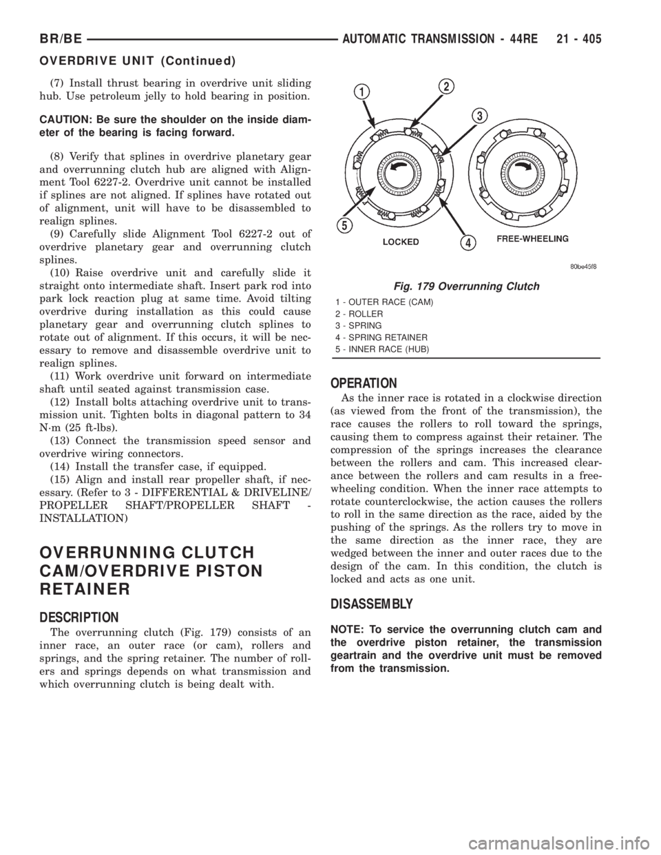
The overrunning clutch (Fig. 179) consists of an
inner race, an outer race (or cam), rollers and
springs, and the spring retainer. The number of roll-
ers and springs depends on what transmission and
which overrunning clutch is being dealt with.
OPERATION
As the inner race is rotated in a clockwise direction
(as viewed from the front of the transmission), the
race causes the rollers to roll toward the springs,
causing them to compress against their retainer. The
compression of the springs increases the clearance
between the rollers and cam. This increased clear-
ance between the rollers and cam results in a free-
wheeling condition. When the inner race attempts to
rotate counterclockwise, the action causes the rollers
to roll in the same direction as the race, aided by the
pushing of the springs. As the rollers try to move in
the same direction as the inner race, they are
wedged between the inner and outer races due to the
design of the cam. In this condition, the clutch is
locked and acts as one unit.
DISASSEMBLY
NOTE: To service the overrunning clutch cam and
the overdrive piston retainer, the transmission
geartrain and the overdrive unit must be removed
from the transmission.
Fig. 179 Overrunning Clutch
1 - OUTER RACE (CAM)
2 - ROLLER
3 - SPRING
4 - SPRING RETAINER
5 - INNER RACE (HUB)
BR/BEAUTOMATIC TRANSMISSION - 44RE 21 - 405
OVERDRIVE UNIT (Continued)
Page 2107 of 2889
BOOST VALVE TUBE AND BRACE
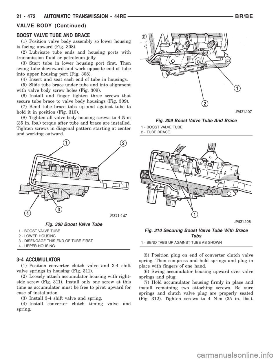
(1) Position valve body assembly so lower housing
is facing upward (Fig. 308).
(2) Lubricate tube ends and housing ports with
transmission fluid or petroleum jelly.
(3) Start tube in lower housing port first. Then
swing tube downward and work opposite end of tube
into upper housing port (Fig. 308).
(4) Insert and seat each end of tube in housings.
(5) Slide tube brace under tube and into alignment
with valve body screw holes (Fig. 309).
(6) Install and finger tighten three screws that
secure tube brace to valve body housings (Fig. 309).
(7) Bend tube brace tabs up and against tube to
hold it in position (Fig. 310).
(8) Tighten all valve body housing screws to 4 N´m
(35 in. lbs.) torque after tube and brace are installed.
Tighten screws in diagonal pattern starting at center
and working outward.
3-4 ACCUMULATOR
(1) Position converter clutch valve and 3-4 shift
valve springs in housing (Fig. 311).
(2) Loosely attach accumulator housing with right-
side screw (Fig. 311). Install only one screw at this
time as accumulator must be free to pivot upward for
ease of installation.
(3) Install 3-4 shift valve and spring.
(4) Install converter clutch timing valve and
spring.(5) Position plug on end of converter clutch valve
spring. Then compress and hold springs and plug in
place with fingers of one hand.
(6) Swing accumulator housing upward over valve
springs and plug.
(7) Hold accumulator housing firmly in place and
install remaining two attaching screws. Be sure
springs and clutch valve plug are properly seated
(Fig. 312). Tighten screws to 4 N´m (35 in. lbs.).
Fig. 308 Boost Valve Tube
1 - BOOST VALVE TUBE
2 - LOWER HOUSING
3 - DISENGAGE THIS END OF TUBE FIRST
4 - UPPER HOUSING
Fig. 309 Boost Valve Tube And Brace
1 - BOOST VALVE TUBE
2 - TUBE BRACE
Fig. 310 Securing Boost Valve Tube With Brace
Tabs
1 - BEND TABS UP AGAINST TUBE AS SHOWN
21 - 472 AUTOMATIC TRANSMISSION - 44REBR/BE
VALVE BODY (Continued)
Page 2213 of 2889
seated and gear splines rotate out of alignment, over-
drive unit will have to be disassembled in order to
realign splines.
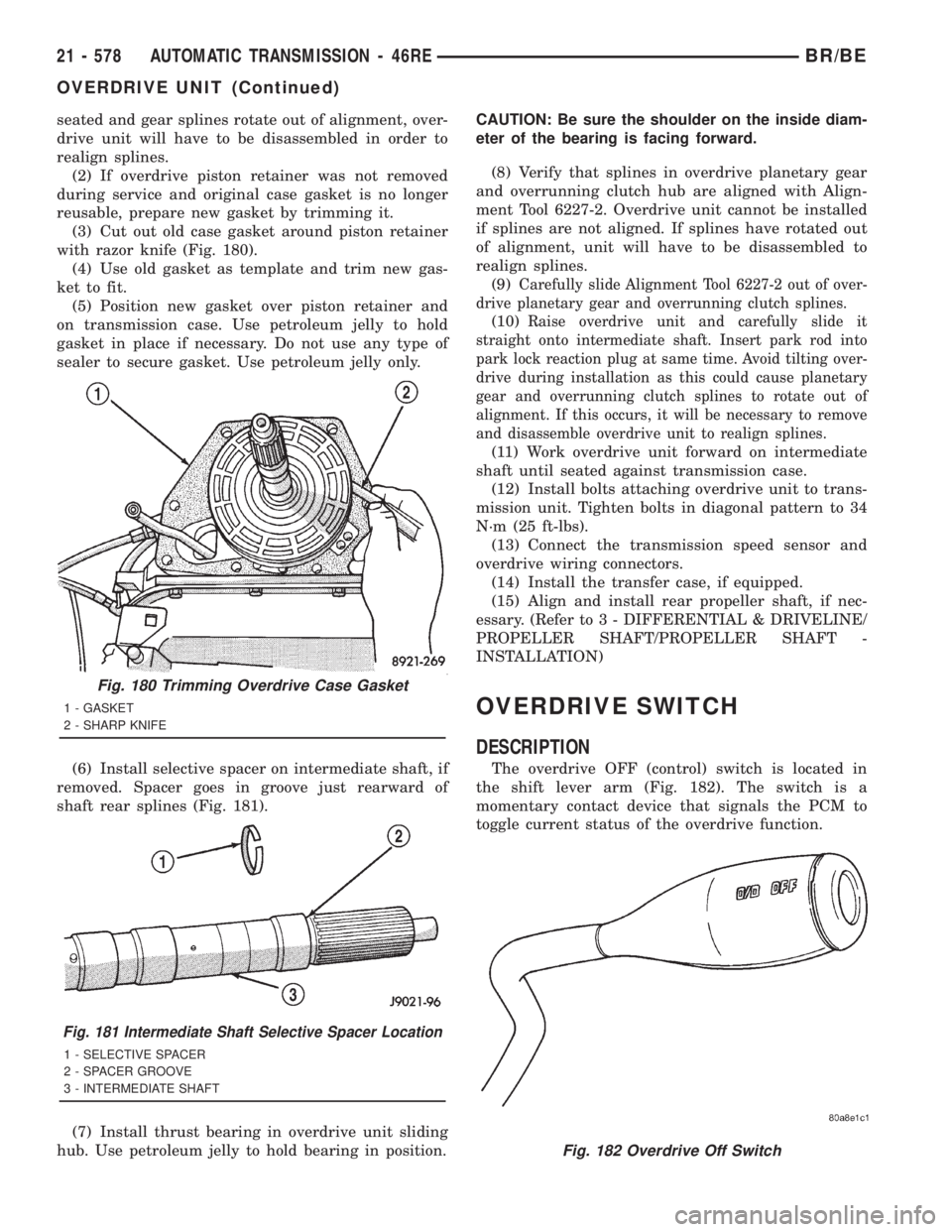
(2) If overdrive piston retainer was not removed
during service and original case gasket is no longer
reusable, prepare new gasket by trimming it.
(3) Cut out old case gasket around piston retainer
with razor knife (Fig. 180).
(4) Use old gasket as template and trim new gas-
ket to fit.
(5) Position new gasket over piston retainer and
on transmission case. Use petroleum jelly to hold
gasket in place if necessary. Do not use any type of
sealer to secure gasket. Use petroleum jelly only.
(6) Install selective spacer on intermediate shaft, if
removed. Spacer goes in groove just rearward of
shaft rear splines (Fig. 181).
(7) Install thrust bearing in overdrive unit sliding
hub. Use petroleum jelly to hold bearing in position.CAUTION: Be sure the shoulder on the inside diam-
eter of the bearing is facing forward.
(8) Verify that splines in overdrive planetary gear
and overrunning clutch hub are aligned with Align-
ment Tool 6227-2. Overdrive unit cannot be installed
if splines are not aligned. If splines have rotated out
of alignment, unit will have to be disassembled to
realign splines.
(9)
Carefully slide Alignment Tool 6227-2 out of over-
drive planetary gear and overrunning clutch splines.
(10)Raise overdrive unit and carefully slide it
straight onto intermediate shaft. Insert park rod into
park lock reaction plug at same time. Avoid tilting over-
drive during installation as this could cause planetary
gear and overrunning clutch splines to rotate out of
alignment. If this occurs, it will be necessary to remove
and disassemble overdrive unit to realign splines.
(11) Work overdrive unit forward on intermediate
shaft until seated against transmission case.
(12) Install bolts attaching overdrive unit to trans-
mission unit. Tighten bolts in diagonal pattern to 34
N´m (25 ft-lbs).
(13) Connect the transmission speed sensor and
overdrive wiring connectors.
(14) Install the transfer case, if equipped.
(15) Align and install rear propeller shaft, if nec-
essary. (Refer to 3 - DIFFERENTIAL & DRIVELINE/
PROPELLER SHAFT/PROPELLER SHAFT -
INSTALLATION)
OVERDRIVE SWITCH
DESCRIPTION
The overdrive OFF (control) switch is located in
the shift lever arm (Fig. 182). The switch is a
momentary contact device that signals the PCM to
toggle current status of the overdrive function.
Fig. 180 Trimming Overdrive Case Gasket
1 - GASKET
2 - SHARP KNIFE
Fig. 181 Intermediate Shaft Selective Spacer Location
1 - SELECTIVE SPACER
2 - SPACER GROOVE
3 - INTERMEDIATE SHAFT
Fig. 182 Overdrive Off Switch
21 - 578 AUTOMATIC TRANSMISSION - 46REBR/BE
OVERDRIVE UNIT (Continued)
Page 2386 of 2889
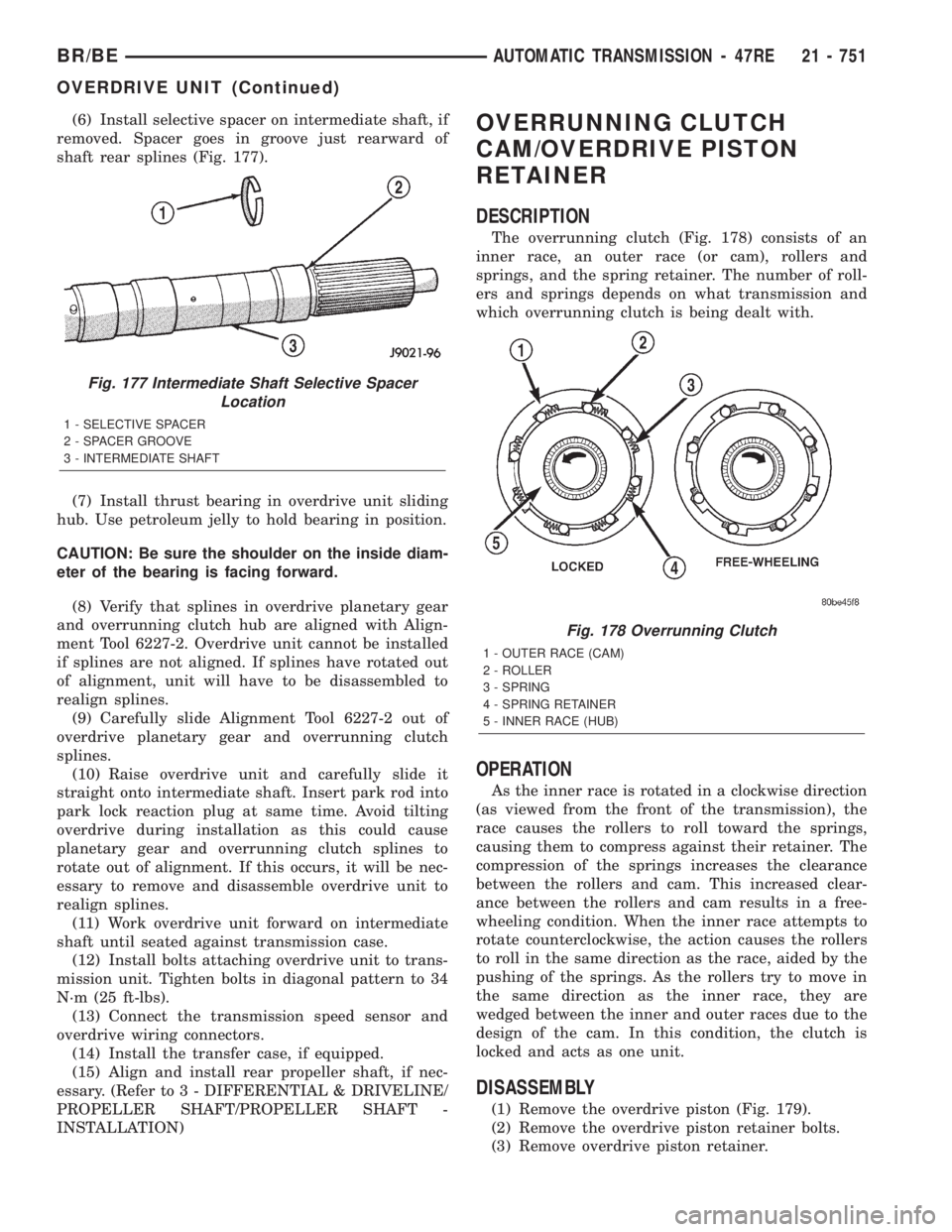
(6) Install selective spacer on intermediate shaft, if
removed. Spacer goes in groove just rearward of
shaft rear splines (Fig. 177).
(7) Install thrust bearing in overdrive unit sliding
hub. Use petroleum jelly to hold bearing in position.
CAUTION: Be sure the shoulder on the inside diam-
eter of the bearing is facing forward.
(8) Verify that splines in overdrive planetary gear
and overrunning clutch hub are aligned with Align-
ment Tool 6227-2. Overdrive unit cannot be installed
if splines are not aligned. If splines have rotated out
of alignment, unit will have to be disassembled to
realign splines.
(9) Carefully slide Alignment Tool 6227-2 out of
overdrive planetary gear and overrunning clutch
splines.
(10) Raise overdrive unit and carefully slide it
straight onto intermediate shaft. Insert park rod into
park lock reaction plug at same time. Avoid tilting
overdrive during installation as this could cause
planetary gear and overrunning clutch splines to
rotate out of alignment. If this occurs, it will be nec-
essary to remove and disassemble overdrive unit to
realign splines.
(11) Work overdrive unit forward on intermediate
shaft until seated against transmission case.
(12) Install bolts attaching overdrive unit to trans-
mission unit. Tighten bolts in diagonal pattern to 34
N´m (25 ft-lbs).
(13) Connect the transmission speed sensor and
overdrive wiring connectors.
(14) Install the transfer case, if equipped.
(15) Align and install rear propeller shaft, if nec-
essary. (Refer to 3 - DIFFERENTIAL & DRIVELINE/
PROPELLER SHAFT/PROPELLER SHAFT -
INSTALLATION)OVERRUNNING CLUTCH
CAM/OVERDRIVE PISTON
RETAINER
DESCRIPTION
The overrunning clutch (Fig. 178) consists of an
inner race, an outer race (or cam), rollers and
springs, and the spring retainer. The number of roll-
ers and springs depends on what transmission and
which overrunning clutch is being dealt with.
OPERATION
As the inner race is rotated in a clockwise direction
(as viewed from the front of the transmission), the
race causes the rollers to roll toward the springs,
causing them to compress against their retainer. The
compression of the springs increases the clearance
between the rollers and cam. This increased clear-
ance between the rollers and cam results in a free-
wheeling condition. When the inner race attempts to
rotate counterclockwise, the action causes the rollers
to roll in the same direction as the race, aided by the
pushing of the springs. As the rollers try to move in
the same direction as the inner race, they are
wedged between the inner and outer races due to the
design of the cam. In this condition, the clutch is
locked and acts as one unit.
DISASSEMBLY
(1) Remove the overdrive piston (Fig. 179).
(2) Remove the overdrive piston retainer bolts.
(3) Remove overdrive piston retainer.
Fig. 177 Intermediate Shaft Selective Spacer
Location
1 - SELECTIVE SPACER
2 - SPACER GROOVE
3 - INTERMEDIATE SHAFT
Fig. 178 Overrunning Clutch
1 - OUTER RACE (CAM)
2 - ROLLER
3 - SPRING
4 - SPRING RETAINER
5 - INNER RACE (HUB)
BR/BEAUTOMATIC TRANSMISSION - 47RE 21 - 751
OVERDRIVE UNIT (Continued)
Page 2449 of 2889
(10) Install shuttle valve primary spring and
throttle plug.
(11) Align and install governor plug cover. Tighten
cover screws to 4 N´m (35 in. lbs.) torque.
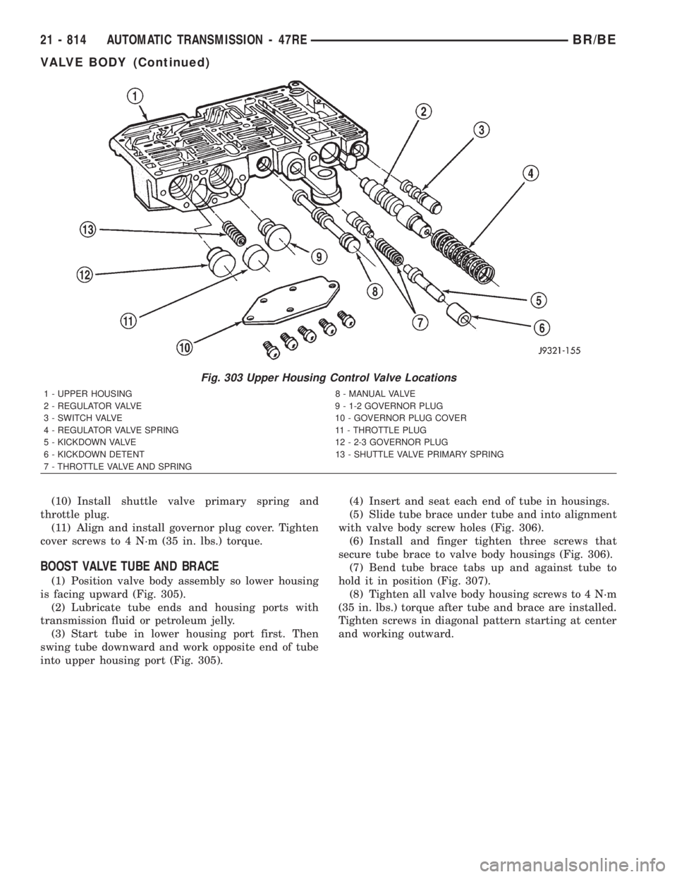
BOOST VALVE TUBE AND BRACE
(1) Position valve body assembly so lower housing
is facing upward (Fig. 305).
(2) Lubricate tube ends and housing ports with
transmission fluid or petroleum jelly.
(3) Start tube in lower housing port first. Then
swing tube downward and work opposite end of tube
into upper housing port (Fig. 305).(4) Insert and seat each end of tube in housings.
(5) Slide tube brace under tube and into alignment
with valve body screw holes (Fig. 306).
(6) Install and finger tighten three screws that
secure tube brace to valve body housings (Fig. 306).
(7) Bend tube brace tabs up and against tube to
hold it in position (Fig. 307).
(8) Tighten all valve body housing screws to 4 N´m
(35 in. lbs.) torque after tube and brace are installed.
Tighten screws in diagonal pattern starting at center
and working outward.
Fig. 303 Upper Housing Control Valve Locations
1 - UPPER HOUSING 8 - MANUAL VALVE
2 - REGULATOR VALVE 9 - 1-2 GOVERNOR PLUG
3 - SWITCH VALVE 10 - GOVERNOR PLUG COVER
4 - REGULATOR VALVE SPRING 11 - THROTTLE PLUG
5 - KICKDOWN VALVE 12 - 2-3 GOVERNOR PLUG
6 - KICKDOWN DETENT 13 - SHUTTLE VALVE PRIMARY SPRING
7 - THROTTLE VALVE AND SPRING
21 - 814 AUTOMATIC TRANSMISSION - 47REBR/BE
VALVE BODY (Continued)
Page 2527 of 2889
PTO CAPABILITY
The NV241HD transfer case has power take-off
capability. A PTO gear permanently attached to the
planetary carrier, and a removable PTO cover are
provided for this purpose.
IDENTIFICATION
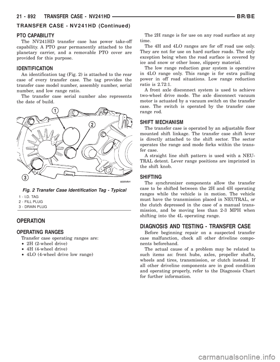
An identification tag (Fig. 2) is attached to the rear
case of every transfer case. The tag provides the
transfer case model number, assembly number, serial
number, and low range ratio.
The transfer case serial number also represents
the date of build.
OPERATION
OPERATING RANGES
Transfer case operating ranges are:
²2H (2-wheel drive)
²4H (4-wheel drive)
²4LO (4-wheel drive low range)The 2H range is for use on any road surface at any
time.
The 4H and 4LO ranges are for off road use only.
They are not for use on hard surface roads. The only
exception being when the road surface is covered by
ice and snow or other loose, slippery material.
The low range reduction gear system is operative
in 4LO range only. This range is for extra pulling
power in off road situations. Low range reduction
ratio is 2.72:1.
A front axle disconnect system is used to achieve
two-wheel drive mode. The axle disconnect vacuum
motor is actuated by a vacuum switch on the transfer
case. The switch is operated by the transfer case
range rod.
SHIFT MECHANISM
The transfer case is operated by an adjustable floor
mounted shift linkage. The transfer case shift lever
is directly attached to the shift sector. The sector
operates the range and mode forks within the trans-
fer case.
A straight line shift pattern is used with a NEU-
TRAL detent. Lever range positions are imprinted in
the shift knob.
SHIFTING
The synchronizer components allow the transfer
case to be shifted between the 2H and 4H operating
ranges while the vehicle is in motion. The vehicle
must have the transmission placed in NEUTRAL, or
the clutch depressed in the case of a manual trans-
mission, and be moving less than 2-3 MPH when
shifting into the 4L operating range.
DIAGNOSIS AND TESTING - TRANSFER CASE
Before beginning repair on a suspected transfer
case malfunction, check all other driveline compo-
nents beforehand.
The actual cause of a problem may be related to
such items as: front hubs, axles, propeller shafts,
wheels and tires, transmission, or clutch instead. If
all other driveline components are in good condition
and operating properly, refer to the Diagnosis Chart
for further information.
Fig. 2 Transfer Case Identification Tag - Typical
1 - I.D. TAG
2 - FILL PLUG
3 - DRAIN PLUG
21 - 892 TRANSFER CASE - NV241HDBR/BE
TRANSFER CASE - NV241HD (Continued)
Page 2571 of 2889
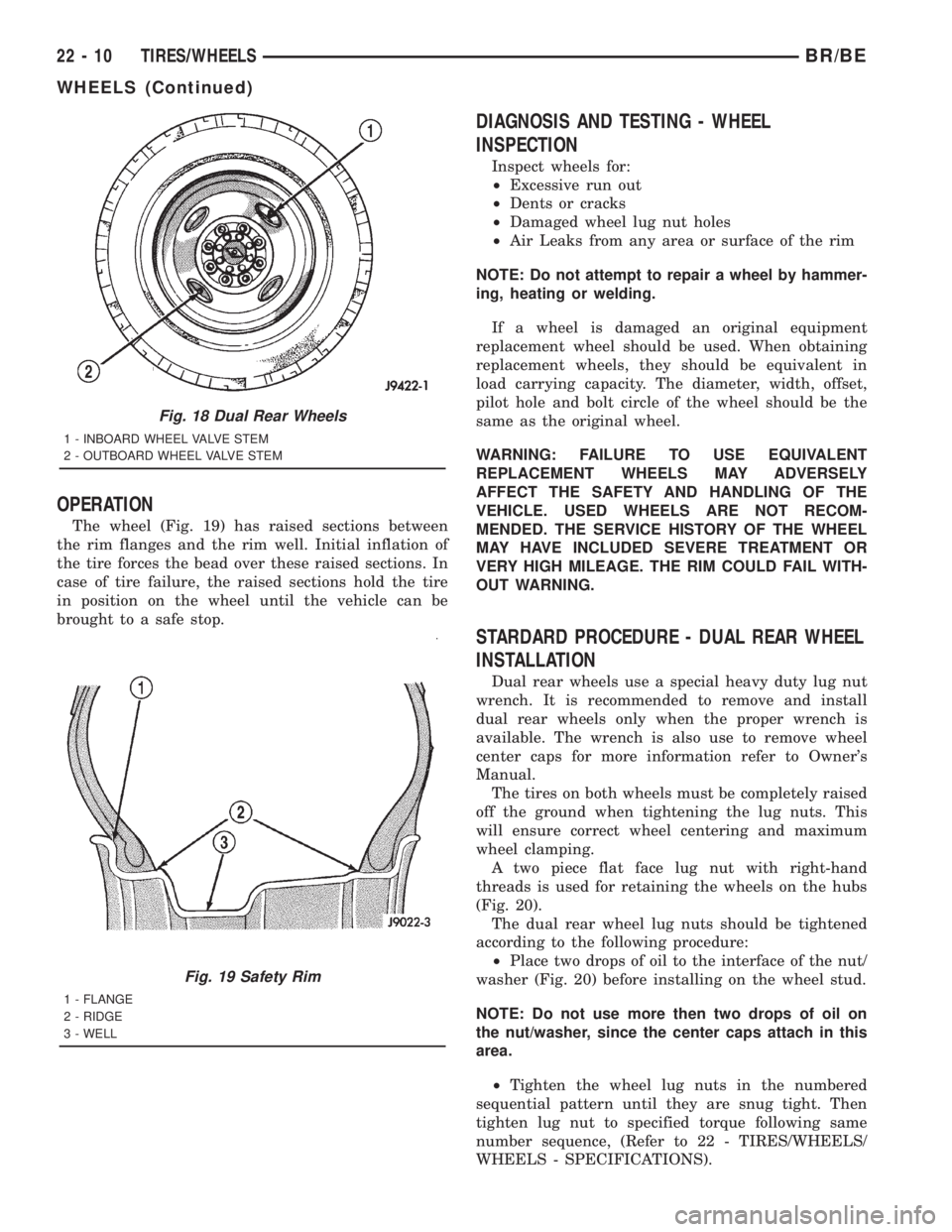
OPERATION
The wheel (Fig. 19) has raised sections between
the rim flanges and the rim well. Initial inflation of
the tire forces the bead over these raised sections. In
case of tire failure, the raised sections hold the tire
in position on the wheel until the vehicle can be
brought to a safe stop.
DIAGNOSIS AND TESTING - WHEEL
INSPECTION
Inspect wheels for:
²Excessive run out
²Dents or cracks
²Damaged wheel lug nut holes
²Air Leaks from any area or surface of the rim
NOTE: Do not attempt to repair a wheel by hammer-
ing, heating or welding.
If a wheel is damaged an original equipment
replacement wheel should be used. When obtaining
replacement wheels, they should be equivalent in
load carrying capacity. The diameter, width, offset,
pilot hole and bolt circle of the wheel should be the
same as the original wheel.
WARNING: FAILURE TO USE EQUIVALENT
REPLACEMENT WHEELS MAY ADVERSELY
AFFECT THE SAFETY AND HANDLING OF THE
VEHICLE. USED WHEELS ARE NOT RECOM-
MENDED. THE SERVICE HISTORY OF THE WHEEL
MAY HAVE INCLUDED SEVERE TREATMENT OR
VERY HIGH MILEAGE. THE RIM COULD FAIL WITH-
OUT WARNING.
STARDARD PROCEDURE - DUAL REAR WHEEL
INSTALLATION
Dual rear wheels use a special heavy duty lug nut
wrench. It is recommended to remove and install
dual rear wheels only when the proper wrench is
available. The wrench is also use to remove wheel
center caps for more information refer to Owner's
Manual.
The tires on both wheels must be completely raised
off the ground when tightening the lug nuts. This
will ensure correct wheel centering and maximum
wheel clamping.
A two piece flat face lug nut with right-hand
threads is used for retaining the wheels on the hubs
(Fig. 20).
The dual rear wheel lug nuts should be tightened
according to the following procedure:
²Place two drops of oil to the interface of the nut/
washer (Fig. 20) before installing on the wheel stud.
NOTE: Do not use more then two drops of oil on
the nut/washer, since the center caps attach in this
area.
²Tighten the wheel lug nuts in the numbered
sequential pattern until they are snug tight. Then
tighten lug nut to specified torque following same
number sequence, (Refer to 22 - TIRES/WHEELS/
WHEELS - SPECIFICATIONS).
Fig. 18 Dual Rear Wheels
1 - INBOARD WHEEL VALVE STEM
2 - OUTBOARD WHEEL VALVE STEM
Fig. 19 Safety Rim
1 - FLANGE
2 - RIDGE
3 - WELL
22 - 10 TIRES/WHEELSBR/BE
WHEELS (Continued)
Page 2872 of 2889
PARK/TURN SIGNAL LAMP -
INSTALLATION.......................8L-29
PARK/TURN SIGNAL LAMP - REMOVAL . . . 8L-29
PARK/TURN SIGNAL LAMP UNIT -
INSTALLATION.......................8L-29
PARK/TURN SIGNAL LAMP UNIT -
REMOVAL..........................8L-29
PARTS - STANDARD PROCEDURES,
CLEANING FUEL SYSTEM..............14-57
PASSENGER AIRBAG - DESCRIPTION....8O-21
PASSENGER AIRBAG - INSTALLATION....8O-23
PASSENGER AIRBAG - OPERATION......8O-21
PASSENGER AIRBAG - REMOVAL........8O-21
PASSENGER AIRBAG ON/OFF SWITCH -
DESCRIPTION.......................8O-23
PASSENGER AIRBAG ON/OFF SWITCH -
INSTALLATION......................8O-25
PASSENGER AIRBAG ON/OFF SWITCH -
OPERATION.........................8O-24
PASSENGER AIRBAG ON/OFF SWITCH -
REMOVAL..........................8O-24
PASSENGER POWER SEAT SWITCH -
DESCRIPTION.......................8N-19
PASSENGER POWER SEAT SWITCH -
DIAGNOSIS & TESTING...............8N-19
PASSENGER POWER SEAT SWITCH -
INSTALLATION......................8N-20
PASSENGER POWER SEAT SWITCH -
OPERATION.........................8N-19
PASSENGER POWER SEAT SWITCH -
REMOVAL..........................8N-20
PASSENGER SEAT HEATER SWITCH -
DESCRIPTION.......................8G-13
PASSENGER SEAT HEATER SWITCH -
INSTALLATION......................8G-16
PASSENGER SEAT HEATER SWITCH -
OPERATION.........................8G-14
PASSENGER SEAT HEATER SWITCH -
REMOVAL..........................8G-15
PATTERNS - DIAGNOSIS AND TESTING,
TIRE WEAR..........................22-7
PCM - DESCRIPTION..................8E-14
PCM - GAS ENGINES - OPERATION......8E-17
PCM INPUT - OPERATION, ASD SENSE.....8I-3
PCM OUTPUT - DESCRIPTION............8I-3
PCM OUTPUT - OPERATION............14-53
PCM OUTPUT - OPERATION.............8I-3
PCV FILTER - DESCRIPTION............25-35
PCV VALVE - V-6/V-8 ENGINES -
DIAGNOSIS AND TESTING.............25-36
PEDAL - DESCRIPTION.................5-16
PEDAL - INSTALLATION............5-17,5-36
PEDAL - INSTALLATION, ACCELERATOR . . . 14-37
PEDAL - INSTALLATION, CLUTCH.........6-19
PEDAL - OPERATION...................5-16
PEDAL - REMOVAL................5-16,5-36
PEDAL - REMOVAL, ACCELERATOR......14-37
PEDAL - REMOVAL, CLUTCH............6-18
PEDAL POSITION SENSOR -
DESCRIPTION, ACCELERATOR..........14-91
PEDAL POSITION SENSOR -
INSTALLATION, ACCELERATOR..........14-93
PEDAL POSITION SENSOR - OPERATION,
ACCELERATOR.......................14-91
PEDAL POSITION SENSOR - REMOVAL,
ACCELERATOR.......................14-91
PEDAL POSITION SWITCH -
DESCRIPTION, CLUTCH.................6-22
PEDAL POSITION SWITCH - OPERATION,
CLUTCH.............................6-22
PER MILE, SPECIFICATIONS - TIRE
REVOLUTIONS........................22-9
PERFORMANCE - DIAGNOSIS AND
TESTING...............9-118,9-173,9-4,9-61
PERFORMANCE - DIAGNOSIS AND
TESTING, A/C........................24-2
PERFORMANCE - DIAGNOSIS AND
TESTING, HEATER.....................24-6
PERFORMANCE - INSPECTION, ENGINE . . . 30-16
PILOT BEARING - DESCRIPTION..........6-17
PILOT BEARING - INSTALLATION.........6-18
PILOT BEARING - OPERATION
...........6-18
PILOT BEARING - REMOVAL
.............6-18
PINION GEAR/RING GEAR -
INSTALLATION
....................3-42,3-74
PINION GEAR/RING GEAR - REMOVAL
. 3-40,3-72
PINION GEAR/RING GEAR/TONE RING -
INSTALLATION
........3-105,3-137,3-166,3-195PINION GEAR/RING GEAR/TONE RING -
REMOVAL...........3-103,3-135,3-165,3-193
PINION SEAL - INSTALLATION.....3-125,3-157,
3-185,3-34,3-66,3-95
PINION SEAL - REMOVAL . . . 3-125,3-156,3-185,
3-34,3-66,3-95
PIPE - 3.9L/5.2L/5.9L - INSPECTION,
EXHAUST............................11-7
PIPE - 3.9L/5.2L/5.9L - INSTALLATION,
EXHAUST............................11-7
PIPE - 3.9L/5.2L/5.9L - REMOVAL,
EXHAUST............................11-7
PIPE - 5.9L DIESEL - INSPECTION,
EXHAUST............................11-9
PIPE - 5.9L DIESEL - INSTALLATION,
EXHAUST...........................11-10
PIPE - 5.9L DIESEL - REMOVAL,
EXHAUST............................11-9
PIPE - 5.9L HEAVY DUTY/8.0L -
INSPECTION, EXHAUST.................11-9
PIPE - 5.9L HEAVY DUTY/8.0L -
INSTALLATION, EXHAUST...............11-9
PIPE - 5.9L HEAVY DUTY/8.0L -
REMOVAL, EXHAUST...................11-8
PISTON & CONNECTING ROD -
CLEANING........9-154,9-209,9-285,9-41,9-98
PISTON & CONNECTING ROD -
CONNECTING RODS..................9-286
PISTON & CONNECTING ROD -
DESCRIPTION.....9-153,9-208,9-282,9-40,9-97
PISTON & CONNECTING ROD -
INSPECTION......9-154,9-209,9-285,9-41,9-98
PISTON & CONNECTING ROD -
INSTALLATION......9-154,9-210,9-287,9-41,9-98
PISTON & CONNECTING ROD -
REMOVAL........9-154,9-209,9-285,9-40,9-97
PISTON FITTING - STANDARD
PROCEDURE...........9-153,9-208,9-40,9-97
PISTON GRADING - STANDARD
PROCEDURE........................9-282
PISTON RETAINER - ASSEMBLY,
OVERRUNNING CLUTCH CAM/
OVERDRIVE
......21-236,21-406,21-581,21-752
PISTON RETAINER - CLEANING,
OVERRUNNING CLUTCH CAM/
OVERDRIVE
......21-236,21-406,21-580,21-752
PISTON RETAINER - DESCRIPTION,
OVERRUNNING CLUTCH CAM/
OVERDRIVE
......21-235,21-405,21-580,21-751
PISTON RETAINER - DISASSEMBLY,
OVERRUNNING CLUTCH CAM/
OVERDRIVE
......21-235,21-405,21-580,21-751
PISTON RETAINER - INSPECTION,
OVERRUNNING CLUTCH CAM/
OVERDRIVE
......21-236,21-406,21-580,21-752
PISTON RETAINER - OPERATION,
OVERRUNNING CLUTCH CAM/
OVERDRIVE
......21-235,21-405,21-580,21-751
PISTON RING FITTING - STANDARD
PROCEDURE
................9-154,9-41,9-98
PISTON RINGS - STANDARD
PROCEDURE, FITTING
.................9-211
PISTON RINGS - STANDARD
PROCEDURE-PISTON RING FITTING
......9-288
PISTONS - DESCRIPTION
. 21-238,21-408,21-584,
21-755
PISTONS - OPERATION
. . 21-238,21-409,21-584,
21-755
PITMAN BEARING - INSTALLATION
......19-21
PITMAN BEARING - REMOVAL
..........19-20
PITMAN SHAFT - INSTALLATION
........19-23
PITMAN SHAFT - REMOVAL
............19-22
PITMAN SHAFT SEAL - INSTALLATION
....19-24
PITMAN SHAFT SEAL - REMOVAL
.......19-23
PLANETARY GEARTRAIN/OUTPUT
SHAFT - ASSEMBLY
.....21-241,21-412,21-588,
21-760
PLANETARY GEARTRAIN/OUTPUT
SHAFT - DESCRIPTION
. . . 21-240,21-410,21-585,
21-757
PLANETARY GEARTRAIN/OUTPUT
SHAFT - DISASSEMBLY
. . 21-240,21-411,21-586,
21-757
PLANETARY GEARTRAIN/OUTPUT
SHAFT - INSPECTION
....21-241,21-411,21-587,
21-760PLANETARY GEARTRAIN/OUTPUT
SHAFT - OPERATION....21-240,21-410,21-585,
21-757
PLATE - DESCRIPTION, BODY CODE....Intro.-1
PLATE - DESCRIPTION, ENGINE DATA....9-244
PLATE - DESCRIPTION, EQUIPMENT
IDENTIFICATION...................Intro.-12
PLATE - DESCRIPTION, PRESSURE.......6-15
PLATE - INSTALLATION, SUPPORT........5-32
PLATE - INSTALLATION, TRANSFER
CASE SKID.........................13-11
PLATE - OPERATION, PRESSURE.........6-16
PLATE - REMOVAL, SUPPORT...........5-32
PLATE - REMOVAL, TRANSFER CASE
SKID..............................13-11
PLATE LAMP - INSTALLATION, LICENSE . . 8L-22
PLATE LAMP - REMOVAL, LICENSE......8L-22
PLATE LAMP UNIT - INSTALLATION,
LICENSE...........................8L-22
PLATE LAMP UNIT - REMOVAL, LICENSE . . 8L-22
PLATE, SPECIFICATIONS - FUEL
INJECTION PUMP DATA...............14-73
PLATES - INSTALLATION, EXTERIOR
NAME.............................23-89
PLATES - REMOVAL, EXTERIOR NAME....23-89
PLUG - CLEANING, SPARK.............8I-19
PLUG - DESCRIPTION, SPARK...........8I-16
PLUG - INSTALLATION, SPARK..........8I-19
PLUG - INSTALLATION, STEERING GEAR
HOUSING............................19-27
PLUG - OPERATION, SPARK............8I-16
PLUG - REMOVAL, SPARK..............8I-18
PLUG - REMOVAL, STEERING GEAR
HOUSING...........................19-27
PLUG CABLE - DESCRIPTION, SPARK.....8I-19
PLUG CABLE - INSTALLATION, SPARK....8I-20
PLUG CABLE - OPERATION, SPARK.......8I-19
PLUG CABLE - REMOVAL, SPARK........8I-20
PLUG CABLE ORDER, 8.0L V-10 ENGINE
- SPARK .............................8I-2
PLUG CABLE RESISTANCE,
SPECIFICATIONS - SPARK...............8I-3
PLUG CABLES - DIAGNOSIS AND
TESTING, SPARK.....................8I-19
PLUG CONDITIONS - DIAGNOSIS AND
TESTING, SPARK.....................8I-16
PLUGS, SPECIFICATIONS - SPARK........8I-3
PLUMBING - CLEANING, CHARGE AIR
COOLER............................11-18
PLUMBING - DESCRIPTION............24-40
PLUMBING - DESCRIPTION, CHARGE
AIR COOLER........................11-17
PLUMBING - INSPECTION, CHARGE AIR
COOLER............................11-18
PLUMBING - INSTALLATION, CHARGE
AIR COOLER........................11-18
PLUMBING - OPERATION..............24-41
PLUMBING - OPERATION, CHARGE AIR
COOLER............................11-17
PLUMBING - REMOVAL, CHARGE AIR
COOLER............................11-17
POLISHING - DESCRIPTION, WET
SANDING/BUFFING..................23-130
PORT - DESCRIPTION, REFRIGERANT
SYSTEM SERVICE.....................24-1
PORT - OPERATION, REFRIGERANT
SYSTEM SERVICE.....................24-2
POSITION SENSOR - DESCRIPTION,
ACCELERATOR PEDAL.................14-91
POSITION SENSOR - DESCRIPTION,
THROTTLE..........................14-51
POSITION SENSOR - INSTALLATION,
ACCELERATOR PEDAL.................14-93
POSITION SENSOR - OPERATION,
ACCELERATOR PEDAL.................14-91
POSITION SENSOR - OPERATION,
THROTTLE..........................14-51
POSITION SENSOR - REMOVAL,
ACCELERATOR PEDAL
.................14-91
POSITION SWITCH - DESCRIPTION,
CLUTCH PEDAL
.......................6-22
POSITION SWITCH - DIAGNOSIS AND
TESTING, PARK/NEUTRAL
......21-237,21-408,
21-583,21-755
POSITION SWITCH - INSTALLATION,
PARK/NEUTRAL
. . . 21-238,21-408,21-583,21-755
POSITION SWITCH - OPERATION,
CLUTCH PEDAL
.......................6-22
BR/BEINDEX 25
Description Group-Page Description Group-Page Description Group-Page