clock setting DODGE RAM 2001 Service Repair Manual
[x] Cancel search | Manufacturer: DODGE, Model Year: 2001, Model line: RAM, Model: DODGE RAM 2001Pages: 2889, PDF Size: 68.07 MB
Page 425 of 2889
Refer to Electrical, Restraints for more information
on the clockspring. Refer to Electrical, Body Control/
Central Control Module for more information on the
Central Timer Module. Refer to the appropriate wir-
ing information. The wiring information includes wir-
ing diagrams, proper wire and connector repair
procedures, details of wire harness routing and
retention, connector pin-out information and location
views for the various wire harness connectors, splices
and grounds. Following are general descriptions of
the remaining major components in the standard and
optional factory-installed audio systems.
OPERATION
See the owner's manual in the vehicle glove box for
more information on the features, use and operation
of each of the available audio systems.
CENTRAL TIMER MODULE
The high-line or premium Central Timer Module
(CTM) can also control some features of the audio
system when the vehicle is equipped with the
optional RAZ radio receiver and remote radio
switches. A high-line CTM is used on high-line ver-
sions of this vehicle. A premium CTM is used on
vehicles equipped with the optional heated seats. The
CTM combines the functions of a chime/buzzer mod-
ule, an intermittent wipe module, an illuminated
entry module, a remote keyless entry module, and a
vehicle theft security system module in a single unit.
The high-line or premium CTM also controls and
integrates many of the additional electronic functions
and features included on models with this option.The RAZ radio receiver with a remote radio switch
option is one of the features that the CTM controls.
The CTM is programmed to send switch status mes-
sages over the Chrysler Collision Detection (CCD)
data bus to control the volume, seek, and pre-set sta-
tion advance functions of the RAZ radio receiver. The
CTM monitors the status of the remote radio
switches located on the steering wheel through a
hard wired circuit. The CTM then sends the proper
switch status messages to the radio receiver. The
electronic circuitry within the radio receiver responds
to the switch status messages it receives by adjusting
the radio settings as requested.
Refer to Electrical, Body Control/Central Timer
Module for more information on the high-line CTM.
Refer to Remote Radio Switch in Description and
Operation for more information on this component.
In addition, radio receivers connected to the CCD
data bus have several audio system functions that
can be diagnosed using a DRBIIItscan tool. Refer to
the proper Diagnostic Procedures manual for more
information on DRBIIIttesting of the audio systems.
DIAGNOSIS AND TESTING - AUDIO
WARNING: ON VEHICLES EQUIPPED WITH AIR-
BAGS, REFER TO ELECTRICAL, RESTRAINTS
BEFORE ATTEMPTING ANY STEERING WHEEL,
STEERING COLUMN, OR INSTRUMENT PANEL
COMPONENT DIAGNOSIS OR SERVICE. FAILURE
TO TAKE THE PROPER PRECAUTIONS COULD
RESULT IN ACCIDENTAL AIRBAG DEPLOYMENT
AND POSSIBLE PERSONAL INJURY.
8A - 2 AUDIOBR/BE
AUDIO (Continued)
Page 433 of 2889
(7) Remove the radio receiver from the instrument
panel. Refer to Audio, Radio for the procedures.
(8) Pull the antenna cable out through the radio
receiver opening in the instrument panel.
(9) Untie the cord or twine from the instrument
panel antenna cable connector, leaving the cord or
twine in place of the cable in the instrument panel.
(10) Remove the antenna cable from the instru-
ment panel.
INSTALLATION
(1) Tie the end of the cord or twine that was used
during instrument panel antenna cable removal
securely to the connector on the end of the antenna
cable being installed into the instrument panel. This
cord will be used to pull or ªfishº the cable back into
position.
(2) Using the cord or twine, pull the antenna cable
through the radio receiver opening from under the
instrument panel.
(3) Install the radio receiver onto the instrument
panel. Refer to Audio, Radio for the procedures.
(4) Reach through the glove box opening to engage
the antenna cable with the retainer clips on the back
of the instrument panel.
(5) Install the glove box onto the instrument panel.
Refer to Body, Instrument Panel for the procedures.
(6) Untie the cord or twine from the instrument
panel antenna cable connector.
(7) Reach under the passenger side of the instru-
ment panel near the right cowl side inner panel to
reconnect the two halves of the radio antenna coaxial
cable connector. Wrap the connection with a piece of
foam tape.
(8) Engage the coaxial cable connector with the
retainer clip located on the bottom of the heater-A/C
housing.
(9) Reconnect the battery negative cable.
RADIO
DESCRIPTION
Available factory-installed radio receivers for this
model include an AM/FM/cassette (RAS sales code),
an AM/FM/cassette/5-band graphic equalizer with CD
changer control feature (RBN sales code), an AM/FM/
CD/3-band graphic equalizer (RBR sales code), or an
AM/FM/CD/cassette/3-band graphic equalizer (RAZ
sales code). The factory-installed RAZ sales code
radio receivers can also communicate on the Chrysler
Collision Detection (CCD) data bus network through
a separate two-way wire harness connector. All facto-
ry-installed receivers are stereo Electronically Tuned
Radios (ETR) and include an electronic digital clock
function.These radio receivers can only be serviced by an
authorized radio repair station. See the latest War-
ranty Policies and Procedures manual for a current
listing of authorized radio repair stations.
All vehicles are equipped with an Ignition-Off
Draw (IOD) fuse that is removed when the vehicle is
shipped from the factory. This fuse feeds various
accessories that require battery current when the
ignition switch is in the Off position, including the
clock. The IOD fuse is removed to prevent battery
discharge during vehicle storage.
When removing or installing the IOD fuse, it is
important that the ignition switch be in the Off posi-
tion. Failure to place the ignition switch in the Off
position can cause the radio display to become scram-
bled when the IOD fuse is removed and replaced.
Removing and replacing the IOD fuse again, with the
ignition switch in the Off position, will correct the
scrambled display condition.
The IOD fuse should be checked if the radio or
clock displays are inoperative. The IOD fuse is
located in the junction block. Refer to the fuse layout
label on the back of the instrument panel fuse access
panel for IOD fuse identification and location.
OPERATION
The radio receiver operates on fused battery cur-
rent that is available only when the ignition switch is
in the On or Accessory positions. The electronic digi-
tal clock function of the radio operates on fused bat-
tery current supplied through the IOD fuse,
regardless of the ignition switch position.
For more information on the features, setting pro-
cedures, and control functions for each of the avail-
able factory-installed radio receivers, see the owner's
manual in the vehicle glove box. For complete circuit
diagrams, refer to the appropriate wiring informa-
tion. The wiring information includes wiring dia-
grams, proper wire and connector repair procedures,
details of wire harness routing and retention, connec-
tor pin-out information and location views for the
various wire harness connectors, splices and grounds.
DIAGNOSIS AND TESTING
DIAGNOSIS AND TESTING - RADIO
If the vehicle is equipped with the optional remote
radio switches located on the steering wheel and the
problem being diagnosed is related to one of the
symptoms listed below, be certain to check the
remote radio switches and circuits. Refer to Audio,
Remote Radio Switch prior to attempting radio diag-
nosis or repair.
²Stations changing with no remote radio switch
input
8A - 10 AUDIOBR/BE
INSTRUMENT PANEL ANTENNA CABLE (Continued)
Page 438 of 2889
(6) Remove the heater core ground strap from the
top of the heater-A/C housing.
INSTALLATION
(1) Position the heater core ground strap and the
heater core tube retaining strap to the top of the
heater-A/C housing.
(2) Install and tighten the screw that secures the
heater core ground strap eyelet and the heater core
tube retaining strap to the top of the heater-A/C
housing. Tighten the screw to 2.2 N´m (20 in. lbs.).
(3) Position the heater core ground strap eyelet
over the stud on the dash panel.
(4) Install and tighten the nut that secures the
heater core ground strap eyelet to the stud on the
dash panel. Tighten the nut to 3.9 N´m (35 in. lbs.).
(5) Install the glove box onto the instrument panel.
Refer to Body, Instrument Panel for the procedures.
(6) Reconnect the battery negative cable.
REMOTE SWITCHES
DESCRIPTION
A remote radio switch option is available on models
equipped with the AM/FM/CD/cassette/3-band
graphic equalizer (RAZ sales code) radio receiver and
the high-line Central Timer Module (CTM). Refer to
Electrical, Body Control/Central Timer Module for
more information on this component.
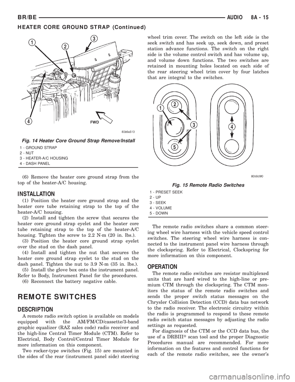
Two rocker-type switches (Fig. 15) are mounted in
the sides of the rear (instrument panel side) steeringwheel trim cover. The switch on the left side is the
seek switch and has seek up, seek down, and preset
station advance functions. The switch on the right
side is the volume control switch and has volume up,
and volume down functions. The two switches are
retained in mounting holes located on each side of
the rear steering wheel trim cover by four latches
that are integral to the switches.
The remote radio switches share a common steer-
ing wheel wire harness with the vehicle speed control
switches. The steering wheel wire harness is con-
nected to the instrument panel wire harness through
the clockspring. Refer to Electrical, Clockspring for
more information on this component.
OPERATION
The remote radio switches are resistor multiplexed
units that are hard wired to the high-line or pre-
mium CTM through the clockspring. The CTM mon-
itors the status of the remote radio switches and
sends the proper switch status messages on the
Chrysler Collision Detection (CCD) data bus network
to the radio receiver. The electronic circuitry within
the radio is programmed to respond to these remote
radio switch status messages by adjusting the radio
settings as requested.
For diagnosis of the CTM or the CCD data bus, the
use of a DRBIIItscan tool and the proper Diagnostic
Procedures manual are recommended. For more
information on the features and control functions for
each of the remote radio switches, see the owner's
Fig. 14 Heater Core Ground Strap Remove/Install
1 - GROUND STRAP
2 - NUT
3 - HEATER-A/C HOUSING
4 - DASH PANEL
Fig. 15 Remote Radio Switches
1 - PRESET SEEK
2-UP
3 - SEEK
4 - VOLUME
5 - DOWN
BR/BEAUDIO 8A - 15
HEATER CORE GROUND STRAP (Continued)
Page 1404 of 2889
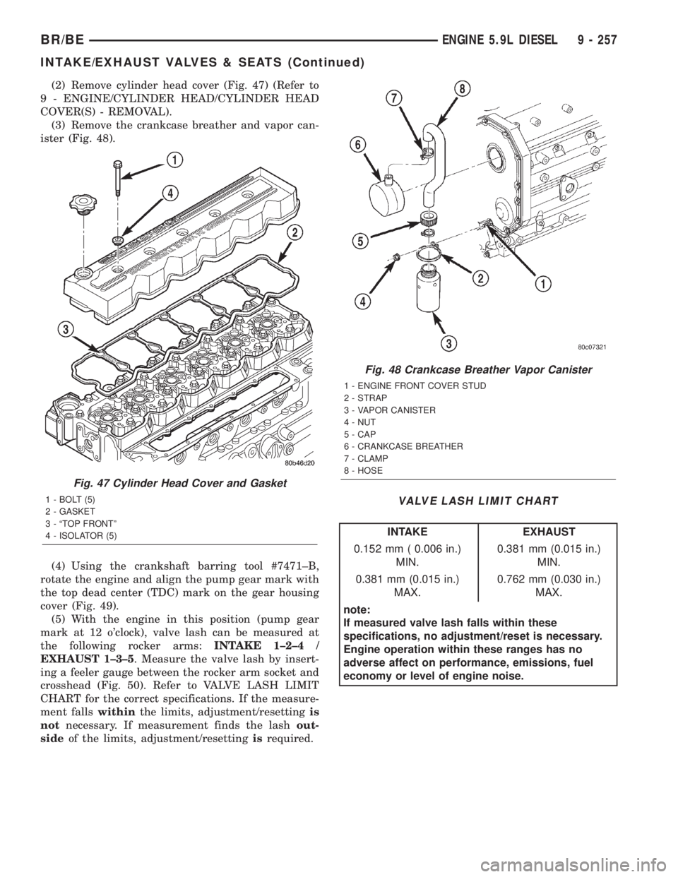
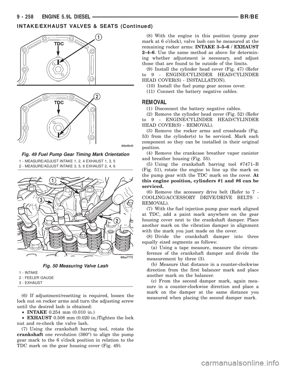
(2) Remove cylinder head cover (Fig. 47) (Refer to
9 - ENGINE/CYLINDER HEAD/CYLINDER HEAD
COVER(S) - REMOVAL).
(3) Remove the crankcase breather and vapor can-
ister (Fig. 48).
(4) Using the crankshaft barring tool #7471±B,
rotate the engine and align the pump gear mark with
the top dead center (TDC) mark on the gear housing
cover (Fig. 49).
(5) With the engine in this position (pump gear
mark at 12 o'clock), valve lash can be measured at
the following rocker arms:INTAKE 1±2±4 /
EXHAUST 1±3±5. Measure the valve lash by insert-
ing a feeler gauge between the rocker arm socket and
crosshead (Fig. 50). Refer to VALVE LASH LIMIT
CHART for the correct specifications. If the measure-
ment fallswithinthe limits, adjustment/resettingis
notnecessary. If measurement finds the lashout-
sideof the limits, adjustment/resettingisrequired.
VALVE LASH LIMIT CHART
INTAKE EXHAUST
0.152 mm ( 0.006 in.)
MIN.0.381 mm (0.015 in.)
MIN.
0.381 mm (0.015 in.)
MAX.0.762 mm (0.030 in.)
MAX.
note:
If measured valve lash falls within these
specifications, no adjustment/reset is necessary.
Engine operation within these ranges has no
adverse affect on performance, emissions, fuel
economy or level of engine noise.
Fig. 47 Cylinder Head Cover and Gasket
1 - BOLT (5)
2 - GASKET
3 - ªTOP FRONTº
4 - ISOLATOR (5)
Fig. 48 Crankcase Breather Vapor Canister
1 - ENGINE FRONT COVER STUD
2 - STRAP
3 - VAPOR CANISTER
4 - NUT
5 - CAP
6 - CRANKCASE BREATHER
7 - CLAMP
8 - HOSE
BR/BEENGINE 5.9L DIESEL 9 - 257
INTAKE/EXHAUST VALVES & SEATS (Continued)
Page 1405 of 2889
(6) If adjustment/resetting is required, loosen the
lock nut on rocker arms and turn the adjusting screw
until the desired lash is obtained:
²INTAKE0.254 mm (0.010 in.)
²EXHAUST0.508 mm (0.020 in.)Tighten the lock
nut and re-check the valve lash.
(7) Using the crankshaft barring tool, rotate the
crankshaftone revolution (360É) to align the pump
gear mark to the 6 o'clock position in relation to the
TDC mark on the gear housing cover (Fig. 49).(8) With the engine in this position (pump gear
mark at 6 o'clock), valve lash can be measured at the
remaining rocker arms:INTAKE 3±5±6 / EXHAUST
2±4±6. Use the same method as above for determin-
ing whether adjustment is necessary, and adjust
those that are found to be outside of the limits.
(9) Install the cylinder head cover (Fig. 47) (Refer
to 9 - ENGINE/CYLINDER HEAD/CYLINDER
HEAD COVER(S) - INSTALLATION).
(10) Install the fuel pump gear access cover.
(11) Connect the battery negative cables.
REMOVAL
(1) Disconnect the battery negative cables.
(2) Remove the cylinder head cover (Fig. 52) (Refer
to 9 - ENGINE/CYLINDER HEAD/CYLINDER
HEAD COVER(S) - REMOVAL).
(3) Remove the rocker arms and crossheads (Fig.
53) from the cylinder(s) to be serviced. Mark each
component so they can be installed in their original
position.
(4) Remove the crankcase breather vapor canister
and breather housing (Fig. 55).
(5) Using the crankshaft barring tool #7471±B
(Fig. 51), rotate the engine to line up the mark on
the pump gear with the TDC mark on the cover.At
this engine position, cylinders #1 and #6 can be
serviced.
(6) Remove the accessory drive belt (Refer to 7 -
COOLING/ACCESSORY DRIVE/DRIVE BELTS -
REMOVAL).
(7) With the fuel injection pump gear mark aligned
at TDC, add a paint mark anywhere on the gear
housing cover next to the crankshaft damper. Place
another mark on the vibration damper in alignment
with the mark you just made on the cover.
(8) Divide the crankshaft damper into three
equally sized segments as follows:
(a) Using a tape measure, measure the circum-
ference of the crankshaft damper and divide the
measurement by three (3).
(b) Measure that distance in a counter-clockwise
direction from the first balancer mark and place
another mark on the balancer.
(c) From the second damper mark, again mea-
sure in a counter-clockwise direction and place a
mark on the damper at the same distance you
measured when placing the second damper mark.
Fig. 49 Fuel Pump Gear Timing Mark Orientation
1 - MEASURE/ADJUST INTAKE 1, 2, 4 EXHAUST 1, 3, 5
2 - MEASURE/ADJUST INTAKE 3, 5, 6 EXHAUST 2, 4, 6
Fig. 50 Measuring Valve Lash
1 - INTAKE
2 - FEELER GAUGE
3 - EXHAUST
9 - 258 ENGINE 5.9L DIESELBR/BE
INTAKE/EXHAUST VALVES & SEATS (Continued)
Page 1939 of 2889
ADJUSTMENTS - VALVE BODY
CONTROL PRESSURE ADJUSTMENTS
There are two control pressure adjustments on the
valve body;
²Line Pressure
²Throttle Pressure
Line and throttle pressures are interdependent
because each affects shift quality and timing. As a
result, both adjustments must be performed properly
and in the correct sequence. Adjust line pressure first
and throttle pressure last.
LINE PRESSURE ADJUSTMENT
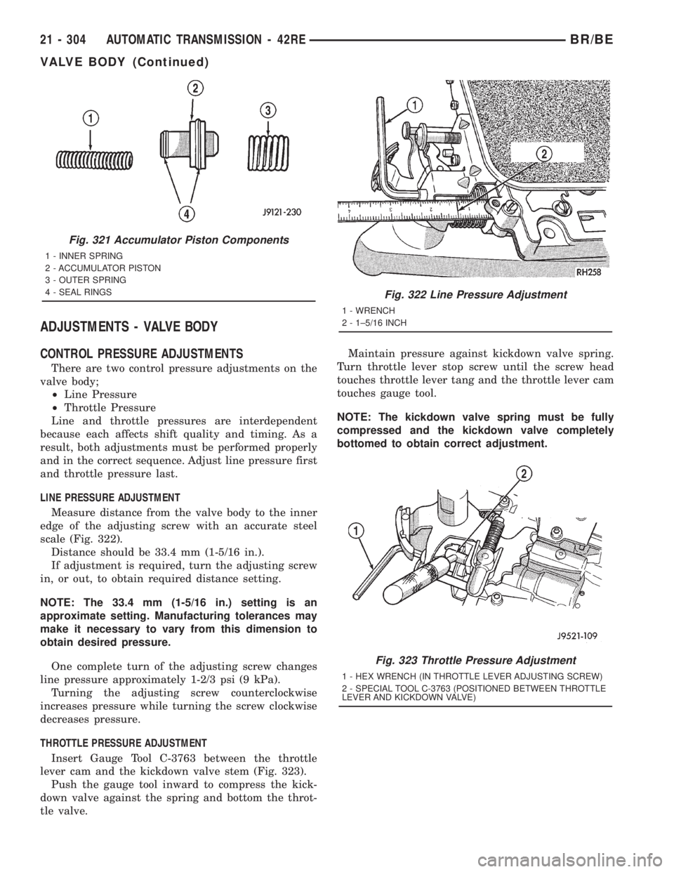
Measure distance from the valve body to the inner
edge of the adjusting screw with an accurate steel
scale (Fig. 322).
Distance should be 33.4 mm (1-5/16 in.).
If adjustment is required, turn the adjusting screw
in, or out, to obtain required distance setting.
NOTE: The 33.4 mm (1-5/16 in.) setting is an
approximate setting. Manufacturing tolerances may
make it necessary to vary from this dimension to
obtain desired pressure.
One complete turn of the adjusting screw changes
line pressure approximately 1-2/3 psi (9 kPa).
Turning the adjusting screw counterclockwise
increases pressure while turning the screw clockwise
decreases pressure.
THROTTLE PRESSURE ADJUSTMENT
Insert Gauge Tool C-3763 between the throttle
lever cam and the kickdown valve stem (Fig. 323).
Push the gauge tool inward to compress the kick-
down valve against the spring and bottom the throt-
tle valve.Maintain pressure against kickdown valve spring.
Turn throttle lever stop screw until the screw head
touches throttle lever tang and the throttle lever cam
touches gauge tool.
NOTE: The kickdown valve spring must be fully
compressed and the kickdown valve completely
bottomed to obtain correct adjustment.
Fig. 321 Accumulator Piston Components
1 - INNER SPRING
2 - ACCUMULATOR PISTON
3 - OUTER SPRING
4 - SEAL RINGS
Fig. 322 Line Pressure Adjustment
1 - WRENCH
2 - 1±5/16 INCH
Fig. 323 Throttle Pressure Adjustment
1 - HEX WRENCH (IN THROTTLE LEVER ADJUSTING SCREW)
2 - SPECIAL TOOL C-3763 (POSITIONED BETWEEN THROTTLE
LEVER AND KICKDOWN VALVE)
21 - 304 AUTOMATIC TRANSMISSION - 42REBR/BE
VALVE BODY (Continued)
Page 2111 of 2889
ADJUSTMENTS - VALVE BODY
CONTROL PRESSURE ADJUSTMENTS
There are two control pressure adjustments on the
valve body;
²Line Pressure
²Throttle Pressure
Line and throttle pressures are interdependent
because each affects shift quality and timing. As a
result, both adjustments must be performed properly
and in the correct sequence. Adjust line pressure first
and throttle pressure last.
LINE PRESSURE ADJUSTMENT
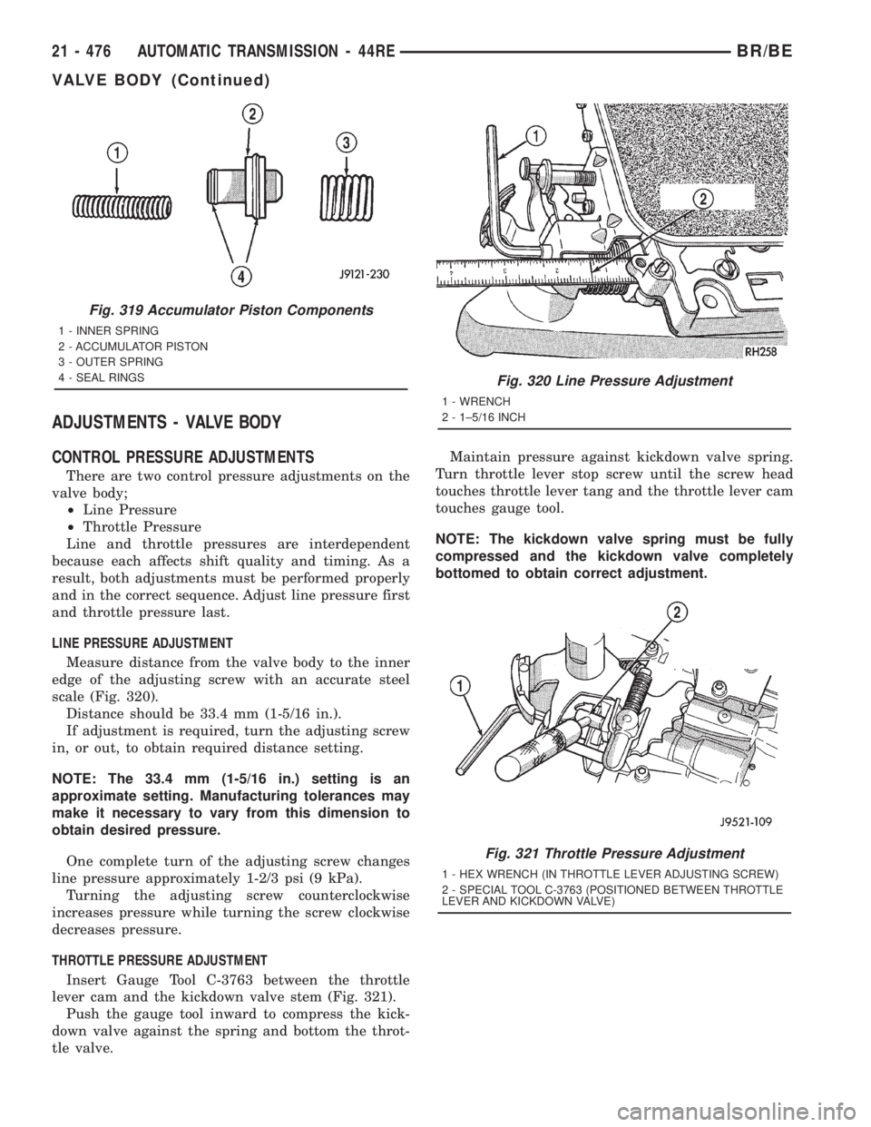
Measure distance from the valve body to the inner
edge of the adjusting screw with an accurate steel
scale (Fig. 320).
Distance should be 33.4 mm (1-5/16 in.).
If adjustment is required, turn the adjusting screw
in, or out, to obtain required distance setting.
NOTE: The 33.4 mm (1-5/16 in.) setting is an
approximate setting. Manufacturing tolerances may
make it necessary to vary from this dimension to
obtain desired pressure.
One complete turn of the adjusting screw changes
line pressure approximately 1-2/3 psi (9 kPa).
Turning the adjusting screw counterclockwise
increases pressure while turning the screw clockwise
decreases pressure.
THROTTLE PRESSURE ADJUSTMENT
Insert Gauge Tool C-3763 between the throttle
lever cam and the kickdown valve stem (Fig. 321).
Push the gauge tool inward to compress the kick-
down valve against the spring and bottom the throt-
tle valve.Maintain pressure against kickdown valve spring.
Turn throttle lever stop screw until the screw head
touches throttle lever tang and the throttle lever cam
touches gauge tool.
NOTE: The kickdown valve spring must be fully
compressed and the kickdown valve completely
bottomed to obtain correct adjustment.
Fig. 319 Accumulator Piston Components
1 - INNER SPRING
2 - ACCUMULATOR PISTON
3 - OUTER SPRING
4 - SEAL RINGS
Fig. 320 Line Pressure Adjustment
1 - WRENCH
2 - 1±5/16 INCH
Fig. 321 Throttle Pressure Adjustment
1 - HEX WRENCH (IN THROTTLE LEVER ADJUSTING SCREW)
2 - SPECIAL TOOL C-3763 (POSITIONED BETWEEN THROTTLE
LEVER AND KICKDOWN VALVE)
21 - 476 AUTOMATIC TRANSMISSION - 44REBR/BE
VALVE BODY (Continued)
Page 2454 of 2889
LINE PRESSURE ADJUSTMENT
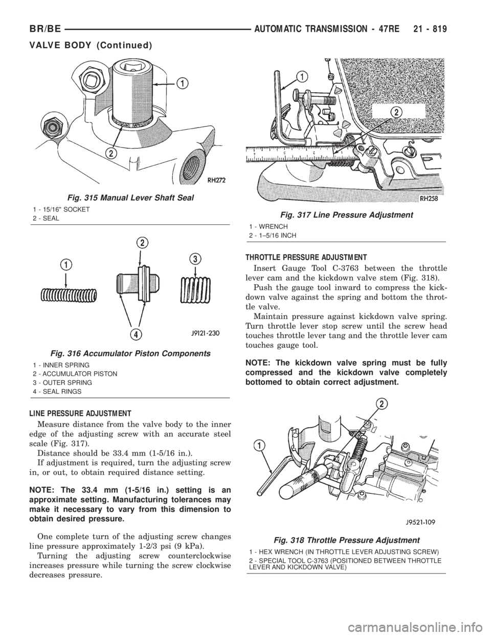
Measure distance from the valve body to the inner
edge of the adjusting screw with an accurate steel
scale (Fig. 317).
Distance should be 33.4 mm (1-5/16 in.).
If adjustment is required, turn the adjusting screw
in, or out, to obtain required distance setting.
NOTE: The 33.4 mm (1-5/16 in.) setting is an
approximate setting. Manufacturing tolerances may
make it necessary to vary from this dimension to
obtain desired pressure.
One complete turn of the adjusting screw changes
line pressure approximately 1-2/3 psi (9 kPa).
Turning the adjusting screw counterclockwise
increases pressure while turning the screw clockwise
decreases pressure.THROTTLE PRESSURE ADJUSTMENT
Insert Gauge Tool C-3763 between the throttle
lever cam and the kickdown valve stem (Fig. 318).
Push the gauge tool inward to compress the kick-
down valve against the spring and bottom the throt-
tle valve.
Maintain pressure against kickdown valve spring.
Turn throttle lever stop screw until the screw head
touches throttle lever tang and the throttle lever cam
touches gauge tool.
NOTE: The kickdown valve spring must be fully
compressed and the kickdown valve completely
bottomed to obtain correct adjustment.
Fig. 315 Manual Lever Shaft Seal
1 - 15/16©© SOCKET
2 - SEAL
Fig. 316 Accumulator Piston Components
1 - INNER SPRING
2 - ACCUMULATOR PISTON
3 - OUTER SPRING
4 - SEAL RINGS
Fig. 317 Line Pressure Adjustment
1 - WRENCH
2 - 1±5/16 INCH
Fig. 318 Throttle Pressure Adjustment
1 - HEX WRENCH (IN THROTTLE LEVER ADJUSTING SCREW)
2 - SPECIAL TOOL C-3763 (POSITIONED BETWEEN THROTTLE
LEVER AND KICKDOWN VALVE)
BR/BEAUTOMATIC TRANSMISSION - 47RE 21 - 819
VALVE BODY (Continued)