low beam DODGE RAM 2001 Service Repair Manual
[x] Cancel search | Manufacturer: DODGE, Model Year: 2001, Model line: RAM, Model: DODGE RAM 2001Pages: 2889, PDF Size: 68.07 MB
Page 7 of 2889
FASTENER USAGE
DESCRIPTION - FASTENER USAGE
WARNING: USE OF AN INCORRECT FASTENER
MAY RESULT IN COMPONENT DAMAGE OR PER-
SONAL INJURY.
Figure art, specifications and torque references in
this Service Manual are identified in metric and SAE
format.
During any maintenance or repair procedures, it is
important to salvage all fasteners (nuts, bolts, etc.)
for reassembly. If the fastener is not salvageable, a
fastener of equivalent specification must be used.
DESCRIPTION - THREADED HOLE REPAIR
Most stripped threaded holes can be repaired using
a Helicoilt. Follow the manufactures recommenda-
tions for application and repair procedures.
INTERNATIONAL VEHICLE
CONTROL & DISPLAY
SYMBOLS
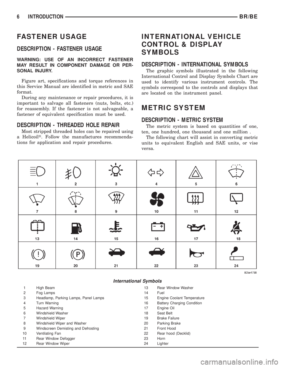
DESCRIPTION - INTERNATIONAL SYMBOLS
The graphic symbols illustrated in the following
International Control and Display Symbols Chart are
used to identify various instrument controls. The
symbols correspond to the controls and displays that
are located on the instrument panel.
METRIC SYSTEM
DESCRIPTION - METRIC SYSTEM
The metric system is based on quantities of one,
ten, one hundred, one thousand and one million .
The following chart will assist in converting metric
units to equivalent English and SAE units, or vise
versa.
International Symbols
1 High Beam 13 Rear Window Washer
2 Fog Lamps 14 Fuel
3 Headlamp, Parking Lamps, Panel Lamps 15 Engine Coolant Temperature
4 Turn Warning 16 Battery Charging Condition
5 Hazard Warning 17 Engine Oil
6 Windshield Washer 18 Seat Belt
7 Windshield Wiper 19 Brake Failure
8 Windshield Wiper and Washer 20 Parking Brake
9 Windscreen Demisting and Defrosting 21 Front Hood
10 Ventilating Fan 22 Rear hood (Decklid)
11 Rear Window Defogger 23 Horn
12 Rear Window Wiper 24 Lighter
6 INTRODUCTIONBR/BE
Page 42 of 2889
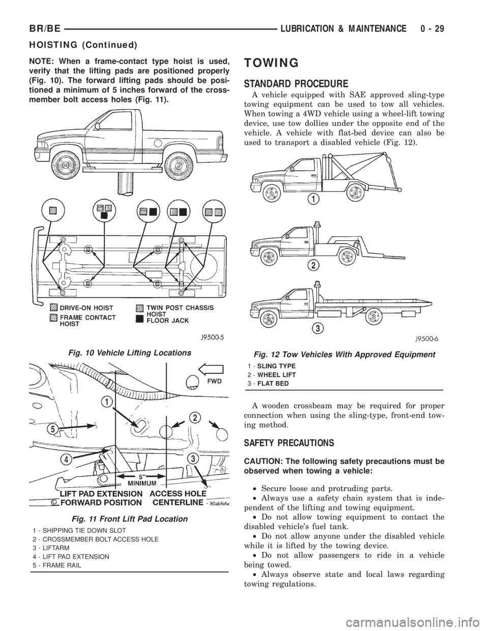
NOTE: When a frame-contact type hoist is used,
verify that the lifting pads are positioned properly
(Fig. 10). The forward lifting pads should be posi-
tioned a minimum of 5 inches forward of the cross-
member bolt access holes (Fig. 11).TOWING
STANDARD PROCEDURE
A vehicle equipped with SAE approved sling-type
towing equipment can be used to tow all vehicles.
When towing a 4WD vehicle using a wheel-lift towing
device, use tow dollies under the opposite end of the
vehicle. A vehicle with flat-bed device can also be
used to transport a disabled vehicle (Fig. 12).
A wooden crossbeam may be required for proper
connection when using the sling-type, front-end tow-
ing method.
SAFETY PRECAUTIONS
CAUTION: The following safety precautions must be
observed when towing a vehicle:
²Secure loose and protruding parts.
²Always use a safety chain system that is inde-
pendent of the lifting and towing equipment.
²Do not allow towing equipment to contact the
disabled vehicle's fuel tank.
²Do not allow anyone under the disabled vehicle
while it is lifted by the towing device.
²Do not allow passengers to ride in a vehicle
being towed.
²Always observe state and local laws regarding
towing regulations.
Fig. 10 Vehicle Lifting Locations
Fig. 11 Front Lift Pad Location
1 - SHIPPING TIE DOWN SLOT
2 - CROSSMEMBER BOLT ACCESS HOLE
3 - LIFTARM
4 - LIFT PAD EXTENSION
5 - FRAME RAIL
Fig. 12 Tow Vehicles With Approved Equipment
1-SLING TYPE
2-WHEEL LIFT
3-FLAT BED
BR/BELUBRICATION & MAINTENANCE 0 - 29
HOISTING (Continued)
Page 85 of 2889
FRONT AXLE - 216FBI
TABLE OF CONTENTS
page page
FRONT AXLE - 216FBI
DESCRIPTION...........................12
OPERATION.............................12
DIAGNOSIS AND TESTING.................13
AXLE................................13
REMOVAL..............................16
INSTALLATION...........................17
ADJUSTMENTS..........................17
SPECIFICATIONS........................25
SPECIAL TOOLS.........................25
AXLE SHAFTS
REMOVAL..............................28
INSTALLATION...........................28
AXLE SHAFTS - INTERMEDIATE
REMOVAL..............................28
INSTALLATION...........................28
AXLE SHAFT SEALS
REMOVAL..............................29
INSTALLATION...........................29
AXLE VACUUM MOTOR
DESCRIPTION...........................29
OPERATION.............................30
DIAGNOSIS AND TESTING.................31VACUUM MOTOR.......................31
REMOVAL..............................33
DISASSEMBLY...........................33
ASSEMBLY.............................33
INSTALLATION...........................33
SINGLE CARDAN UNIVERSAL JOINTS
REMOVAL..............................33
INSTALLATION...........................34
PINION SEAL
REMOVAL..............................34
INSTALLATION...........................34
DIFFERENTIAL
REMOVAL..............................36
DISASSEMBLY...........................36
ASSEMBLY.............................37
INSTALLATION...........................37
DIFFERENTIAL CASE BEARINGS
REMOVAL..............................39
INSTALLATION...........................39
PINION GEAR/RING GEAR
REMOVAL..............................40
INSTALLATION...........................42
FRONT AXLE - 216FBI
DESCRIPTION
The housing for the 216 Front Beam-design Iron
(FBI) axles consists of an iron center casting with
tubes on each side. The tubes are pressed into and
welded to the differential housing.
The integral type housing, hypoid gear design has
the centerline of the pinion set below the centerline
of the ring gear.
The axle has a vent used to relieve internal pres-
sure caused by lubricant vaporization and internal
expansion.
The axles are equipped with semi-floating axle
shafts, meaning that loads are supported by the hub
bearings. The axle shafts are retained by nuts at the
hub bearings. The hub bearings are bolted to the
steering knuckle at the outboard end of the axle tube
yoke. The hub bearings are serviced as an assembly.
The axles are equipped with ABS brake sensors.
The sensors are attached to the knuckle assemblies
and the tone rings are pressed onto the axle shaft.
Use care when removing axle shafts as NOT to
damage the tone wheel or the sensor.The stamped steel cover provides a means for
inspection and servicing the differential.
The 216 axle have the assembly part number and
gear ratio listed on a tag. The tag is attached to the
housing cover by one of the cover bolts. Build date
identification codes are stamped on the cover side of
a axle tube.
The differential case is a one-piece design. The dif-
ferential pinion mate shaft is retained with a roll
pin. Differential bearing preload and ring gear back-
lash is adjusted by the use of shims. The shims are
located between the differential bearing cones and
case. Pinion bearing preload is set and maintained by
the use of a collapsible spacer.
The axle differential covers can be used for identi-
fication of the axle (Fig. 1). A tag is also attached to
the cover.
OPERATION
The axle receives power from the transfer case
through the front propeller shaft. The front propeller
shaft is connected to the pinion gear which rotates
the differential through the gear mesh with the ring
gear bolted to the differential case. The engine power
is transmitted to the axle shafts through the pinion
3 - 12 FRONT AXLE - 216FBIBR/BE
Page 118 of 2889
FRONT AXLE - 248FBI
TABLE OF CONTENTS
page page
FRONT AXLE - 248FBI
DESCRIPTION...........................45
OPERATION.............................45
DIAGNOSIS AND TESTING.................46
AXLE................................46
REMOVAL..............................50
INSTALLATION...........................50
ADJUSTMENTS..........................50
SPECIFICATIONS........................58
SPECIAL TOOLS.........................58
AXLE SHAFTS
REMOVAL..............................60
INSTALLATION...........................60
AXLE SHAFTS - INTERMEDIATE
REMOVAL..............................60
INSTALLATION...........................61
AXLE SHAFT SEALS
REMOVAL..............................61
INSTALLATION...........................61
AXLE VACUUM MOTOR
DESCRIPTION...........................62
OPERATION.............................62
DIAGNOSIS AND TESTING.................63VACUUM MOTOR.......................63
REMOVAL..............................65
DISASSEMBLY...........................65
ASSEMBLY.............................65
INSTALLATION...........................65
SINGLE CARDAN UNIVERSAL JOINTS
REMOVAL..............................65
INSTALLATION...........................66
PINION SEAL
REMOVAL..............................66
INSTALLATION...........................66
DIFFERENTIAL
REMOVAL..............................68
DISASSEMBLY...........................68
ASSEMBLY.............................69
INSTALLATION...........................69
DIFFERENTIAL CASE BEARINGS
REMOVAL..............................71
INSTALLATION...........................71
PINION GEAR/RING GEAR
REMOVAL..............................72
INSTALLATION...........................74
FRONT AXLE - 248FBI
DESCRIPTION
The housing for the 248 Front Beam-design Iron
(FBI) axle consists of an iron center casting with
tubes on each side. The tubes are pressed into and
welded to the differential housing.
The integral type housing, hypoid gear design has
the centerline of the pinion set below the centerline
of the ring gear.
The axle has a vent used to relieve internal pres-
sure caused by lubricant vaporization and internal
expansion.
The axles are equipped with semi-floating axle
shafts, meaning that loads are supported by the hub
bearings. The axle shafts are retained by nuts at the
hub bearings. The hub bearings are bolted to the
steering knuckle at the outboard end of the axle tube
yoke. The hub bearings are serviced as an assembly.
The axles are equipped with ABS brake sensors.
The sensors are attached to the knuckle assemblies
and the tone rings are pressed onto the axle shaft.
Use care when removing axle shafts as NOT to
damage the tone wheel or the sensor.The stamped steel cover provides a means for
inspection and servicing the differential.
The 248 FBI axle have the assembly part number
and gear ratio listed on a tag. The tag is attached to
the housing cover by one of the cover bolts. Build
date identification codes are stamped on the cover
side of a axle tube.
The differential case is a one-piece design. The dif-
ferential pinion mate shaft is retained with a roll
pin. Differential bearing preload and ring gear back-
lash is adjusted by the use of shims. The shims are
located between the differential bearing cones and
case. Pinion bearing preload is set and maintained by
the use of a collapsible spacer.
The axle differential covers can be used for identi-
fication of the axle (Fig. 1). A tag is also attached to
the cover.
OPERATION
The axle receives power from the transfer case
through the front propeller shaft. The front propeller
shaft is connected to the pinion gear which rotates
the differential through the gear mesh with the ring
gear bolted to the differential case. The engine power
is transmitted to the axle shafts through the pinion
BR/BEFRONT AXLE - 248FBI 3 - 45
Page 182 of 2889
REAR AXLE - 248RBI
TABLE OF CONTENTS
page page
REAR AXLE - 248RBI
DESCRIPTION..........................109
OPERATION............................109
DIAGNOSIS AND TESTING.................111
AXLE...............................111
REMOVAL.............................113
INSTALLATION..........................114
ADJUSTMENTS.........................114
SPECIFICATIONS........................122
SPECIAL TOOLS........................122
AXLE SHAFTS
REMOVAL.............................125
INSTALLATION..........................125
AXLE BEARINGS
REMOVAL.............................125
INSTALLATION..........................125
PINION SEAL
REMOVAL.............................125INSTALLATION..........................125
DIFFERENTIAL
REMOVAL.............................127
DISASSEMBLY..........................128
ASSEMBLY............................128
INSTALLATION..........................129
DIFFERENTIAL - TRAC-LOK
DIAGNOSIS AND TESTING................130
TRAC-LOK...........................130
DISASSEMBLY..........................130
ASSEMBLY............................132
DIFFERENTIAL CASE BEARINGS
REMOVAL.............................134
INSTALLATION..........................134
PINION GEAR/RING GEAR/TONE RING
REMOVAL.............................135
INSTALLATION..........................137
REAR AXLE - 248RBI
DESCRIPTION
The Rear Beam-design Iron (RBI) axle housings
consist of an iron center casting (differential housing)
with axle shaft tubes extending from either side. The
tubes are pressed in to form a one-piece axle housing.
The integral type housing, hypoid gear design has
the centerline of the pinion set below the centerline
of the ring gear.
The axles are equipped with full-floating axle
shafts, meaning that loads are supported by the axle
housing tubes. The full-float axle shafts are retained
by bolts attached to the hub. The hub rides on two
bearings at the outboard end of the axle tube. The
axle shafts can be removed without disturbing or
removing the wheel bearings. The wheel bearings are
opposed tapered roller bearings and are contained in
the hub assembly.
The removable, stamped steel cover provides a
means for inspection and service without removing
the complete axle from the vehicle. A small, stamped
metal axle gear ratio identification tag is attached to
the housing cover via one of the cover bolts. This tag
also identifies the number of ring and pinion teeth.
The rear wheel anti-lock (RWAL) brake speed sen-
sor is attached to the top, forward exterior of the dif-
ferential housing. A seal is located between the
sensor and the wire harness connector. The seal mustbe in place when the wire connector is connected to
the sensor. The RWAL brake exciter ring is press-fit-
ted onto the differential case against the ring gear
flange.
The differential case for the standard differentials
and the Trac-lokydifferential are a one-piece design.
The differential pinion mate shaft is retained with a
roll pin. Differential bearing preload and ring gear
backlash are adjusted by the use of shims located
between the differential bearing cones and case. Pin-
ion bearing preload is set and maintained by the use
of a solid shims.
OPERATION
STANDARD DIFFERENTIAL
The axle receives power from the transmission/
transfer case through the rear propeller shaft. The
rear propeller shaft is connected to the pinion gear
which rotates the differential through the gear mesh
with the ring gear bolted to the differential case. The
engine power is transmitted to the axle shafts
through the pinion mate and side gears. The side
gears are splined to the axle shafts.
During straight-ahead driving, the differential pin-
ion gears do not rotate on the pinion mate shaft. This
occurs because input torque applied to the gears is
divided and distributed equally between the two side
BR/BEREAR AXLE - 248RBI 3 - 109
Page 213 of 2889
REAR AXLE - 267RBI
TABLE OF CONTENTS
page page
REAR AXLE - 267RBI
DESCRIPTION..........................140
OPERATION............................140
DIAGNOSIS AND TESTING................142
AXLE...............................142
REMOVAL.............................144
INSTALLATION..........................145
ADJUSTMENTS.........................145
SPECIFICATIONS........................153
SPECIAL TOOLS........................153
AXLE SHAFTS
REMOVAL.............................156
INSTALLATION..........................156
AXLE BEARINGS
REMOVAL.............................156
INSTALLATION..........................156
PINION SEAL
REMOVAL.............................156INSTALLATION..........................157
DIFFERENTIAL
REMOVAL.............................158
DISASSEMBLY..........................158
ASSEMBLY............................159
INSTALLATION..........................159
DIFFERENTIAL - POWR-LOK
DIAGNOSIS AND TESTING................161
POWR-LOK .........................161
DISASSEMBLY..........................161
ASSEMBLY............................163
DIFFERENTIAL CASE BEARINGS
REMOVAL.............................164
INSTALLATION..........................164
PINION GEAR/RING GEAR/TONE RING
REMOVAL.............................165
INSTALLATION..........................166
REAR AXLE - 267RBI
DESCRIPTION
The Rear Beam-design Iron (RBI) axle housings
consist of an iron center casting (differential housing)
with axle shaft tubes extending from either side. The
tubes are pressed in to form a one-piece axle housing.
The integral type housing, hypoid gear design has
the centerline of the pinion set below the centerline
of the ring gear.
The axles are equipped with full-floating axle
shafts, meaning that loads are supported by the axle
housing tubes. The full-float axle shafts are retained
by bolts attached to the hub. The hub rides on two
bearings at the outboard end of the axle tube. The
axle shafts can be removed without disturbing or
removing the wheel bearings. The wheel bearings are
opposed tapered roller bearings and are contained in
the hub assembly.
The removable, stamped steel cover provides a
means for inspection and service without removing
the complete axle from the vehicle. A small, stamped
metal axle gear ratio identification tag is attached to
the housing cover via one of the cover bolts. This tag
also identifies the number of ring and pinion teeth.
The rear wheel anti-lock (RWAL) brake speed sen-
sor is attached to the top, forward exterior of the dif-
ferential housing. A seal is located between the
sensor and the wire harness connector. The seal mustbe in place when the wire connector is connected to
the sensor. The RWAL brake exciter ring is press-fit-
ted onto the differential case against the ring gear
flange.
The differential case for the standard differential is
a one-piece design. The differential pinion mate shaft
is retained with a roll pin. Differential bearing pre-
load and ring gear backlash are adjusted by the use
of shims located between the differential bearing
cones and case. Pinion bearing preload is set and
maintained by the use of a solid shims.
Axles equipped with a Powr-Lokydifferential are
optional. A Powr-lokydifferential has a two-piece dif-
ferential case. A Powr-lokydifferential contains four
pinion gears and a two-piece pinion mate cross shaft
to provide increased torque to the non-slipping wheel
through a ramping motion in addition to the stan-
dard Trac-lokycomponents.
OPERATION
STANDARD DIFFERENTIAL
The axle receives power from the transmission/
transfer case through the rear propeller shaft. The
rear propeller shaft is connected to the pinion gear
which rotates the differential through the gear mesh
with the ring gear bolted to the differential case. The
engine power is transmitted to the axle shafts
3 - 140 REAR AXLE - 267RBIBR/BE
Page 242 of 2889
REAR AXLE - 286RBI
TABLE OF CONTENTS
page page
REAR AXLE - 286RBI
DESCRIPTION..........................169
OPERATION............................169
DIAGNOSIS AND TESTING................171
AXLE...............................171
REMOVAL.............................173
INSTALLATION..........................174
ADJUSTMENTS.........................174
SPECIFICATIONS........................182
SPECIAL TOOLS........................182
AXLE SHAFTS
REMOVAL.............................185
INSTALLATION..........................185
AXLE BEARINGS
REMOVAL.............................185
INSTALLATION..........................185
PINION SEAL
REMOVAL.............................185INSTALLATION..........................185
DIFFERENTIAL
REMOVAL.............................187
DISASSEMBLY..........................188
ASSEMBLY............................188
INSTALLATION..........................188
DIFFERENTIAL - TRAC-LOK
DIAGNOSIS AND TESTING................190
TRAC-LOK...........................190
DISASSEMBLY..........................190
ASSEMBLY............................190
DIFFERENTIAL CASE BEARINGS
REMOVAL.............................192
INSTALLATION..........................192
PINION GEAR/RING GEAR/TONE RING
REMOVAL.............................193
INSTALLATION..........................195
REAR AXLE - 286RBI
DESCRIPTION
The 286 Rear Beam-design Iron (RBI) axle hous-
ings consist of an iron center casting (differential
housing) with axle shaft tubes extending from either
side. The tubes are pressed in to form a one-piece
axle housing.
The integral type housing, hypoid gear design has
the centerline of the pinion set below the centerline
of the ring gear.
The axles are equipped with full-floating axle
shafts, meaning that loads are supported by the axle
housing tubes. The full-float axle shafts are retained
by bolts attached to the hub. The hub rides on two
bearings at the outboard end of the axle tube. The
axle shafts can be removed without disturbing or
removing the wheel bearings. The wheel bearings are
opposed tapered roller bearings and are contained in
the hub assembly.
The removable, stamped steel cover provides a
means for inspection and service without removing
the complete axle from the vehicle. A small, stamped
metal axle gear ratio identification tag is attached to
the housing cover via one of the cover bolts. This tag
also identifies the number of ring and pinion teeth.
The rear wheel anti-lock (RWAL) brake speed sen-
sor is attached to the top, forward exterior of the dif-
ferential housing. A seal is located between thesensor and the wire harness connector. The seal must
be in place when the wire connector is connected to
the sensor. The RWAL brake exciter ring is press-fit-
ted onto the differential case against the ring gear
flange.
The differential case for the standard differential is
a one-piece design. The differential pinion mate shaft
is retained with a roll pin. Differential bearing pre-
load and ring gear backlash are adjusted by the use
of shims located between the differential bearing
cones and case. Pinion bearing preload is set and
maintained by the use of solid shims.
Axles equipped with a Trac-Lokydifferential are
optional for the 286 RBI axle. A Trac-lokydifferen-
tial contains two clutch packs, four pinion gears, and
a one-piece pinion mate cross shaft to provide
increased torque to the non-slipping wheel in addi-
tion to the standard differential components. A Trac-
lokydifferential for the 286 RBI axle has a two-piece
differential case.
OPERATION
STANDARD DIFFERENTIAL
The axle receives power from the transmission/
transfer case through the rear propeller shaft. The
rear propeller shaft is connected to the pinion gear
which rotates the differential through the gear mesh
with the ring gear bolted to the differential case. The
engine power is transmitted to the axle shafts
BR/BEREAR AXLE - 286RBI 3 - 169
Page 560 of 2889
INSTRUMENT CLUSTER
TABLE OF CONTENTS
page page
INSTRUMENT CLUSTER
DESCRIPTION............................2
OPERATION.............................3
DIAGNOSIS AND TESTING..................6
INSTRUMENT CLUSTER..................6
REMOVAL..............................10
DISASSEMBLY...........................11
ASSEMBLY.............................13
INSTALLATION...........................14
ABS INDICATOR
DESCRIPTION...........................14
OPERATION.............................14
AIRBAG INDICATOR
DESCRIPTION...........................15
OPERATION.............................15
BRAKE/PARK BRAKE INDICATOR
DESCRIPTION...........................16
OPERATION.............................16
DIAGNOSIS AND TESTING.................16
BRAKE INDICATOR.....................16
CHECK GAUGES INDICATOR
DESCRIPTION...........................17
OPERATION.............................17
CRUISE INDICATOR
DESCRIPTION...........................18
OPERATION.............................18
ENGINE TEMPERATURE GAUGE
DESCRIPTION...........................19
OPERATION.............................19
FUEL GAUGE
DESCRIPTION...........................20
OPERATION.............................20
GEAR SELECTOR INDICATOR
DESCRIPTION...........................21
OPERATION.............................21
HIGH BEAM INDICATOR
DESCRIPTION...........................21
OPERATION.............................22
DIAGNOSIS AND TESTING.................22
HIGH BEAM INDICATOR.................22
LOW FUEL INDICATOR
DESCRIPTION...........................23
OPERATION.............................23
MALFUNCTION INDICATOR LAMP (MIL)
DESCRIPTION...........................24
OPERATION.............................24
ODOMETER
DESCRIPTION...........................24
OPERATION.............................25OIL PRESSURE GAUGE
DESCRIPTION...........................25
OPERATION.............................26
OVERDRIVE OFF INDICATOR
DESCRIPTION...........................27
OPERATION.............................27
SEATBELT INDICATOR
DESCRIPTION...........................27
OPERATION.............................27
SERVICE REMINDER INDICATOR
DESCRIPTION...........................28
OPERATION.............................28
SHIFT INDICATOR (TRANSFER CASE)
DESCRIPTION...........................29
OPERATION.............................29
DIAGNOSIS AND TESTING.................29
FOUR-WHEEL DRIVE INDICATOR..........29
SPEEDOMETER
DESCRIPTION...........................30
OPERATION.............................30
TACHOMETER
DESCRIPTION...........................30
OPERATION.............................31
TRANSMISSION OVERTEMP INDICATOR
DESCRIPTION...........................31
OPERATION.............................31
TURN SIGNAL INDICATORS
DESCRIPTION...........................32
OPERATION.............................32
DIAGNOSIS AND TESTING.................32
TURN SIGNAL INDICATORS..............32
UPSHIFT INDICATOR
DESCRIPTION...........................33
OPERATION.............................33
VOLTAGE GAUGE
DESCRIPTION...........................33
OPERATION.............................34
WAIT-TO-START INDICATOR
DESCRIPTION...........................34
OPERATION.............................35
WASHER FLUID INDICATOR
DESCRIPTION...........................35
OPERATION.............................35
DIAGNOSIS AND TESTING.................36
WASHER FLUID INDICATOR..............36
WATER-IN-FUEL INDICATOR
DESCRIPTION...........................36
OPERATION.............................37
BR/BEINSTRUMENT CLUSTER 8J - 1
Page 562 of 2889
²Check Gauges Indicator
²Cruise Indicator (Odometer VFD)
²Four-Wheel Drive Indicator
²High Beam Indicator
²Low Fuel Indicator
²Washer Fluid Indicator
²Malfunction Indicator Lamp (MIL)
²Overdrive-Off Indicator
²Seatbelt Indicator
²Service Reminder Indicator (SRI)
²Transmission Overtemp Indicator
²Turn Signal (Right and Left) Indicators
²Upshift Indicator
²Wait-To-Start Indicator (Diesel Only)
²Water-In-Fuel Indicator (Diesel Only)
Some of these indicators are either programmable
or automatically configured when the EMIC is con-
nected to the vehicle electrical system. This feature
allows those indicators to be activated or deactivated
for compatibility with certain optional equipment.
The EMIC also includes a provision for mounting the
automatic transmission gear selector indicator in the
lower right corner of the cluster. The spring-loaded,
cable driven, mechanical gear selector indicator gives
an indication of the transmission gear that has been
selected with the automatic transmission gear selec-
tor lever. The gear selector indicator pointer is easily
visible through an opening provided in the front of
the cluster overlay, and is also lighted by the cluster
illumination lamps for visibility at night. Models
equipped with a manual transmission have a block-
out plate installed in place of the gear selector indi-
cator.
Cluster illumination is accomplished by adjustable
incandescent back lighting, which illuminates the
gauges for visibility when the exterior lighting is
turned on. The EMIC high beam indicator, turn sig-
nal indicators, and wait-to-start indicator are also
illuminated by dedicated incandescent bulbs. The
remaining indicators in the EMIC are each illumi-
nated by a dedicated Light Emitting Diode (LED)
that is soldered onto the electronic circuit board.
Each of the incandescent bulbs is secured by an inte-
gral bulb holder to the electronic circuit board from
the back of the cluster housing.
Hard wired circuitry connects the EMIC to the
electrical system of the vehicle. These hard wired cir-
cuits are integral to several wire harnesses, which
are routed throughout the vehicle and retained by
many different methods. These circuits may be con-
nected to each other, to the vehicle electrical system
and to the EMIC through the use of a combination of
soldered splices, splice block connectors, and many
different types of wire harness terminal connectors
and insulators. Refer to the appropriate wiring infor-
mation. The wiring information includes wiring dia-grams, proper wire and connector repair procedures,
further details on wire harness routing and reten-
tion, as well as pin-out and location views for the
various wire harness connectors, splices and grounds.
The EMIC modules for this model are serviced only
as complete units. The EMIC module cannot be
adjusted or repaired. If a gauge, an LED indicator,
the VFD, the electronic circuit board, the circuit
board hardware, the cluster overlay, or the EMIC
housing are damaged or faulty, the entire EMIC mod-
ule must be replaced. The cluster lens and hood unit,
the rear cluster housing cover, the automatic trans-
mission gear selector indicator, and the incandescent
lamp bulbs with holders are available for individual
service replacement.
OPERATION
The ElectroMechanical Instrument Cluster (EMIC)
is designed to allow the vehicle operator to monitor
the conditions of many of the vehicle components and
operating systems. The gauges and indicators in the
EMIC provide valuable information about the various
standard and optional powertrains, fuel and emis-
sions systems, cooling systems, lighting systems,
safety systems and many other convenience items.
The EMIC is installed in the instrument panel so
that all of these monitors can be easily viewed by the
vehicle operator when driving, while still allowing
relative ease of access for service. The microproces-
sor-based EMIC hardware and software uses various
inputs to control the gauges and indicators visible on
the face of the cluster. Some of these inputs are hard
wired, but most are in the form of electronic mes-
sages that are transmitted by other electronic mod-
ules over the Chrysler Collision Detection (CCD) data
bus network. (Refer to 8 - ELECTRICAL/ELEC-
TRONIC CONTROL MODULES/COMMUNICATION
- OPERATION).
The EMIC microprocessor smooths the input data
using algorithms to provide gauge readings that are
accurate, stable and responsive to operating condi-
tions. These algorithms are designed to provide
gauge readings during normal operation that are con-
sistent with customer expectations. However, when
abnormal conditions exist, such as low/high battery
voltage, low oil pressure, or high coolant tempera-
ture, the algorithm drives the gauge pointer to an
extreme position and the microprocessor turns on the
Check Gauges indicator to provide a distinct visual
indication of a problem to the vehicle operator. The
instrument cluster circuitry may also generate a
hard wired chime tone request to the Central Timer
Module (CTM) when it monitors certain conditions or
inputs, in order to provide the vehicle operator with
an audible alert.
BR/BEINSTRUMENT CLUSTER 8J - 3
INSTRUMENT CLUSTER (Continued)
Page 564 of 2889
The VFD is diagnosed using the EMIC self-diag-
nostic actuator test. (Refer to 8 - ELECTRICAL/IN-
STRUMENT CLUSTER - DIAGNOSIS AND
TESTING). Proper testing of the CCD data bus and
the data bus message inputs to the EMIC that con-
trol some of the VFD functions requires the use of a
DRBIIItscan tool. Refer to the appropriate diagnos-
tic information. Specific operation details for the
odometer and trip odometer functions of the VFD
may be found elsewhere in this service manual.
INDICATORS
Indicators are located in various positions within
the EMIC and are all connected to the EMIC circuit
board. The four-wheel drive indicator, high beam
indicator, washer fluid indicator, turn signal indica-
tors, and wait-to-start indicator are hard wired. The
brake indicator is controlled by CCD data bus mes-
sages from the Controller Anti-lock Brake (CAB) and
the hard wired park brake switch input to the EMIC.
The seatbelt indicator is controlled by the EMIC pro-
gramming, CCD data bus messages from the Airbag
Control Module (ACM), and the hard wired seat belt
switch input to the EMIC. The Malfunction Indicator
Lamp (MIL) is normally controlled by CCD data bus
messages from the Powertrain Control Module
(PCM); however, if the EMIC loses CCD data bus
communications, the EMIC circuitry will automati-
cally turn the MIL on, and flash the odometer VFD
on and off repeatedly until CCD data bus communi-
cation is restored. The EMIC uses CCD data bus
messages from the Powertrain Control Module
(PCM), the diesel engine only Engine Control Module
(ECM), the ACM, and the CAB to control all of the
remaining indicators. Different indicators are con-
trolled by different strategies; some receive fused
ignition switch output from the EMIC circuitry clus-
ter and have a switched ground, while others are
grounded through the EMIC circuitry and have a
switched battery feed.
In addition, certain indicators in this instrument
cluster are programmable or configurable. This fea-
ture allows the programmable indicators to be acti-
vated or deactivated with a DRBIIItscan tool, while
the configurable indicators will be automatically
enabled or disabled by the EMIC circuitry for com-
patibility with certain optional equipment. The only
programmable indicator for this model is the upshift
indicator. The cruise indicator, four-wheel drive indi-
cator, overdrive-off indicator, service reminder indica-
tor, and the transmission overtemp indicator are
automatically configured, either electronically or
mechanically.The hard wired indicators are diagnosed using con-
ventional diagnostic methods. The EMIC and CCD
bus message controlled indicator lamps are diagnosed
using the EMIC self-diagnostic actuator test. (Refer
to 8 - ELECTRICAL/INSTRUMENT CLUSTER -
DIAGNOSIS AND TESTING). Proper testing of the
CCD data bus and the data bus message inputs to
the EMIC that control each indicator lamp require
the use of a DRBIIItscan tool. Refer to the appro-
priate diagnostic information. Specific operation
details for each indicator may be found elsewhere in
this service manual.
CLUSTER ILLUMINATION
The EMIC has several illumination lamps that are
illuminated when the exterior lighting is turned on
with the headlamp switch. The illumination bright-
ness of these lamps is adjusted by the panel lamps
dimmer rheostat when the headlamp switch thumb-
wheel is rotated (down to dim, up to brighten). The
illumination lamps receive battery current through
the panel lamps dimmer rheostat and a fuse in the
JB on a fused panel lamps dimmer switch signal cir-
cuit. The illumination lamps are grounded at all
times.
In addition, an analog/digital (A/D) converter in
the EMIC converts the analog panel lamps dimmer
rheostat input from the headlamp switch to a digital
dimming level signal for controlling the lighting level
of the VFD. The EMIC also broadcasts this digital
dimming information as a message over the CCD
data bus for use by the Compass Mini-Trip Computer
(CMTC) in synchronizing the lighting level of its
VFD with that of the EMIC. The headlamp switch
thumbwheel also has a Parade position to provide a
parade mode. The EMIC monitors the request for
this mode through a hard wired day brightness sense
circuit input from the headlamp switch. In this mode,
the EMIC will override the selected panel dimmer
switch signal and send a message over the CCD data
bus to illuminate all vacuum fluorescent displays at
full brightness for easier visibility when driving in
daylight with the exterior lighting turned on. The
parade mode has no effect on the incandescent bulb
illumination intensity.
The hard wired cluster illumination lamps are
diagnosed using conventional diagnostic methods.
Proper testing of the VFD dimming level and the
CCD data bus dimming level message functions
requires the use of a DRBIIItscan tool. Refer to the
appropriate diagnostic information.
BR/BEINSTRUMENT CLUSTER 8J - 5
INSTRUMENT CLUSTER (Continued)