shock DODGE RAM 2001 Service Repair Manual
[x] Cancel search | Manufacturer: DODGE, Model Year: 2001, Model line: RAM, Model: DODGE RAM 2001Pages: 2889, PDF Size: 68.07 MB
Page 50 of 2889
FRONT - 2WD
TABLE OF CONTENTS
page page
FRONT - 2WD
DESCRIPTION............................7
SPECIFICATIONS.........................8
SPECIAL TOOLS..........................9
HUB / BEARING
REMOVAL...............................9
INSTALLATION............................9
JOUNCE BUMPER
DESCRIPTION............................9
OPERATION.............................9
KNUCKLE
DESCRIPTION............................9
OPERATION.............................10
REMOVAL..............................10
INSTALLATION...........................10
LOWER BALL JOINT
DIAGNOSIS AND TESTING.................10
LOWER BALL JOINT....................10
LOWER CONTROL ARM
REMOVAL..............................10
INSTALLATION...........................10
SHOCK
DESCRIPTION...........................11OPERATION.............................11
DIAGNOSIS AND TESTING.................11
SHOCK...............................11
REMOVAL..............................11
INSTALLATION...........................11
SPRING
DESCRIPTION...........................11
OPERATION.............................11
REMOVAL..............................11
INSTALLATION...........................12
STABILIZER BAR
DESCRIPTION...........................12
OPERATION.............................12
REMOVAL..............................12
INSTALLATION...........................12
UPPER BALL JOINT
DIAGNOSIS AND TESTING.................12
UPPER BALL JOINT.....................12
UPPER CONTROL ARM
REMOVAL..............................13
INSTALLATION...........................13
FRONT - 2WD
DESCRIPTION
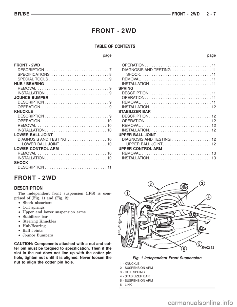
The independent front suspension (IFS) is com-
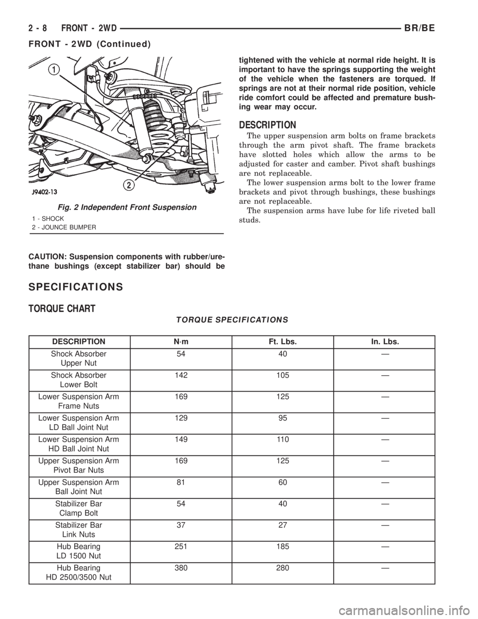
prised of (Fig. 1) and (Fig. 2):
²Shock absorbers
²Coil springs
²Upper and lower suspension arms
²Stabilizer bar
²Steering Knuckles
²Hub/Bearing
²Ball Joints
²Jounce Bumpers
CAUTION: Components attached with a nut and cot-
ter pin must be torqued to specification. Then if the
slot in the nut does not line up with the cotter pin
hole, tighten nut until it is aligned. Never loosen the
nut to align the cotter pin hole.
Fig. 1 Independent Front Suspension
1 - KNUCKLE
2 - SUSPENSION ARM
3 - COIL SPRING
4 - STABILIZER BAR
5 - SUSPENSION ARM
6 - LINK
BR/BEFRONT - 2WD 2 - 7
Page 51 of 2889
CAUTION: Suspension components with rubber/ure-
thane bushings (except stabilizer bar) should betightened with the vehicle at normal ride height. It is
important to have the springs supporting the weight
of the vehicle when the fasteners are torqued. If
springs are not at their normal ride position, vehicle
ride comfort could be affected and premature bush-
ing wear may occur.
DESCRIPTION
The upper suspension arm bolts on frame brackets
through the arm pivot shaft. The frame brackets
have slotted holes which allow the arms to be
adjusted for caster and camber. Pivot shaft bushings
are not replaceable.
The lower suspension arms bolt to the lower frame
brackets and pivot through bushings, these bushings
are not replaceable.
The suspension arms have lube for life riveted ball
studs.
SPECIFICATIONS
TORQUE CHART
TORQUE SPECIFICATIONS
DESCRIPTION N´m Ft. Lbs. In. Lbs.
Shock Absorber
Upper Nut54 40 Ð
Shock Absorber
Lower Bolt142 105 Ð
Lower Suspension Arm
Frame Nuts169 125 Ð
Lower Suspension Arm
LD Ball Joint Nut129 95 Ð
Lower Suspension Arm
HD Ball Joint Nut149 110 Ð
Upper Suspension Arm
Pivot Bar Nuts169 125 Ð
Upper Suspension Arm
Ball Joint Nut81 60 Ð
Stabilizer Bar
Clamp Bolt54 40 Ð
Stabilizer Bar
Link Nuts37 27 Ð
Hub Bearing
LD 1500 Nut251 185 Ð
Hub Bearing
HD 2500/3500 Nut380 280 Ð
Fig. 2 Independent Front Suspension
1 - SHOCK
2 - JOUNCE BUMPER
2 - 8 FRONT - 2WDBR/BE
FRONT - 2WD (Continued)
Page 53 of 2889
OPERATION
The steering knuckles pivots between the upper
and lower ball joints. The steering linkage is
attached to the knuckles controls vehicle steering.
REMOVAL
(1) Raise and support the vehicle.
(2) Remove the wheel and tire assembly.
(3) Remove the brake caliper and rotor, (Refer to 5
- BRAKES/HYDRAULIC/MECHANICAL/DISC
BRAKE CALIPERS - REMOVAL).
(4) Remove the cotter pin and nut from the tie-rod
end. Remove the tie rod end from the knuckle with
Puller C-3894-A.
(5) Remove the cotter pins and nuts from the
upper and lower ball joints. Separate upper ball joint
from knuckle with remover MD-990635. Separate
lower ball joint with remover C-4150A and remove
knuckle.
INSTALLATION
(1) Position the knuckle on the ball joints and
install the ball joint nuts.
(2) Tighten the upper ball joint nut to 81 N´m (60
ft. lbs.) and install cotter pin.
(3) Tighten the lower ball joint nut to:
²LD: 129 N´m (95 ft. lbs.)
²HD: 149 N´m (110 ft. lbs.)
(3) Install the cotter pin.
(4) Install the tie rod end on the steering knuckle
and tighten the nut to 108 N´m (80 ft. lbs.). Install
cotter pin.
(5) Install the brake rotor and caliper, (Refer to 5 -
BRAKES/HYDRAULIC/MECHANICAL/DISC
BRAKE CALIPERS - INSTALLATION).
(6) Install wheel and tire assembly (Refer to 22 -
TIRES/WHEELS/WHEELS - STANDARD PROCE-
DURE).
(7) Remove support and lower vehicle.
LOWER BALL JOINT
DIAGNOSIS AND TESTING - LOWER BALL
JOINT
(1) Raise the front of the vehicle. Place safety floor
stands under both lower suspension arms as far out-
board as possible. Lower the vehicle to allow the
stands to support some or all of the vehicle weight.
NOTE: The upper suspension arms must not be in
maximum rebound position.
(2) Remove the tire and wheel assembly.
(3) Mount a dial indicator solidly under the lower
suspension arm.(4) Position indicator plunger against the bottom
of the steering knuckle lower ball joint boss.
NOTE: The dial Indicator plunger must be perpen-
dicular to the machined surface of the steering
knuckle lower ball joint boss.
(5) Position a pry bar over the top of the upper
suspension arm and under the pivot bar of the upper
suspension arm. Pry down on the upper suspension
arm and then zero the dial indicator.
(6) Reposition the pry bar under the upper suspen-
sion arm and on top of the frame rail. Pry up on the
upper suspension arm and record the dial indicator
reading.
(7) If the travel exceeds 0.8 mm (0.030 in.) replace
the suspension arm.
LOWER CONTROL ARM
REMOVAL
(1) Raise and support the vehicle.
(2) Remove the tire and wheel assembly.
(3) Remove the brake caliper assembly and rotor,
(Refer to 5 - BRAKES/HYDRAULIC/MECHANICAL/
ROTORS - REMOVAL).
(4) Remove the cotter pin and nut from the tie rod.
Remove the tie rod end from the steering knuckle
with Puller C-3894-A.
(5) Remove the stabilizer bar link from lower sus-
pension arm.
(6) Support the lower suspension arm outboard
end with jack. Place a jack under the arm in the
front of the shock mount.
(7) Remove the cotter pin and nut from the lower
ball joint. Separate the ball joint with Remover
C-4150A.
(8) Remove the lower shock bolt from the suspen-
sion arm.
(9) Lower the jack and suspension arm until
spring tension is relieved. Remove spring and rubber
isolator (Fig. 5).
(10) Remove bolts mounting suspension arm to
crossmember and remove arm.
INSTALLATION
(1) Position the suspension arm on the crossmem-
ber and install the bolts and nuts snug.
(2) Install the rubber isolator on top of the spring.
Position the spring into upper spring seat.
(3) Raise the lower suspension arm with a jack
and position the spring into the lower suspension
arm mount.
(4) Install the lower shock bolt and tighten to 142
N´m (105 ft. lbs.).
2 - 10 FRONT - 2WDBR/BE
KNUCKLE (Continued)
Page 54 of 2889
(5) Install the steering knuckle on the lower ball
joint. Install the lower ball joint nut and tighten to:
²LD: 129 N´m (95 ft. lbs.)
²HD: 136 N´m (110 ft. lbs.)
(5) Install the lower ball joint cotter pin.
(6) Install the stabilizer bar link on the lower sus-
pension arm. Install the grommet, retainer and nut
and tighten to 37 N´m (27 ft. lbs.).
(7) Install the tie rod end on the steering knuckle
and tighten nut to 108 N´m (80 ft. lbs.). Install cotter
pin.
(8) Install the brake rotor and caliper assembly,
(Refer to 5 - BRAKES/HYDRAULIC/MECHANICAL/
ROTORS - INSTALLATION).
(9) Install the tire and wheel assembly, (Refer to
22 - TIRES/WHEELS/WHEELS - STANDARD PRO-
CEDURE).
(10) Remove the support and lower the vehicle.
(11) Tighten the suspension arm crossmember
nuts to 169 N´m (125 ft. lbs.).
SHOCK
DESCRIPTION
The top of the shocks mounts on frame brackets
using grommets. The bottom of the shock is bolted to
the lower suspension arms.
OPERATION
The shock absorbers dampen jounce and rebound
of the vehicle over various road conditions.
DIAGNOSIS AND TESTING - SHOCK
A knocking or rattling noise from a shock absorber
may be caused by movement between mounting
bushings and metal brackets or attaching compo-
nents. These noises can usually be stopped by tight-
ening the attaching nuts. If the noise persists,
inspect for damaged and worn bushings, and attach-
ing components. Repair as necessary if any of these
conditions exist.
A squeaking noise from the shock absorber may be
caused by the hydraulic valving and may be intermit-
tent. This condition is not repairable and the shock
absorber must be replaced.
The shock absorbers are not refillable or adjust-
able. If a malfunction occurs, the shock absorber
must be replaced. To test a shock absorber, hold it in
an upright position and force the piston in and out of
the cylinder four or five times. The action throughout
each stroke should be smooth and even.
The shock absorber bushings do not require any
type of lubrication. Do not attempt to stop bushing
noise by lubricating them. Grease and mineral oil-
base lubricants will deteriorate the bushing.
REMOVAL
(1) Raise and support vehicle.
(2) Remove shock upper nut and remove retainer
and grommet.
(3) Remove lower mounting bolt from suspension
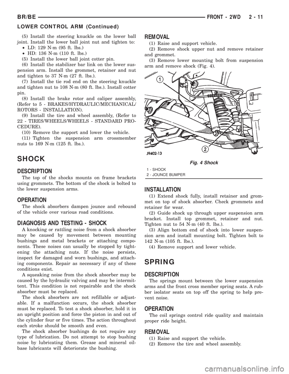
arm and remove shock (Fig. 4).
INSTALLATION
(1) Extend shock fully, install retainer and grom-
met on top of shock absorber. Check grommets and
retainer for wear.
(2) Guide shock up through upper suspension arm
bracket. Install top grommet, retainer and nut.
Tighten nut to 54 N´m (40 ft. lbs.).
(3) Align bottom end of shock into lower suspen-
sion arm and install mounting bolt. Tighten bolt to
142 N´m (105 ft. lbs.).
(4) Remove support and lower vehicle.
SPRING
DESCRIPTION
The springs mount between the lower suspension
arms and the front cross member spring seats. A rub-
ber isolator seats on top off the spring to help pre-
vent noise.
OPERATION
The coil springs control ride quality and maintain
proper ride height.
REMOVAL
(1) Raise and support the vehicle.
(2) Remove the tire and wheel assembly.
Fig. 4 Shock
1 - SHOCK
2 - JOUNCE BUMPER
BR/BEFRONT - 2WD 2 - 11
LOWER CONTROL ARM (Continued)
Page 55 of 2889
(3) Remove the brake caliper assembly and rotor,
(Refer to 5 - BRAKES/HYDRAULIC/MECHANICAL/
ROTORS - REMOVAL).
(4) Remove the cotter pin and nut from the tie rod.
Remove the tie rod end from the steering knuckle
with Puller C-3894-A.
(5) Remove the stabilizer bar link from the lower
suspension arm.
(6) Support the lower suspension arm outboard
end with a jack. Place a jack under the arm in front
of the shock mount.
(7) Remove the cotter pin and nut from the lower
ball joint. Separate the ball joint with Remover
C-4150A.
(8) Remove the lower shock bolt from the suspen-
sion arm.
(9) Lower the jack and suspension arm until
spring tension is relieved. Remove spring and rubber
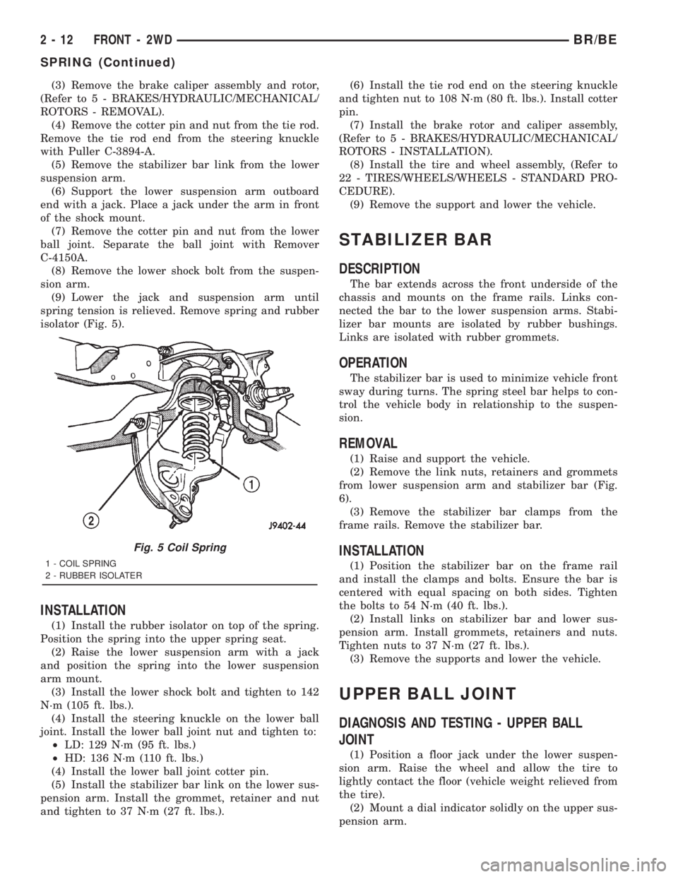
isolator (Fig. 5).
INSTALLATION
(1) Install the rubber isolator on top of the spring.
Position the spring into the upper spring seat.
(2) Raise the lower suspension arm with a jack
and position the spring into the lower suspension
arm mount.
(3) Install the lower shock bolt and tighten to 142
N´m (105 ft. lbs.).
(4) Install the steering knuckle on the lower ball
joint. Install the lower ball joint nut and tighten to:
²LD: 129 N´m (95 ft. lbs.)
²HD: 136 N´m (110 ft. lbs.)
(4) Install the lower ball joint cotter pin.
(5) Install the stabilizer bar link on the lower sus-
pension arm. Install the grommet, retainer and nut
and tighten to 37 N´m (27 ft. lbs.).(6) Install the tie rod end on the steering knuckle
and tighten nut to 108 N´m (80 ft. lbs.). Install cotter
pin.
(7) Install the brake rotor and caliper assembly,
(Refer to 5 - BRAKES/HYDRAULIC/MECHANICAL/
ROTORS - INSTALLATION).
(8) Install the tire and wheel assembly, (Refer to
22 - TIRES/WHEELS/WHEELS - STANDARD PRO-
CEDURE).
(9) Remove the support and lower the vehicle.
STABILIZER BAR
DESCRIPTION
The bar extends across the front underside of the
chassis and mounts on the frame rails. Links con-
nected the bar to the lower suspension arms. Stabi-
lizer bar mounts are isolated by rubber bushings.
Links are isolated with rubber grommets.
OPERATION
The stabilizer bar is used to minimize vehicle front
sway during turns. The spring steel bar helps to con-
trol the vehicle body in relationship to the suspen-
sion.
REMOVAL
(1) Raise and support the vehicle.
(2) Remove the link nuts, retainers and grommets
from lower suspension arm and stabilizer bar (Fig.
6).
(3) Remove the stabilizer bar clamps from the
frame rails. Remove the stabilizer bar.
INSTALLATION
(1) Position the stabilizer bar on the frame rail
and install the clamps and bolts. Ensure the bar is
centered with equal spacing on both sides. Tighten
the bolts to 54 N´m (40 ft. lbs.).
(2) Install links on stabilizer bar and lower sus-
pension arm. Install grommets, retainers and nuts.
Tighten nuts to 37 N´m (27 ft. lbs.).
(3) Remove the supports and lower the vehicle.
UPPER BALL JOINT
DIAGNOSIS AND TESTING - UPPER BALL
JOINT
(1) Position a floor jack under the lower suspen-
sion arm. Raise the wheel and allow the tire to
lightly contact the floor (vehicle weight relieved from
the tire).
(2) Mount a dial indicator solidly on the upper sus-
pension arm.
Fig. 5 Coil Spring
1 - COIL SPRING
2 - RUBBER ISOLATER
2 - 12 FRONT - 2WDBR/BE
SPRING (Continued)
Page 57 of 2889
FRONT - 4WD
TABLE OF CONTENTS
page page
FRONT - 4WD
DESCRIPTION...........................14
SPECIFICATIONS........................15
SPECIAL TOOLS.........................16
HUB / BEARING
REMOVAL..............................16
INSTALLATION...........................18
KNUCKLE
DESCRIPTION...........................20
OPERATION.............................20
REMOVAL..............................20
INSTALLATION...........................20
LOWER CONTROL ARM
REMOVAL..............................20
INSTALLATION...........................20
SHOCK
DESCRIPTION...........................21
OPERATION.............................21
DIAGNOSIS AND TESTING.................21
SHOCK..............................21
REMOVAL..............................21
INSTALLATION...........................21
SPRING
DESCRIPTION...........................22OPERATION.............................22
REMOVAL..............................22
INSTALLATION...........................22
STABILIZER BAR
DESCRIPTION...........................22
OPERATION.............................22
REMOVAL..............................22
INSTALLATION...........................23
TRACK BAR
DESCRIPTION...........................23
OPERATION.............................23
DIAGNOSIS AND TESTING.................23
TRACK BAR...........................23
REMOVAL..............................23
INSTALLATION...........................23
UPPER CONTROL ARM
REMOVAL..............................23
INSTALLATION...........................24
LOWER BALL JOINT
REMOVAL..............................24
INSTALLATION...........................25
UPPER BALL JOINT
REMOVAL..............................25
INSTALLATION...........................25
FRONT - 4WD
DESCRIPTION
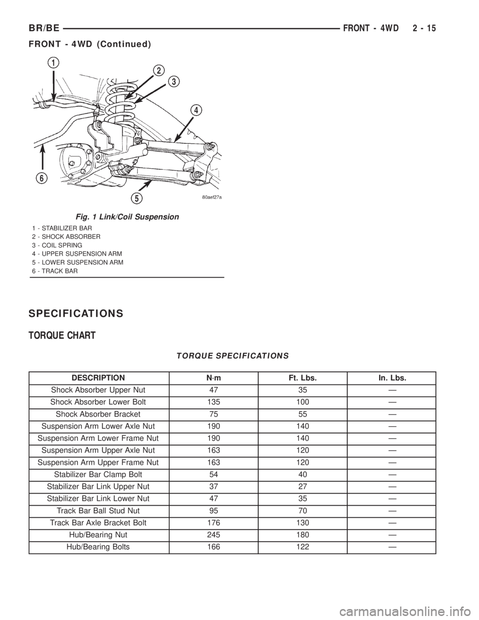
The link/coil suspension allows each wheel to adapt
to different road surfaces. The suspension is com-
prised of (Fig. 1) :
²Shock absorbers
²Coil springs
²Upper and lower suspension arms
²Stabilizer bar
²Track bar
²Steering Knuckles
²Hub/Bearing
²Ball Joints
²Jounce Bumpers
CAUTION: Components attached with a nut and cot-
ter pin must be torqued to specification. Then if the
slot in the nut does not line up with the cotter pin
hole, tighten nut until it is aligned. Never loosen the
nut to align the cotter pin hole.CAUTION: Suspension components with rubber
bushings (except stabilizer bar) should be tightened
with the vehicle at normal height. It is important to
have the springs supporting the weight of the vehi-
cle when the fasteners are torqued. If springs are
not at their normal ride position, vehicle ride com-
fort could be affected and premature bushing wear
may occur.
DESCRIPTION
The upper and lower suspension arms use bush-
ings to isolate road noise. The suspension arms are
bolted to the frame and axle through the rubber
bushings. The lower suspension arm uses cam bolts
at the axle to allow for caster and pinion angle
adjustment.
2 - 14 FRONT - 4WDBR/BE
Page 58 of 2889
SPECIFICATIONS
TORQUE CHART
TORQUE SPECIFICATIONS
DESCRIPTION N´m Ft. Lbs. In. Lbs.
Shock Absorber Upper Nut 47 35 Ð
Shock Absorber Lower Bolt 135 100 Ð
Shock Absorber Bracket 75 55 Ð
Suspension Arm Lower Axle Nut 190 140 Ð
Suspension Arm Lower Frame Nut 190 140 Ð
Suspension Arm Upper Axle Nut 163 120 Ð
Suspension Arm Upper Frame Nut 163 120 Ð
Stabilizer Bar Clamp Bolt 54 40 Ð
Stabilizer Bar Link Upper Nut 37 27 Ð
Stabilizer Bar Link Lower Nut 47 35 Ð
Track Bar Ball Stud Nut 95 70 Ð
Track Bar Axle Bracket Bolt 176 130 Ð
Hub/Bearing Nut 245 180 Ð
Hub/Bearing Bolts 166 122 Ð
Fig. 1 Link/Coil Suspension
1 - STABILIZER BAR
2 - SHOCK ABSORBER
3 - COIL SPRING
4 - UPPER SUSPENSION ARM
5 - LOWER SUSPENSION ARM
6 - TRACK BAR
BR/BEFRONT - 4WD 2 - 15
FRONT - 4WD (Continued)
Page 64 of 2889
SHOCK
DESCRIPTION
The shocks are mounted inside the springs and
attached at the top to brackets with grommets. These
brackets are bolted on the frame with three studs on
a ring. The shock is mounted at the bottom of the
axle below the spring seat.
OPERATION
The shock absorbers dampen the jounce and
rebound of the vehicle over various road conditions.
DIAGNOSIS AND TESTING - SHOCK
A knocking or rattling noise from a shock absorber
may be caused by movement between mounting
bushings and metal brackets or attaching compo-
nents. These noises can usually be stopped by tight-
ening the attaching nuts. If the noise persists,
inspect for damaged and worn bushings, and attach-
ing components. Repair as necessary if any of these
conditions exist.
A squeaking noise from the shock absorber may be
caused by the hydraulic valving and may be intermit-
tent. This condition is not repairable and the shock
absorber must be replaced.
The shock absorbers are not refillable or adjust-
able. If a malfunction occurs, the shock absorbermust be replaced. To test a shock absorber, hold it in
an upright position and force the piston in and out of
the cylinder four or five times. The action throughout
each stroke should be smooth and even.
The shock absorber bushings do not require any
type of lubrication. Do not attempt to stop bushing
noise by lubricating them. Grease and mineral oil-
base lubricants will deteriorate the bushing.
REMOVAL
(1) Remove the nut, retainer and grommet from
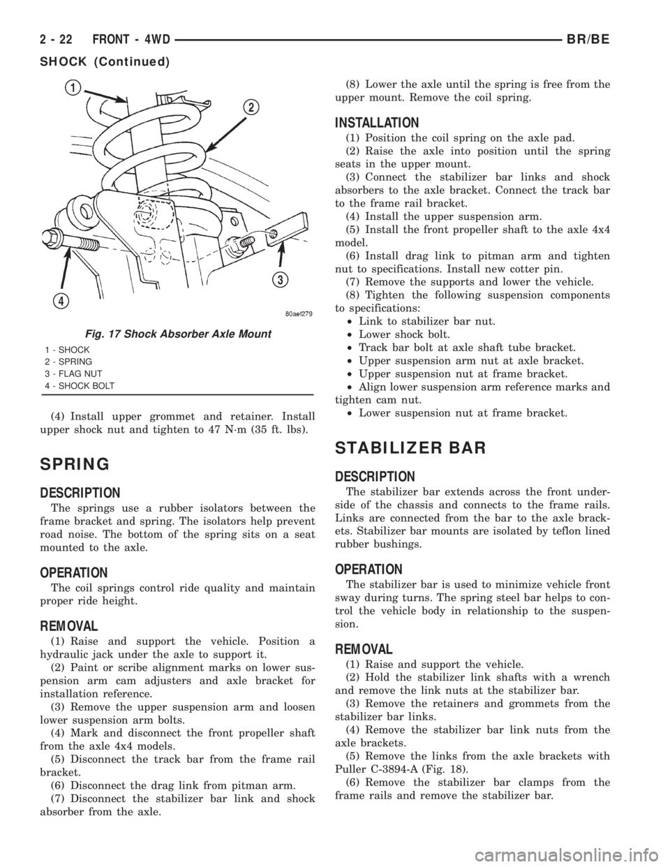
the upper stud in the engine compartment.
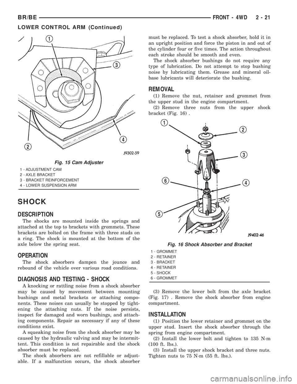
(2) Remove three nuts from the upper shock
bracket (Fig. 16) .
(3) Remove the lower bolt from the axle bracket
(Fig. 17) . Remove the shock absorber from engine
compartment.
INSTALLATION
(1) Position the lower retainer and grommet on the
upper stud. Insert the shock absorber through the
spring from engine compartment.
(2) Install the lower bolt and tighten to 135 N´m
(100 ft. lbs.).
(3) Install the upper shock bracket and three nuts.
Tighten nuts to 75 N´m (55 ft. lbs.).
Fig. 15 Cam Adjuster
1 - ADJUSTMENT CAM
2 - AXLE BRACKET
3 - BRACKET REINFORCEMENT
4 - LOWER SUSPENSION ARM
Fig. 16 Shock Absorber and Bracket
1 - GROMMET
2 - RETAINER
3 - BRACKET
4 - RETAINER
5 - SHOCK
6 - GROMMET
BR/BEFRONT - 4WD 2 - 21
LOWER CONTROL ARM (Continued)
Page 65 of 2889
(4) Install upper grommet and retainer. Install
upper shock nut and tighten to 47 N´m (35 ft. lbs).
SPRING
DESCRIPTION
The springs use a rubber isolators between the
frame bracket and spring. The isolators help prevent
road noise. The bottom of the spring sits on a seat
mounted to the axle.
OPERATION
The coil springs control ride quality and maintain
proper ride height.
REMOVAL
(1) Raise and support the vehicle. Position a
hydraulic jack under the axle to support it.
(2) Paint or scribe alignment marks on lower sus-
pension arm cam adjusters and axle bracket for
installation reference.
(3) Remove the upper suspension arm and loosen
lower suspension arm bolts.
(4) Mark and disconnect the front propeller shaft
from the axle 4x4 models.
(5) Disconnect the track bar from the frame rail
bracket.
(6) Disconnect the drag link from pitman arm.
(7) Disconnect the stabilizer bar link and shock
absorber from the axle.(8) Lower the axle until the spring is free from the
upper mount. Remove the coil spring.
INSTALLATION
(1) Position the coil spring on the axle pad.
(2) Raise the axle into position until the spring
seats in the upper mount.
(3) Connect the stabilizer bar links and shock
absorbers to the axle bracket. Connect the track bar
to the frame rail bracket.
(4) Install the upper suspension arm.
(5) Install the front propeller shaft to the axle 4x4
model.
(6) Install drag link to pitman arm and tighten
nut to specifications. Install new cotter pin.
(7) Remove the supports and lower the vehicle.
(8) Tighten the following suspension components
to specifications:
²Link to stabilizer bar nut.
²Lower shock bolt.
²Track bar bolt at axle shaft tube bracket.
²Upper suspension arm nut at axle bracket.
²Upper suspension nut at frame bracket.
²Align lower suspension arm reference marks and
tighten cam nut.
²Lower suspension nut at frame bracket.
STABILIZER BAR
DESCRIPTION
The stabilizer bar extends across the front under-
side of the chassis and connects to the frame rails.
Links are connected from the bar to the axle brack-
ets. Stabilizer bar mounts are isolated by teflon lined
rubber bushings.
OPERATION
The stabilizer bar is used to minimize vehicle front
sway during turns. The spring steel bar helps to con-
trol the vehicle body in relationship to the suspen-
sion.
REMOVAL
(1) Raise and support the vehicle.
(2) Hold the stabilizer link shafts with a wrench
and remove the link nuts at the stabilizer bar.
(3) Remove the retainers and grommets from the
stabilizer bar links.
(4) Remove the stabilizer bar link nuts from the
axle brackets.
(5) Remove the links from the axle brackets with
Puller C-3894-A (Fig. 18).
(6) Remove the stabilizer bar clamps from the
frame rails and remove the stabilizer bar.
Fig. 17 Shock Absorber Axle Mount
1 - SHOCK
2 - SPRING
3 - FLAG NUT
4 - SHOCK BOLT
2 - 22 FRONT - 4WDBR/BE
SHOCK (Continued)
Page 67 of 2889
(3) Remove the nut and bolt at the frame rail and
remove the upper suspension arm.
INSTALLATION
(1) Position the upper suspension arm at the axle
and frame rail.
(2) Install the bolts and finger tighten the nuts.
(3) Remove the supports and lower the vehicle.
(4) Tighten nut at the axle bracket to 163 N´m
(120 ft. lbs.). Tighten nut at frame bracket to 163
N´m (120 ft. lbs.).
LOWER BALL JOINT
REMOVAL -
(1) Remove lower snap ring from the lower ball
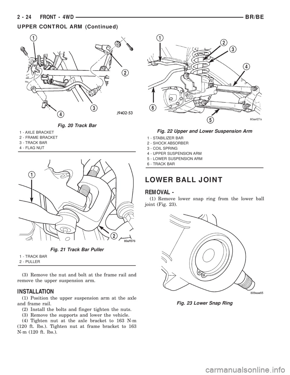
joint (Fig. 23).
Fig. 20 Track Bar
1 - AXLE BRACKET
2 - FRAME BRACKET
3 - TRACK BAR
4 - FLAG NUT
Fig. 21 Track Bar Puller
1 - TRACK BAR
2 - PULLER
Fig. 22 Upper and Lower Suspension Arm
1 - STABILIZER BAR
2 - SHOCK ABSORBER
3 - COIL SPRING
4 - UPPER SUSPENSION ARM
5 - LOWER SUSPENSION ARM
6 - TRACK BAR
Fig. 23 Lower Snap Ring
2 - 24 FRONT - 4WDBR/BE
UPPER CONTROL ARM (Continued)