weight DODGE RAM 2001 Service Repair Manual
[x] Cancel search | Manufacturer: DODGE, Model Year: 2001, Model line: RAM, Model: DODGE RAM 2001Pages: 2889, PDF Size: 68.07 MB
Page 12 of 2889
tification Number. The check digit is used by the
manufacturer and government agencies to verify the
authenticity of the vehicle and official documenta-
tion. The formula to use the check digit is not
released to the general public.
POSITION INTERPRETATION CODE = DESCRIPTION
1 Country of Origin 1 = United States
3 = Mexico
2 Make B = Dodge
3 Vehicle Type 6 = Incomplete
7 = Truck
4 Gross Vehicle Weight Rating H = 6001-7000
J = 7001-8000
K = 8001-9000
L = 9001-10,000
M = 10,001-14,000
5 Vehicle Line C = Ram Cab Chassis/Ram Pick Up (4x2)
F = Ram Cab Chassis/Ram Pick Up (4x4)
6 Series 1 = 1500
2 = 2500
3 = 3500
7 Body Style 2 = Club Cab
3 = Quad Cab
6 = Conventional Cab/Cab Chassis
8 Engine 6 = 5.9L 6 cyl. 24 Valve Diesel
7=5.9 6cyl. 24 Valve Turbo Diesel H/O
W = 8.0L 10 cyl. MPI
X = 3.9L 6 cyl. MPI
Y = 5.2L 8 cyl. MPI
Z = 5.9L 8 cyl. MPI-LDC
5 = 5.9L 8cyl. MPI-HDC
9 Check Digit 0 through 9 or X
10 Model Year 1=2001
11 Plant Location J = St. Louis North
S = Dodge City
M = Lago Alberto Assembly
12 thru 17 Vehicle Build Sequence
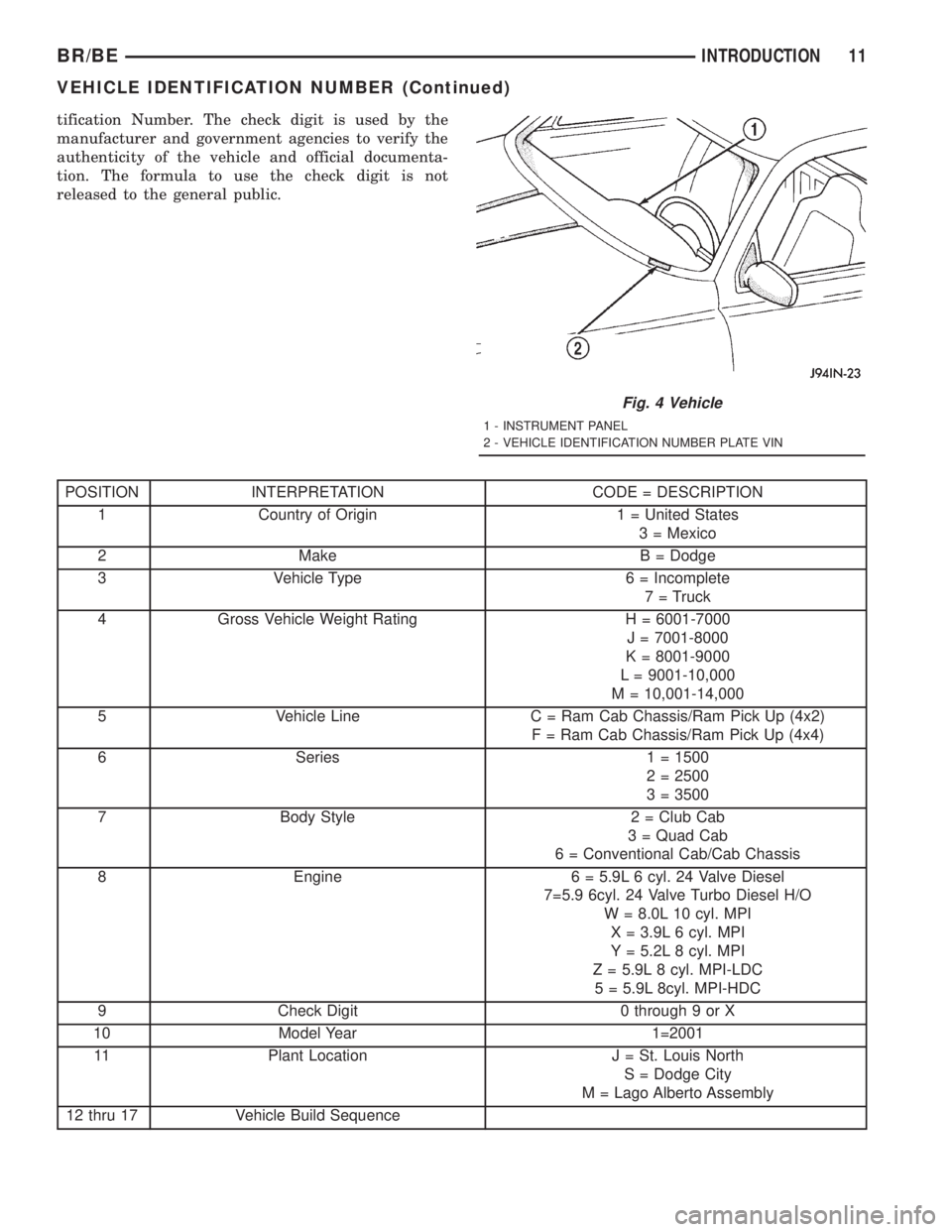
Fig. 4 Vehicle
1 - INSTRUMENT PANEL
2 - VEHICLE IDENTIFICATION NUMBER PLATE VIN
BR/BEINTRODUCTION 11
VEHICLE IDENTIFICATION NUMBER (Continued)
Page 13 of 2889
VEHICLE SAFETY
CERTIFICATION LABEL
DESCRIPTION
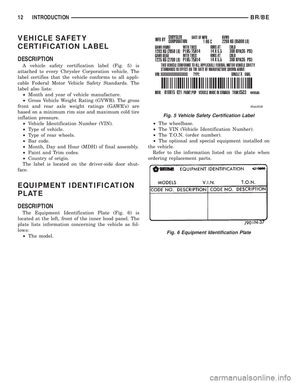
A vehicle safety certification label (Fig. 5) is
attached to every Chrysler Corporation vehicle. The
label certifies that the vehicle conforms to all appli-
cable Federal Motor Vehicle Safety Standards. The
label also lists:
²Month and year of vehicle manufacture.
²Gross Vehicle Weight Rating (GVWR). The gross
front and rear axle weight ratings (GAWR's) are
based on a minimum rim size and maximum cold tire
inflation pressure.
²Vehicle Identification Number (VIN).
²Type of vehicle.
²Type of rear wheels.
²Bar code.
²Month, Day and Hour (MDH) of final assembly.
²Paint and Trim codes.
²Country of origin.
The label is located on the driver-side door shut-
face.
EQUIPMENT IDENTIFICATION
PLATE
DESCRIPTION
The Equipment Identification Plate (Fig. 6) is
located at the left, front of the inner hood panel. The
plate lists information concerning the vehicle as fol-
lows:
²The model.²The wheelbase.
²The VIN (Vehicle Identification Number).
²The T.O.N. (order number).
²The optional and special equipment installed on
the vehicle.
Refer to the information listed on the plate when
ordering replacement parts.
Fig. 5 Vehicle Safety Certification Label
Fig. 6 Equipment Identification Plate
12 INTRODUCTIONBR/BE
Page 49 of 2889
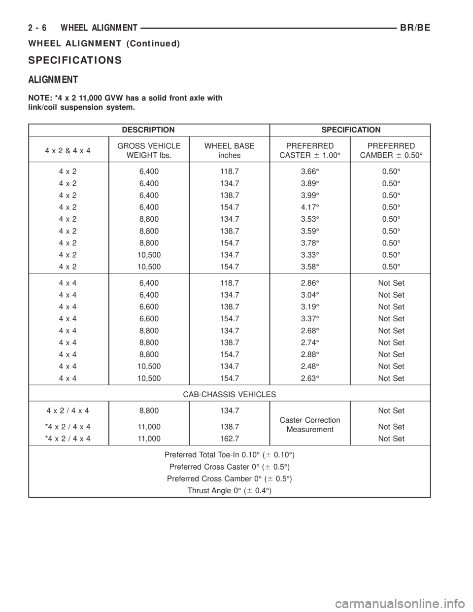
SPECIFICATIONS
ALIGNMENT
NOTE: *4x211,000 GVW has a solid front axle with
link/coil suspension system.
DESCRIPTION SPECIFICATION
4x2&4x4GROSS VEHICLE
WEIGHT lbs.WHEEL BASE
inchesPREFERRED
CASTER61.00ÉPREFERRED
CAMBER60.50É
4 x 2 6,400 118.7 3.66É 0.50É
4 x 2 6,400 134.7 3.89É 0.50É
4 x 2 6,400 138.7 3.99É 0.50É
4 x 2 6,400 154.7 4.17É 0.50É
4 x 2 8,800 134.7 3.53É 0.50É
4 x 2 8,800 138.7 3.59É 0.50É
4 x 2 8,800 154.7 3.78É 0.50É
4 x 2 10,500 134.7 3.33É 0.50É
4 x 2 10,500 154.7 3.58É 0.50É
4 x 4 6,400 118.7 2.86É Not Set
4 x 4 6,400 134.7 3.04É Not Set
4 x 4 6,600 138.7 3.19É Not Set
4 x 4 6,600 154.7 3.37É Not Set
4 x 4 8,800 134.7 2.68É Not Set
4 x 4 8,800 138.7 2.74É Not Set
4 x 4 8,800 154.7 2.88É Not Set
4 x 4 10,500 134.7 2.48É Not Set
4 x 4 10,500 154.7 2.63É Not Set
CAB-CHASSIS VEHICLES
4x2/4x48,800 134.7
Caster Correction
MeasurementNot Set
*4x2/4x4 11,000 138.7 Not Set
*4x2/4x4 11,000 162.7 Not Set
Preferred Total Toe-In 0.10É (60.10É)
Preferred Cross Caster 0É (60.5É)
Preferred Cross Camber 0É (60.5É)
Thrust Angle 0É (60.4É)
2 - 6 WHEEL ALIGNMENTBR/BE
WHEEL ALIGNMENT (Continued)
Page 51 of 2889
CAUTION: Suspension components with rubber/ure-
thane bushings (except stabilizer bar) should betightened with the vehicle at normal ride height. It is
important to have the springs supporting the weight
of the vehicle when the fasteners are torqued. If
springs are not at their normal ride position, vehicle
ride comfort could be affected and premature bush-
ing wear may occur.
DESCRIPTION
The upper suspension arm bolts on frame brackets
through the arm pivot shaft. The frame brackets
have slotted holes which allow the arms to be
adjusted for caster and camber. Pivot shaft bushings
are not replaceable.
The lower suspension arms bolt to the lower frame
brackets and pivot through bushings, these bushings
are not replaceable.
The suspension arms have lube for life riveted ball
studs.
SPECIFICATIONS
TORQUE CHART
TORQUE SPECIFICATIONS
DESCRIPTION N´m Ft. Lbs. In. Lbs.
Shock Absorber
Upper Nut54 40 Ð
Shock Absorber
Lower Bolt142 105 Ð
Lower Suspension Arm
Frame Nuts169 125 Ð
Lower Suspension Arm
LD Ball Joint Nut129 95 Ð
Lower Suspension Arm
HD Ball Joint Nut149 110 Ð
Upper Suspension Arm
Pivot Bar Nuts169 125 Ð
Upper Suspension Arm
Ball Joint Nut81 60 Ð
Stabilizer Bar
Clamp Bolt54 40 Ð
Stabilizer Bar
Link Nuts37 27 Ð
Hub Bearing
LD 1500 Nut251 185 Ð
Hub Bearing
HD 2500/3500 Nut380 280 Ð
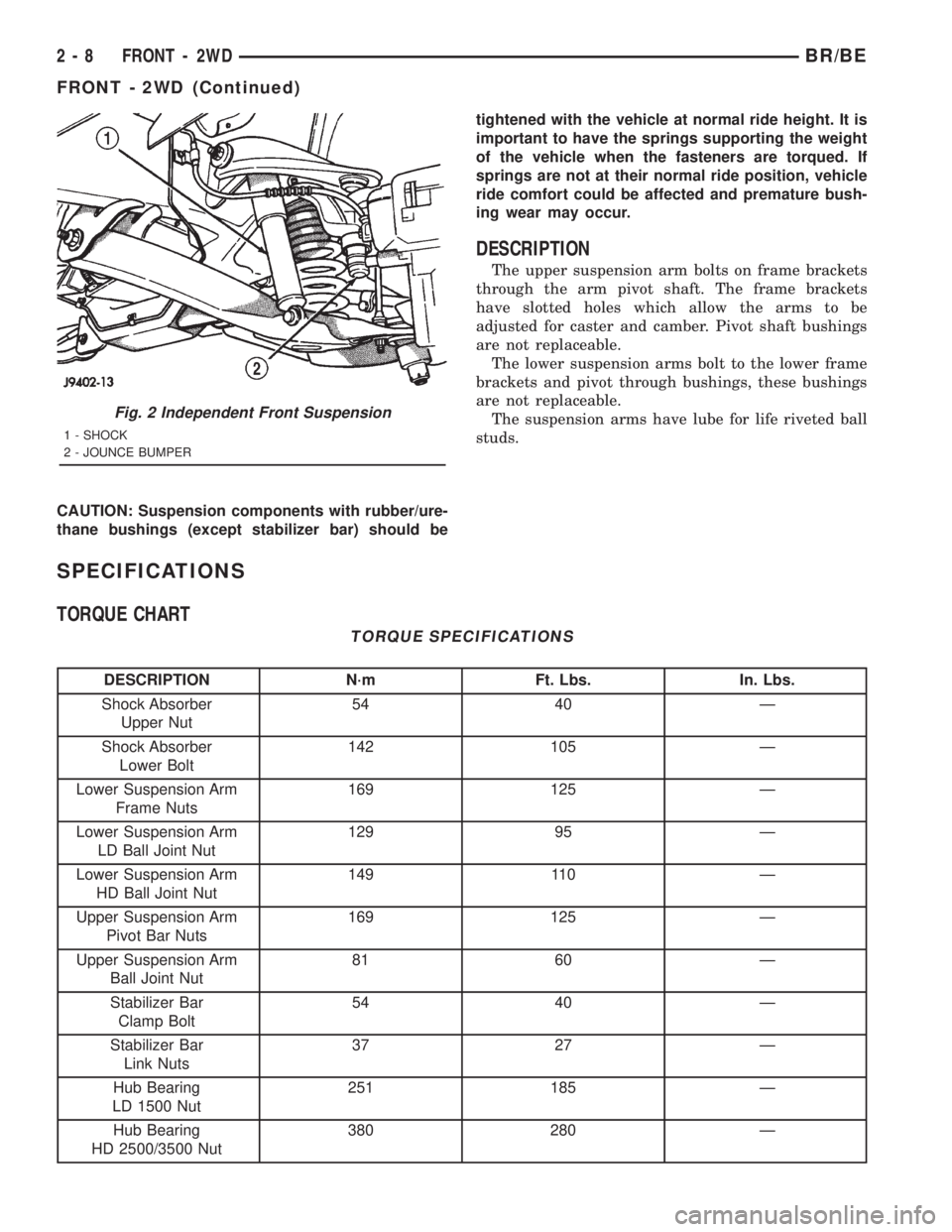
Fig. 2 Independent Front Suspension
1 - SHOCK
2 - JOUNCE BUMPER
2 - 8 FRONT - 2WDBR/BE
FRONT - 2WD (Continued)
Page 53 of 2889
OPERATION
The steering knuckles pivots between the upper
and lower ball joints. The steering linkage is
attached to the knuckles controls vehicle steering.
REMOVAL
(1) Raise and support the vehicle.
(2) Remove the wheel and tire assembly.
(3) Remove the brake caliper and rotor, (Refer to 5
- BRAKES/HYDRAULIC/MECHANICAL/DISC
BRAKE CALIPERS - REMOVAL).
(4) Remove the cotter pin and nut from the tie-rod
end. Remove the tie rod end from the knuckle with
Puller C-3894-A.
(5) Remove the cotter pins and nuts from the
upper and lower ball joints. Separate upper ball joint
from knuckle with remover MD-990635. Separate
lower ball joint with remover C-4150A and remove
knuckle.
INSTALLATION
(1) Position the knuckle on the ball joints and
install the ball joint nuts.
(2) Tighten the upper ball joint nut to 81 N´m (60
ft. lbs.) and install cotter pin.
(3) Tighten the lower ball joint nut to:
²LD: 129 N´m (95 ft. lbs.)
²HD: 149 N´m (110 ft. lbs.)
(3) Install the cotter pin.
(4) Install the tie rod end on the steering knuckle
and tighten the nut to 108 N´m (80 ft. lbs.). Install
cotter pin.
(5) Install the brake rotor and caliper, (Refer to 5 -
BRAKES/HYDRAULIC/MECHANICAL/DISC
BRAKE CALIPERS - INSTALLATION).
(6) Install wheel and tire assembly (Refer to 22 -
TIRES/WHEELS/WHEELS - STANDARD PROCE-
DURE).
(7) Remove support and lower vehicle.
LOWER BALL JOINT
DIAGNOSIS AND TESTING - LOWER BALL
JOINT
(1) Raise the front of the vehicle. Place safety floor
stands under both lower suspension arms as far out-
board as possible. Lower the vehicle to allow the
stands to support some or all of the vehicle weight.
NOTE: The upper suspension arms must not be in
maximum rebound position.
(2) Remove the tire and wheel assembly.
(3) Mount a dial indicator solidly under the lower
suspension arm.(4) Position indicator plunger against the bottom
of the steering knuckle lower ball joint boss.
NOTE: The dial Indicator plunger must be perpen-
dicular to the machined surface of the steering
knuckle lower ball joint boss.
(5) Position a pry bar over the top of the upper
suspension arm and under the pivot bar of the upper
suspension arm. Pry down on the upper suspension
arm and then zero the dial indicator.
(6) Reposition the pry bar under the upper suspen-
sion arm and on top of the frame rail. Pry up on the
upper suspension arm and record the dial indicator
reading.
(7) If the travel exceeds 0.8 mm (0.030 in.) replace
the suspension arm.
LOWER CONTROL ARM
REMOVAL
(1) Raise and support the vehicle.
(2) Remove the tire and wheel assembly.
(3) Remove the brake caliper assembly and rotor,
(Refer to 5 - BRAKES/HYDRAULIC/MECHANICAL/
ROTORS - REMOVAL).
(4) Remove the cotter pin and nut from the tie rod.
Remove the tie rod end from the steering knuckle
with Puller C-3894-A.
(5) Remove the stabilizer bar link from lower sus-
pension arm.
(6) Support the lower suspension arm outboard
end with jack. Place a jack under the arm in the
front of the shock mount.
(7) Remove the cotter pin and nut from the lower
ball joint. Separate the ball joint with Remover
C-4150A.
(8) Remove the lower shock bolt from the suspen-
sion arm.
(9) Lower the jack and suspension arm until
spring tension is relieved. Remove spring and rubber
isolator (Fig. 5).
(10) Remove bolts mounting suspension arm to
crossmember and remove arm.
INSTALLATION
(1) Position the suspension arm on the crossmem-
ber and install the bolts and nuts snug.
(2) Install the rubber isolator on top of the spring.
Position the spring into upper spring seat.
(3) Raise the lower suspension arm with a jack
and position the spring into the lower suspension
arm mount.
(4) Install the lower shock bolt and tighten to 142
N´m (105 ft. lbs.).
2 - 10 FRONT - 2WDBR/BE
KNUCKLE (Continued)
Page 55 of 2889
(3) Remove the brake caliper assembly and rotor,
(Refer to 5 - BRAKES/HYDRAULIC/MECHANICAL/
ROTORS - REMOVAL).
(4) Remove the cotter pin and nut from the tie rod.
Remove the tie rod end from the steering knuckle
with Puller C-3894-A.
(5) Remove the stabilizer bar link from the lower
suspension arm.
(6) Support the lower suspension arm outboard
end with a jack. Place a jack under the arm in front
of the shock mount.
(7) Remove the cotter pin and nut from the lower
ball joint. Separate the ball joint with Remover
C-4150A.
(8) Remove the lower shock bolt from the suspen-
sion arm.
(9) Lower the jack and suspension arm until
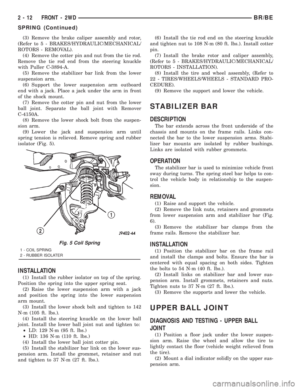
spring tension is relieved. Remove spring and rubber
isolator (Fig. 5).
INSTALLATION
(1) Install the rubber isolator on top of the spring.
Position the spring into the upper spring seat.
(2) Raise the lower suspension arm with a jack
and position the spring into the lower suspension
arm mount.
(3) Install the lower shock bolt and tighten to 142
N´m (105 ft. lbs.).
(4) Install the steering knuckle on the lower ball
joint. Install the lower ball joint nut and tighten to:
²LD: 129 N´m (95 ft. lbs.)
²HD: 136 N´m (110 ft. lbs.)
(4) Install the lower ball joint cotter pin.
(5) Install the stabilizer bar link on the lower sus-
pension arm. Install the grommet, retainer and nut
and tighten to 37 N´m (27 ft. lbs.).(6) Install the tie rod end on the steering knuckle
and tighten nut to 108 N´m (80 ft. lbs.). Install cotter
pin.
(7) Install the brake rotor and caliper assembly,
(Refer to 5 - BRAKES/HYDRAULIC/MECHANICAL/
ROTORS - INSTALLATION).
(8) Install the tire and wheel assembly, (Refer to
22 - TIRES/WHEELS/WHEELS - STANDARD PRO-
CEDURE).
(9) Remove the support and lower the vehicle.
STABILIZER BAR
DESCRIPTION
The bar extends across the front underside of the
chassis and mounts on the frame rails. Links con-
nected the bar to the lower suspension arms. Stabi-
lizer bar mounts are isolated by rubber bushings.
Links are isolated with rubber grommets.
OPERATION
The stabilizer bar is used to minimize vehicle front
sway during turns. The spring steel bar helps to con-
trol the vehicle body in relationship to the suspen-
sion.
REMOVAL
(1) Raise and support the vehicle.
(2) Remove the link nuts, retainers and grommets
from lower suspension arm and stabilizer bar (Fig.
6).
(3) Remove the stabilizer bar clamps from the
frame rails. Remove the stabilizer bar.
INSTALLATION
(1) Position the stabilizer bar on the frame rail
and install the clamps and bolts. Ensure the bar is
centered with equal spacing on both sides. Tighten
the bolts to 54 N´m (40 ft. lbs.).
(2) Install links on stabilizer bar and lower sus-
pension arm. Install grommets, retainers and nuts.
Tighten nuts to 37 N´m (27 ft. lbs.).
(3) Remove the supports and lower the vehicle.
UPPER BALL JOINT
DIAGNOSIS AND TESTING - UPPER BALL
JOINT
(1) Position a floor jack under the lower suspen-
sion arm. Raise the wheel and allow the tire to
lightly contact the floor (vehicle weight relieved from
the tire).
(2) Mount a dial indicator solidly on the upper sus-
pension arm.
Fig. 5 Coil Spring
1 - COIL SPRING
2 - RUBBER ISOLATER
2 - 12 FRONT - 2WDBR/BE
SPRING (Continued)
Page 57 of 2889
FRONT - 4WD
TABLE OF CONTENTS
page page
FRONT - 4WD
DESCRIPTION...........................14
SPECIFICATIONS........................15
SPECIAL TOOLS.........................16
HUB / BEARING
REMOVAL..............................16
INSTALLATION...........................18
KNUCKLE
DESCRIPTION...........................20
OPERATION.............................20
REMOVAL..............................20
INSTALLATION...........................20
LOWER CONTROL ARM
REMOVAL..............................20
INSTALLATION...........................20
SHOCK
DESCRIPTION...........................21
OPERATION.............................21
DIAGNOSIS AND TESTING.................21
SHOCK..............................21
REMOVAL..............................21
INSTALLATION...........................21
SPRING
DESCRIPTION...........................22OPERATION.............................22
REMOVAL..............................22
INSTALLATION...........................22
STABILIZER BAR
DESCRIPTION...........................22
OPERATION.............................22
REMOVAL..............................22
INSTALLATION...........................23
TRACK BAR
DESCRIPTION...........................23
OPERATION.............................23
DIAGNOSIS AND TESTING.................23
TRACK BAR...........................23
REMOVAL..............................23
INSTALLATION...........................23
UPPER CONTROL ARM
REMOVAL..............................23
INSTALLATION...........................24
LOWER BALL JOINT
REMOVAL..............................24
INSTALLATION...........................25
UPPER BALL JOINT
REMOVAL..............................25
INSTALLATION...........................25
FRONT - 4WD
DESCRIPTION
The link/coil suspension allows each wheel to adapt
to different road surfaces. The suspension is com-
prised of (Fig. 1) :
²Shock absorbers
²Coil springs
²Upper and lower suspension arms
²Stabilizer bar
²Track bar
²Steering Knuckles
²Hub/Bearing
²Ball Joints
²Jounce Bumpers
CAUTION: Components attached with a nut and cot-
ter pin must be torqued to specification. Then if the
slot in the nut does not line up with the cotter pin
hole, tighten nut until it is aligned. Never loosen the
nut to align the cotter pin hole.CAUTION: Suspension components with rubber
bushings (except stabilizer bar) should be tightened
with the vehicle at normal height. It is important to
have the springs supporting the weight of the vehi-
cle when the fasteners are torqued. If springs are
not at their normal ride position, vehicle ride com-
fort could be affected and premature bushing wear
may occur.
DESCRIPTION
The upper and lower suspension arms use bush-
ings to isolate road noise. The suspension arms are
bolted to the frame and axle through the rubber
bushings. The lower suspension arm uses cam bolts
at the axle to allow for caster and pinion angle
adjustment.
2 - 14 FRONT - 4WDBR/BE
Page 69 of 2889
REAR
TABLE OF CONTENTS
page page
REAR
DESCRIPTION...........................26
DIAGNOSIS AND TESTING.................26
SPRING AND SHOCK....................26
SPECIFICATIONS........................27
SPECIAL TOOLS.........................28
BUSHINGS
REMOVAL..............................28
INSTALLATION...........................28
JOUNCE BUMPER
DESCRIPTION...........................28
OPERATION.............................28
SHOCK
DESCRIPTION...........................28OPERATION.............................28
REMOVAL..............................28
INSTALLATION...........................28
SPRING
DESCRIPTION...........................28
OPERATION.............................28
REMOVAL..............................28
INSTALLATION...........................29
STABILIZER BAR
DESCRIPTION...........................30
OPERATION.............................30
REMOVAL..............................30
INSTALLATION...........................30
REAR
DESCRIPTION
The rear suspension is comprised of:
²Shock Absorbers
²Jounce Bumpers
²Stabilizer Bar (optional)
²Leaf Springs
²Drive Axle
CAUTION: A vehicle should always be loaded so
the vehicle weight center-line is located immedi-
ately forward of the rear axle. Correct vehicle load-
ing provides proper front tire-to-road contact. This
results in maximum vehicle handling stability and
safety. Incorrect vehicle weight distribution can
cause excessive tire tread wear, spring fatigue or
failure, and erratic steering.
CAUTION: Suspension components with rubber/ure-
thane bushings (except stabilizer bar) should be
tightened with the vehicle at normal ride height. It is
important to have the springs supporting the weight
of the vehicle when the fasteners are torqued. If
springs are not at their normal ride position, vehicle
ride comfort could be affected and premature bush-
ing wear may occur.
DIAGNOSIS AND TESTING - SPRING AND
SHOCK
A knocking or rattling noise from a shock absorber
may be caused by movement between mounting
bushings and metal brackets or attaching compo-
nents. These noises can usually be stopped by tight-
ening the attaching nuts. If the noise persists,
inspect for damaged and worn bushings, and attach-
ing components. Repair as necessary if any of these
conditions exist.
A squeaking noise from the shock absorber may be
caused by the hydraulic valving and may be intermit-
tent. This condition is not repairable and the shock
absorber must be replaced.
The shock absorbers are not refillable or adjust-
able. If a malfunction occurs, the shock absorber
must be replaced. To test a shock absorber, hold it in
an upright position and force the piston in and out of
the cylinder four or five times. The action throughout
each stroke should be smooth and even.
The spring eye and shock absorber bushings do not
require any type of lubrication. Do not attempt to
stop spring bushing noise by lubricating them.
Grease and mineral oil-base lubricants will deterio-
rate the bushing rubber.
If the vehicle is used for severe, off-road operation,
the springs should be examined periodically. Check
for broken and shifted leafs, loose and missing clips,
and broken center bolts. Refer to Spring and Shock
Absorber Diagnosis chart for additional information.
2 - 26 REARBR/BE
Page 71 of 2889
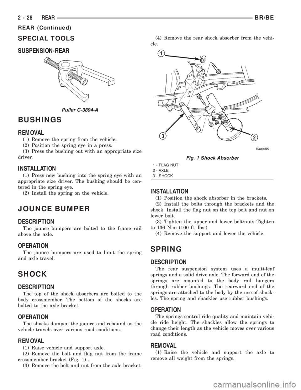
SPECIAL TOOLS
SUSPENSION-REAR
BUSHINGS
REMOVAL
(1) Remove the spring from the vehicle.
(2) Position the spring eye in a press.
(3) Press the bushing out with an appropriate size
driver.
INSTALLATION
(1) Press new bushing into the spring eye with an
appropriate size driver. The bushing should be cen-
tered in the spring eye.
(2) Install the spring on the vehicle.
JOUNCE BUMPER
DESCRIPTION
The jounce bumpers are bolted to the frame rail
above the axle.
OPERATION
The jounce bumpers are used to limit the spring
and axle travel.
SHOCK
DESCRIPTION
The top of the shock absorbers are bolted to the
body crossmember. The bottom of the shocks are
bolted to the axle bracket.
OPERATION
The shocks dampen the jounce and rebound as the
vehicle travels over various road conditions.
REMOVAL
(1) Raise vehicle and support axle.
(2) Remove the bolt and flag nut from the frame
crossmember bracket (Fig. 1) .
(3) Remove the bolt and nut from the axle bracket.(4) Remove the rear shock absorber from the vehi-
cle.
INSTALLATION
(1) Position the shock absorber in the brackets.
(2) Install the bolts through the brackets and the
shock. Install the flag nut on the top bolt and nut on
lower bolt.
(3) Tighten the upper and lower bolt/nuts Tighten
to 136 N.m (100 ft. lbs.)
(4) Remove the support and lower the vehicle.
SPRING
DESCRIPTION
The rear suspension system uses a multi-leaf
springs and a solid drive axle. The forward end of the
springs are mounted to the body rail hangers
through rubber bushings. The rearward end of the
springs are attached to the body by the use of shack-
les. The spring and shackles use rubber bushings.
OPERATION
The springs control ride quality and maintain vehi-
cle ride height. The shackles allow the springs to
change their length as the vehicle moves over various
road conditions.
REMOVAL
(1) Raise the vehicle and support the axle to
remove all weight from the springs.
Puller C-3894-A
Fig. 1 Shock Absorber
1 - FLAG NUT
2 - AXLE
3 - SHOCK
2 - 28 REARBR/BE
REAR (Continued)
Page 72 of 2889
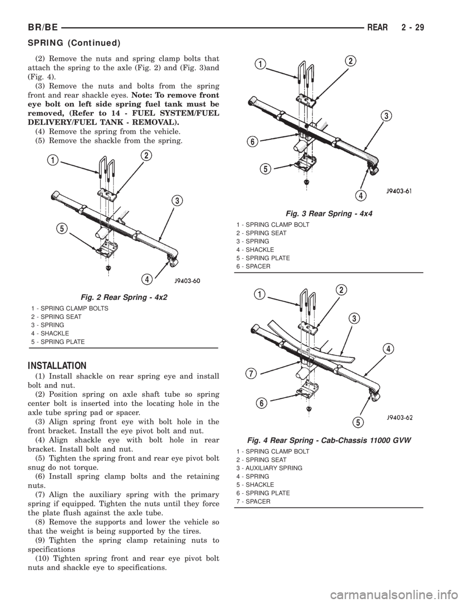
(2) Remove the nuts and spring clamp bolts that
attach the spring to the axle (Fig. 2) and (Fig. 3)and
(Fig. 4).
(3) Remove the nuts and bolts from the spring
front and rear shackle eyes.Note: To remove front
eye bolt on left side spring fuel tank must be
removed, (Refer to 14 - FUEL SYSTEM/FUEL
DELIVERY/FUEL TANK - REMOVAL).
(4) Remove the spring from the vehicle.
(5) Remove the shackle from the spring.
INSTALLATION
(1) Install shackle on rear spring eye and install
bolt and nut.
(2) Position spring on axle shaft tube so spring
center bolt is inserted into the locating hole in the
axle tube spring pad or spacer.
(3) Align spring front eye with bolt hole in the
front bracket. Install the eye pivot bolt and nut.
(4) Align shackle eye with bolt hole in rear
bracket. Install bolt and nut.
(5) Tighten the spring front and rear eye pivot bolt
snug do not torque.
(6) Install spring clamp bolts and the retaining
nuts.
(7) Align the auxiliary spring with the primary
spring if equipped. Tighten the nuts until they force
the plate flush against the axle tube.
(8) Remove the supports and lower the vehicle so
that the weight is being supported by the tires.
(9) Tighten the spring clamp retaining nuts to
specifications
(10) Tighten spring front and rear eye pivot bolt
nuts and shackle eye to specifications.
Fig. 2 Rear Spring - 4x2
1 - SPRING CLAMP BOLTS
2 - SPRING SEAT
3 - SPRING
4 - SHACKLE
5 - SPRING PLATE
Fig. 3 Rear Spring - 4x4
1 - SPRING CLAMP BOLT
2 - SPRING SEAT
3 - SPRING
4 - SHACKLE
5 - SPRING PLATE
6 - SPACER
Fig. 4 Rear Spring - Cab-Chassis 11000 GVW
1 - SPRING CLAMP BOLT
2 - SPRING SEAT
3 - AUXILIARY SPRING
4 - SPRING
5 - SHACKLE
6 - SPRING PLATE
7 - SPACER
BR/BEREAR 2 - 29
SPRING (Continued)