oil temperature DODGE RAM 2002 Service Owner's Manual
[x] Cancel search | Manufacturer: DODGE, Model Year: 2002, Model line: RAM, Model: DODGE RAM 2002Pages: 2255, PDF Size: 62.07 MB
Page 381 of 2255
The fuel pump is activated by the PCM through
the fuel pump relay.
Voltage is applied to the fuel injectors with the
ASD relay via the PCM. The PCM will then control
the injection sequence and injector pulse width by
turning the ground circuit to each individual injector
on and off.
The PCM determines the proper ignition timing
according to input received from the crankshaft posi-
tion sensor.
ENGINE WARM-UP MODE
This is an Open Loop mode. During engine warm-
up, the PCM receives inputs from:
²Battery voltage
²Crankshaft position sensor
²Engine coolant temperature sensor
²Intake manifold air temperature sensor
²Manifold absolute pressure (MAP) sensor
²Throttle position sensor (TPS)
²Camshaft position sensor signal (in the distribu-
tor)
²Park/neutral switch (gear indicator signalÐauto.
trans. only)
²Air conditioning select signal (if equipped)
²Air conditioning request signal (if equipped)
Based on these inputs the following occurs:
²Voltage is applied to the fuel injectors with the
ASD relay via the PCM. The PCM will then control
the injection sequence and injector pulse width by
turning the ground circuit to each individual injector
on and off.
²The PCM adjusts engine idle speed through the
idle air control (IAC) motor and adjusts ignition tim-
ing.
²The PCM operates the A/C compressor clutch
through the clutch relay. This is done if A/C has been
selected by the vehicle operator and requested by the
A/C thermostat.
²When engine has reached operating tempera-
ture, the PCM will begin monitoring O2S sensor
input. The system will then leave the warm-up mode
and go into closed loop operation.
IDLE MODE
When the engine is at operating temperature, this
is a Closed Loop mode. At idle speed, the PCM
receives inputs from:
²Air conditioning select signal (if equipped)
²Air conditioning request signal (if equipped)
²Battery voltage
²Crankshaft position sensor
²Engine coolant temperature sensor
²Intake manifold air temperature sensor
²Manifold absolute pressure (MAP) sensor
²Throttle position sensor (TPS)²Camshaft position sensor signal (in the distribu-
tor)
²Battery voltage
²Park/neutral switch (gear indicator signalÐauto.
trans. only)
²Oxygen sensors
Based on these inputs, the following occurs:
²Voltage is applied to the fuel injectors with the
ASD relay via the PCM. The PCM will then control
injection sequence and injector pulse width by turn-
ing the ground circuit to each individual injector on
and off.
²The PCM monitors the O2S sensor input and
adjusts air-fuel ratio by varying injector pulse width.
It also adjusts engine idle speed through the idle air
control (IAC) motor.
²The PCM adjusts ignition timing by increasing
and decreasing spark advance.
²The PCM operates the A/C compressor clutch
through the clutch relay. This happens if A/C has
been selected by the vehicle operator and requested
by the A/C thermostat.
CRUISE MODE
When the engine is at operating temperature, this
is a Closed Loop mode. At cruising speed, the PCM
receives inputs from:
²Air conditioning select signal (if equipped)
²Air conditioning request signal (if equipped)
²Battery voltage
²Engine coolant temperature sensor
²Crankshaft position sensor
²Intake manifold air temperature sensor
²Manifold absolute pressure (MAP) sensor
²Throttle position sensor (TPS)
²Camshaft position sensor signal (in the distribu-
tor)
²Park/neutral switch (gear indicator signalÐauto.
trans. only)
²Oxygen (O2S) sensors
Based on these inputs, the following occurs:
²Voltage is applied to the fuel injectors with the
ASD relay via the PCM. The PCM will then adjust
the injector pulse width by turning the ground circuit
to each individual injector on and off.
²The PCM monitors the O2S sensor input and
adjusts air-fuel ratio. It also adjusts engine idle
speed through the idle air control (IAC) motor.
²The PCM adjusts ignition timing by turning the
ground path to the coil on and off.
²The PCM operates the A/C compressor clutch
through the clutch relay. This happens if A/C has
been selected by the vehicle operator and requested
by the A/C thermostat.
8E - 16 ELECTRONIC CONTROL MODULESBR/BE
POWERTRAIN CONTROL MODULE (Continued)
Page 382 of 2255
ACCELERATION MODE
This is an Open Loop mode. The PCM recognizes
an abrupt increase in throttle position or MAP pres-
sure as a demand for increased engine output and
vehicle acceleration. The PCM increases injector
pulse width in response to increased throttle opening.
DECELERATION MODE
When the engine is at operating temperature, this
is an Open Loop mode. During hard deceleration, the
PCM receives the following inputs.
²Air conditioning select signal (if equipped)
²Air conditioning request signal (if equipped)
²Battery voltage
²Engine coolant temperature sensor
²Crankshaft position sensor
²Intake manifold air temperature sensor
²Manifold absolute pressure (MAP) sensor
²Throttle position sensor (TPS)
²Camshaft position sensor signal (in the distribu-
tor)
²Park/neutral switch (gear indicator signalÐauto.
trans. only)
²Vehicle speed sensor
If the vehicle is under hard deceleration with the
proper rpm and closed throttle conditions, the PCM
will ignore the oxygen sensor input signal. The PCM
will enter a fuel cut-off strategy in which it will not
supply a ground to the injectors. If a hard decelera-
tion does not exist, the PCM will determine the
proper injector pulse width and continue injection.
Based on the above inputs, the PCM will adjust
engine idle speed through the idle air control (IAC)
motor.
The PCM adjusts ignition timing by turning the
ground path to the coil on and off.
WIDE OPEN THROTTLE MODE
This is an Open Loop mode. During wide open
throttle operation, the PCM receives the following
inputs.
²Battery voltage
²Crankshaft position sensor
²Engine coolant temperature sensor
²Intake manifold air temperature sensor
²Manifold absolute pressure (MAP) sensor
²Throttle position sensor (TPS)
²Camshaft position sensor signal (in the distribu-
tor)
During wide open throttle conditions, the following
occurs:
²Voltage is applied to the fuel injectors with the
ASD relay via the PCM. The PCM will then controlthe injection sequence and injector pulse width by
turning the ground circuit to each individual injector
on and off. The PCM ignores the oxygen sensor input
signal and provides a predetermined amount of addi-
tional fuel. This is done by adjusting injector pulse
width.
²The PCM adjusts ignition timing by turning the
ground path to the coil on and off.
IGNITION SWITCH OFF MODE
When ignition switch is turned to OFF position,
the PCM stops operating the injectors, ignition coil,
ASD relay and fuel pump relay.
DESCRIPTION - 5 VOLT SUPPLIES
Two different Powertrain Control Module (PCM)
five volt supply circuits are used; primary and sec-
ondary.
DESCRIPTION - IGNITION CIRCUIT SENSE
This circuit ties the ignition switch to the Power-
train Control Module (PCM).
DESCRIPTION - POWER GROUNDS
The Powertrain Control Module (PCM) has 2 main
grounds. Both of these grounds are referred to as
power grounds. All of the high-current, noisy, electri-
cal devices are connected to these grounds as well as
all of the sensor returns. The sensor return comes
into the sensor return circuit, passes through noise
suppression, and is then connected to the power
ground.
The power ground is used to control ground cir-
cuits for the following PCM loads:
²Generator field winding
²Fuel injectors
²Ignition coil(s)
²Certain relays/solenoids
²Certain sensors
DESCRIPTION - SENSOR RETURN
The Sensor Return circuits are internal to the Pow-
ertrain Control Module (PCM).
Sensor Return provides a low±noise ground refer-
ence for all engine control system sensors. Refer to
Power Grounds for more information.
DESCRIPTION - SIGNAL GROUND
Signal ground provides a low noise ground to the
data link connector.
BR/BEELECTRONIC CONTROL MODULES 8E - 17
POWERTRAIN CONTROL MODULE (Continued)
Page 383 of 2255
OPERATION
OPERATION - PCM - GAS ENGINES
The PCM operates the fuel system. The PCM is a
pre-programmed, triple microprocessor digital com-
puter. It regulates ignition timing, air-fuel ratio,
emission control devices, charging system, certain
transmission features, speed control, air conditioning
compressor clutch engagement and idle speed. The
PCM can adapt its programming to meet changing
operating conditions.
The PCM receives input signals from various
switches and sensors. Based on these inputs, the
PCM regulates various engine and vehicle operations
through different system components. These compo-
nents are referred to as Powertrain Control Module
(PCM) Outputs. The sensors and switches that pro-
vide inputs to the PCM are considered Powertrain
Control Module (PCM) Inputs.
The PCM adjusts ignition timing based upon
inputs it receives from sensors that react to: engine
rpm, manifold absolute pressure, engine coolant tem-
perature, throttle position, transmission gear selec-
tion (automatic transmission), vehicle speed and the
brake switch.
The PCM adjusts idle speed based on inputs it
receives from sensors that react to: throttle position,
vehicle speed, transmission gear selection, engine
coolant temperature and from inputs it receives from
the air conditioning clutch switch and brake switch.
Based on inputs that it receives, the PCM adjusts
ignition coil dwell. The PCM also adjusts the gener-
ator charge rate through control of the generator
field and provides speed control operation.
NOTE: PCM Inputs:
²A/C request (if equipped with factory A/C)
²A/C select (if equipped with factory A/C)
²Auto shutdown (ASD) sense
²Battery temperature
²Battery voltage
²Brake switch
²CCD bus (+) circuits
²CCD bus (-) circuits
²Camshaft position sensor signal
²Crankshaft position sensor
²Data link connection for DRB scan tool
²Engine coolant temperature sensor
²Fuel level
²Generator (battery voltage) output
²Ignition circuit sense (ignition switch in on/off/
crank/run position)
²Intake manifold air temperature sensor
²Leak detection pump (switch) sense (if equipped)
²Manifold absolute pressure (MAP) sensor²Oil pressure
²Output shaft speed sensor
²Overdrive/override switch
²Oxygen sensors
²Park/neutral switch (auto. trans. only)
²Power ground
²Sensor return
²Signal ground
²Speed control multiplexed single wire input
²Throttle position sensor
²Transmission governor pressure sensor
²Transmission temperature sensor
²Vehicle speed inputs from ABS or RWAL system
NOTE: PCM Outputs:
²A/C clutch relay
²Auto shutdown (ASD) relay
²CCD bus (+/-) circuits for: speedometer, voltme-
ter, fuel gauge, oil pressure gauge/lamp, engine temp.
gauge and speed control warn. lamp
²Data link connection for DRB scan tool
²EGR valve control solenoid (if equipped)
²EVAP canister purge solenoid
²Five volt sensor supply (primary)
²Five volt sensor supply (secondary)
²Fuel injectors
²Fuel pump relay
²Generator field driver (-)
²Generator field driver (+)
²Generator lamp (if equipped)
²Idle air control (IAC) motor
²Ignition coil
²Leak detection pump (if equipped)
²Malfunction indicator lamp (Check engine lamp).
Driven through CCD circuits.
²Overdrive indicator lamp (if equipped)
²Service Reminder Indicator (SRI) Lamp (MAINT
REQ'D lamp). Driven through CCD circuits.
²Speed control vacuum solenoid
²Speed control vent solenoid
²Tachometer (if equipped). Driven through CCD
circuits.
²Transmission convertor clutch circuit
²Transmission 3±4 shift solenoid
²Transmission relay
²Transmission temperature lamp (if equipped)
²Transmission variable force solenoid
OPERATION - DIESEL
Two different control modules are used: The Pow-
ertrain Control Module (PCM), and the Engine Con-
trol Module (ECM). The ECMcontrolsthe fuel
system. The PCMdoes not controlthe fuel system.
The PCM's main function is to control: the vehicle
charging system, speed control system, transmission,
air conditioning system and certain bussed messages.
8E - 18 ELECTRONIC CONTROL MODULESBR/BE
POWERTRAIN CONTROL MODULE (Continued)
Page 384 of 2255
The PCM can adapt its programming to meet
changing operating conditions.
The PCM receives input signals from various
switches and sensors. Based on these inputs, the
PCM regulates various engine and vehicle operations
through different system components. These compo-
nents are referred to asPCM Outputs.The sensors
and switches that provide inputs to the PCM are con-
sideredPCM Inputs.
NOTE: PCM Inputs:
²A/C request (if equipped with factory A/C)
²A/C select (if equipped with factory A/C)
²Accelerator Pedal Position Sensor (APPS) output
from ECM
²Auto shutdown (ASD) relay sense
²Battery temperature sensor
²Battery voltage
²Brake switch
²CCD bus (+) circuits
²CCD bus (-) circuits
²Crankshaft Position Sensor (CKP) output from
ECM
²Data link connection for DRB scan tool
²Fuel level sensor
²Generator (battery voltage) output
²Ignition sense
²Output shaft speed sensor
²Overdrive/override switch
²Park/neutral switch (auto. trans. only)
²Power ground
²Sensor return
²Signal ground
²Speed control resume switch
²Speed control set switch
²Speed control on/off switch
²Transmission governor pressure sensor
²Transmission temperature sensor
²Vehicle speed inputs from ABS or RWAL system
NOTE: PCM Outputs:
After inputs are received by the PCM, certain sen-
sors, switches and components are controlled or reg-
ulated by the PCM. These are consideredPCM
Outputs.These outputs are for:
²A/C clutch relay and A/C clutch
²Auto shutdown (ASD) relay
²CCD bus (+/-) circuits for: speedometer, voltme-
ter, fuel gauge, oil pressure gauge/lamp, engine temp.
gauge and speed control warn. lamp
²Data link connection for DRB scan tool
²Five volt sensor supply
²Generator field driver (-)
²Generator field driver (+)
²Generator lamp (if equipped)²Malfunction indicator lamp (Check engine lamp)
²Overdrive warning lamp (if equipped)
²Speed control vacuum solenoid
²Speed control vent solenoid
²Tachometer (if equipped)
²Transmission convertor clutch circuit
²Transmission 3±4 shift solenoid
²Transmission relay
²Transmission temperature lamp (if equipped)
²Transmission variable force solenoid (governor
sol.)
OPERATION - 5 VOLT SUPPLIES
Primary 5±volt supply:
²supplies the required 5 volt power source to the
Crankshaft Position (CKP) sensor.
²supplies the required 5 volt power source to the
Camshaft Position (CMP) sensor.
²supplies a reference voltage for the Manifold
Absolute Pressure (MAP) sensor.
²supplies a reference voltage for the Throttle
Position Sensor (TPS) sensor.
Secondary 5±volt supply:
²supplies the required 5 volt power source to the
oil pressure sensor.
²supplies the required 5 volt power source for the
Vehicle Speed Sensor (VSS) (if equipped).
²supplies the 5 volt power source to the transmis-
sion pressure sensor (if equipped with an RE auto-
matic transmission).
OPERATION - IGNITION CIRCUIT SENSE
The ignition circuit sense input tells the PCM the
ignition switch has energized the ignition circuit.
Battery voltage is also supplied to the PCM
through the ignition switch when the ignition is in
the RUN or START position. This is referred to as
the9ignition sense9circuit and is used to9wake up9
the PCM. Voltage on the ignition input can be as low
as 6 volts and the PCM will still function. Voltage is
supplied to this circuit to power the PCM's 8-volt reg-
ulator and to allow the PCM to perform fuel, ignition
and emissions control functions.
REMOVAL
USE THE DRB SCAN TOOL TO REPROGRAM
THE NEW POWERTRAIN CONTROL MODULE
(PCM) WITH THE VEHICLES ORIGINAL IDEN-
TIFICATION NUMBER (VIN) AND THE VEHI-
CLES ORIGINAL MILEAGE. IF THIS STEP IS
NOT DONE, A DIAGNOSTIC TROUBLE CODE
(DTC) MAY BE SET.
The PCM is located in the engine compartment
(Fig. 18).
BR/BEELECTRONIC CONTROL MODULES 8E - 19
POWERTRAIN CONTROL MODULE (Continued)
Page 414 of 2255
CHARGING
TABLE OF CONTENTS
page page
CHARGING
DESCRIPTION.........................25
OPERATION...........................25
DIAGNOSIS AND TESTING - CHARGING
SYSTEM............................25
SPECIFICATIONS
GENERATOR RATINGS.................26
SPECIFICATIONS - TORQUE -
GENERATOR/CHARGING SYSTEM........27
BATTERY TEMPERATURE SENSOR
DESCRIPTION.........................27OPERATION...........................27
REMOVAL.............................27
INSTALLATION.........................28
GENERATOR
DESCRIPTION.........................28
OPERATION...........................28
REMOVAL.............................28
INSTALLATION.........................30
VOLTAGE REGULATOR
DESCRIPTION.........................30
OPERATION...........................30
CHARGING
DESCRIPTION
The charging system consists of:
²Generator
²Electronic Voltage Regulator (EVR) circuitry
within the Powertrain Control Module (PCM)
²Ignition switch
²Battery (refer to 8, Battery for information)
²Battery temperature sensor
²Check Gauges Lamp (if equipped)
²Voltmeter (refer to 8, Instrument Panel and
Gauges for information)
²Wiring harness and connections (refer to 8, Wir-
ing Diagrams for information)
OPERATION
The charging system is turned on and off with the
ignition switch. The system is on when the engine is
running and the ASD relay is energized. When the
ASD relay is on, voltage is supplied to the ASD relay
sense circuit at the PCM. This voltage is connected
through the PCM and supplied to one of the genera-
tor field terminals (Gen. Source +) at the back of the
generator.
The amount of direct current produced by the gen-
erator is controlled by the EVR (field control) cir-
cuitry contained within the PCM. This circuitry is
connected in series with the second rotor field termi-
nal and ground.
A battery temperature sensor, located in the bat-
tery tray housing, is used to sense battery tempera-
ture. This temperature data, along with data from
monitored line voltage, is used by the PCM to vary
the battery charging rate. This is done by cycling theground path to control the strength of the rotor mag-
netic field. The PCM then compensates and regulates
generator current output accordingly.
All vehicles are equipped with On-Board Diagnos-
tics (OBD). All OBD-sensed systems, including EVR
(field control) circuitry, are monitored by the PCM.
Each monitored circuit is assigned a Diagnostic Trou-
ble Code (DTC). The PCM will store a DTC in elec-
tronic memory for certain failures it detects. Refer to
On-Board Diagnostics in 25, Emission Control Sys-
tem for more DTC information and a list of codes.
The Check Gauges Lamp (if equipped) monitors:
charging system voltage,engine coolant tempera-
ture and engine oil pressure. If an extreme condition
is indicated, the lamp will be illuminated. This is
done as reminder to check the three gauges. The sig-
nal to activate the lamp is sent via the CCD bus cir-
cuits. The lamp is located on the instrument panel.
Refer to 8, Instrument Panel and Gauges for addi-
tional information.
DIAGNOSIS AND TESTING - CHARGING
SYSTEM
The following procedures may be used to diagnose
the charging system if:
²the check gauges lamp (if equipped) is illumi-
nated with the engine running
²the voltmeter (if equipped) does not register
properly
²an undercharged or overcharged battery condi-
tion occurs.
Remember that an undercharged battery is often
caused by:
²accessories being left on with the engine not
running
BR/BECHARGING 8F - 25
Page 417 of 2255
(2) Disconnect sensor pigtail harness from engine
wire harness.
(3) Pry sensor straight up from battery tray
mounting hole.
INSTALLATION
The battery temperature sensor is located under
the vehicle battery (Fig. 1) and is attached (snapped
into) a mounting hole on battery tray. On models
equipped with a diesel engine (dual batteries), only
one sensor is used. The sensor is located under the
battery on drivers side of vehicle.
(1) Feed pigtail harness through mounting hole in
top of battery tray and press sensor into top of tray
(snaps in).
(2) Connect pigtail harness.
(3) Install battery. Refer to 8A, Battery for proce-
dures.
GENERATOR
DESCRIPTION
The generator is belt-driven by the engine using a
serpentine type drive belt. It is serviced only as a
complete assembly. If the generator fails for any rea-
son, the entire assembly must be replaced.
OPERATION
As the energized rotor begins to rotate within the
generator, the spinning magnetic field induces a cur-
rent into the windings of the stator coil. Once the
generator begins producing sufficient current, it also
provides the current needed to energize the rotor.
The Y type stator winding connections deliver the
induced alternating current to 3 positive and 3 neg-
ative diodes for rectification. From the diodes, recti-
fied direct current is delivered to the vehicle
electrical system through the generator battery ter-
minal.
Although the generators appear the same exter-
nally, different generators with different output rat-
ings are used on this vehicle. Be certain that the
replacement generator has the same output rating
and part number as the original unit. Refer to Gen-
erator Ratings in the Specifications section at the
back of this group for amperage ratings and part
numbers.
Noise emitting from the generator may be caused
by: worn, loose or defective bearings; a loose or defec-
tive drive pulley; incorrect, worn, damaged or misad-
justed fan drive belt; loose mounting bolts; a
misaligned drive pulley or a defective stator or diode.
REMOVAL
WARNING: DISCONNECT NEGATIVE CABLE FROM
BATTERY BEFORE REMOVING BATTERY OUTPUT
WIRE (B+ WIRE) FROM GENERATOR. FAILURE TO
DO SO CAN RESULT IN INJURY OR DAMAGE TO
ELECTRICAL SYSTEM.
(1) Disconnect negative battery cable at battery.
Diesel Engines: Disconnect both negative battery
cables at both batteries.
(2) Remove generator drive belt. Refer to 7, Cool-
ing System for procedure.
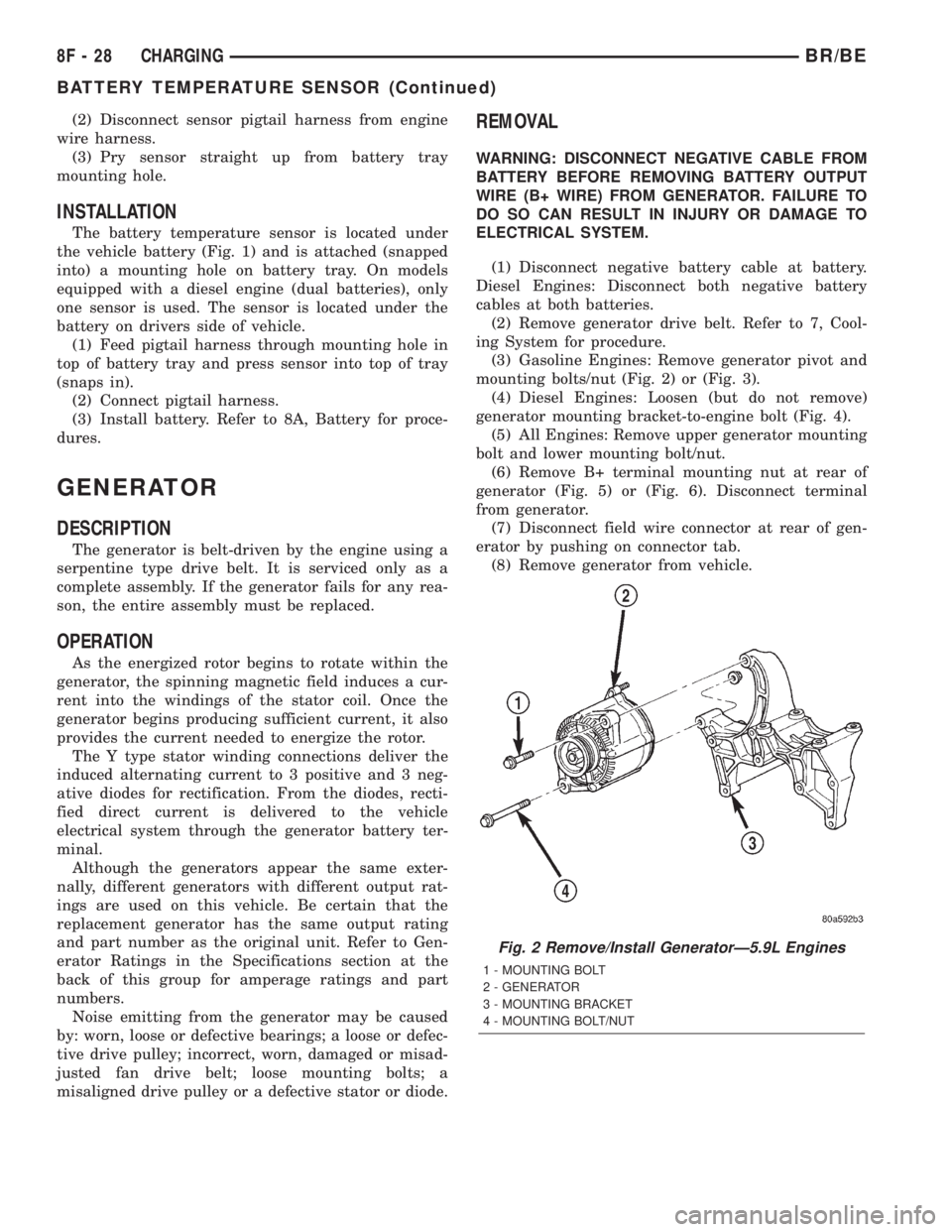
(3) Gasoline Engines: Remove generator pivot and
mounting bolts/nut (Fig. 2) or (Fig. 3).
(4) Diesel Engines: Loosen (but do not remove)
generator mounting bracket-to-engine bolt (Fig. 4).
(5) All Engines: Remove upper generator mounting
bolt and lower mounting bolt/nut.
(6) Remove B+ terminal mounting nut at rear of
generator (Fig. 5) or (Fig. 6). Disconnect terminal
from generator.
(7) Disconnect field wire connector at rear of gen-
erator by pushing on connector tab.
(8) Remove generator from vehicle.
Fig. 2 Remove/Install GeneratorÐ5.9L Engines
1 - MOUNTING BOLT
2 - GENERATOR
3 - MOUNTING BRACKET
4 - MOUNTING BOLT/NUT
8F - 28 CHARGINGBR/BE
BATTERY TEMPERATURE SENSOR (Continued)
Page 426 of 2255
Starter Motor and Solenoid
Solenoid Closing Maximum
Voltage Required7.5 Volts 7.5 Volts 8.0 Volts
* Cranking Amperage Draw
Test125 - 250 Amperes 125 - 250 Amperes 450 - 700 Amperes
* Test at operating temperature. Cold engine, tight (new) engine, or heavy oil will increase starter amperage draw.
SPECIFICATIONS - TORQUE - STARTING
SYSTEM
DESCRIPTION N´m Ft. Lbs. In. Lbs.
Battery Cable Eyelet Nut
at Solenoid (large nut -
gas engines)25 19 221
Battery Cable Eyelet Nut
at Solenoid (large nut -
diesel engine)14 - 120
Starter Solenoid Nut
(small nut - diesel engine)6-55
Starter Mounting Bolts -
Gas Engines68 50 -
Starter Mounting Nut -
Gas Engines68 50 -
Starter Mounting Bolts -
Diesel43 32 -
STARTER MOTOR
DESCRIPTION
The starter motors used for the 5.9L diesel engine
and the 8.0L gasoline engine available in this model
are not interchangeable with each other, or with the
starter motors used for the other available engines.
The starter motor for the 5.9L diesel engine is
mounted with three screws to the flywheel housing
on the left side of the engine. The starter motor for
the 8.0L gasoline engine is mounted with two screws
to the flange on the left rear corner of the engine
block, while the starter motor for the 5.9L Gas
engine is mounted with one screw, a stud and a nut
to the manual transmission clutch housing or auto-
matic transmission torque converter housing and is
located on the left side of the engine.
Each of these starter motors incorporates several
of the same features to create a reliable, efficient,
compact, lightweight and powerful unit. The electric
motors of all of these starters have four brushes con-
tacting the motor commutator, and feature four elec-
tromagnetic field coils wound around four pole shoes.
The 5.9L and 8.0L gasoline engine starter motors are
rated at 1.4 kilowatts (about 1.9 horsepower) outputat 12 volts, while the 5.9L diesel engine starter
motor is rated at 2.7 kilowatts (about 3.6 horse-
power) output at 12 volts.
All of these starter motors are serviced only as a
unit with their starter solenoids, and cannot be
repaired. If either component is faulty or damaged,
the entire starter motor and starter solenoid unit
must be replaced.
OPERATION
These starter motors are equipped with a gear
reduction (intermediate transmission) system. The
gear reduction system consists of a gear that is inte-
gral to the output end of the electric motor armature
shaft that is in continual engagement with a larger
gear that is splined to the input end of the starter
pinion gear shaft. This feature makes it possible to
reduce the dimensions of the starter. At the same
time, it allows higher armature rotational speed and
delivers increased torque through the starter pinion
gear to the starter ring gear.
The starter motors for all engines are activated by
an integral heavy duty starter solenoid switch
mounted to the overrunning clutch housing. This
electromechanical switch connects and disconnects
BR/BESTARTING 8F - 37
STARTING (Continued)
Page 470 of 2255
INSTALLATION
If engine has been cranked while distributor is
removed, establish the relationship between distribu-
tor shaft and number one piston position as follows:
Rotate crankshaft in a clockwise direction, as
viewed from front, until number one cylinder piston
is at top of compression stroke (compression should
be felt on finger with number one spark plug
removed). Then continue to slowly rotate engine
clockwise until indicating mark (Fig. 18) is aligned to
0 degree (TDC) mark on timing chain cover.
(1) Clean top of cylinder block for a good seal
between distributor base and block.
(2) Lightly oil the rubber o-ring seal on the distrib-
utor housing.
(3) Install rotor to distributor shaft.
(4) Position distributor into engine to its original
position. Engage tongue of distributor shaft with slot
in distributor oil pump drive gear. Position rotor to
the number one spark plug cable position.
(5) Install distributor holddown clamp and clamp
bolt. Do not tighten bolt at this time.
(6) Rotate the distributor housing until rotor is
aligned to CYL. NO. 1 alignment mark on the cam-
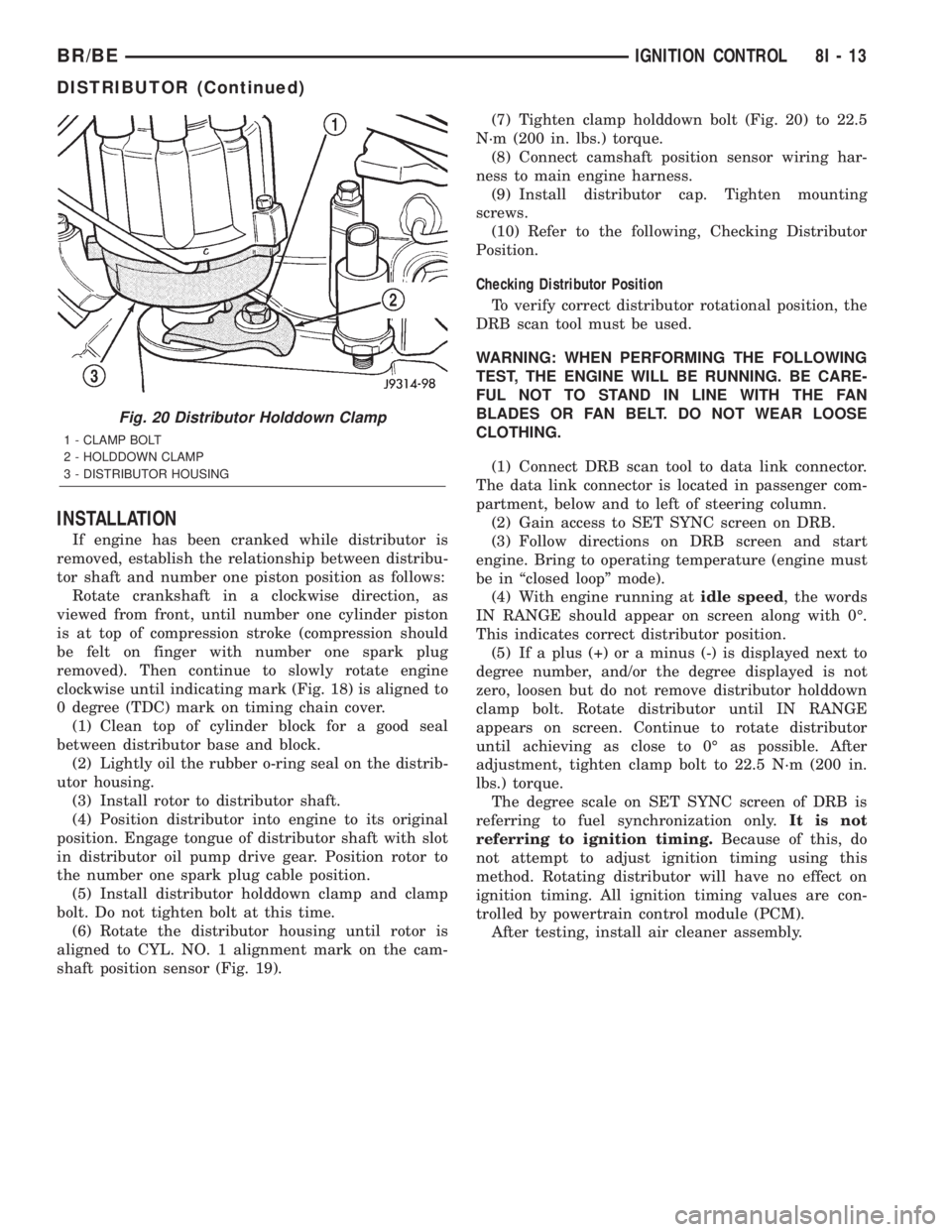
shaft position sensor (Fig. 19).(7) Tighten clamp holddown bolt (Fig. 20) to 22.5
N´m (200 in. lbs.) torque.
(8) Connect camshaft position sensor wiring har-
ness to main engine harness.
(9) Install distributor cap. Tighten mounting
screws.
(10) Refer to the following, Checking Distributor
Position.
Checking Distributor Position
To verify correct distributor rotational position, the
DRB scan tool must be used.
WARNING: WHEN PERFORMING THE FOLLOWING
TEST, THE ENGINE WILL BE RUNNING. BE CARE-
FUL NOT TO STAND IN LINE WITH THE FAN
BLADES OR FAN BELT. DO NOT WEAR LOOSE
CLOTHING.
(1) Connect DRB scan tool to data link connector.
The data link connector is located in passenger com-
partment, below and to left of steering column.
(2) Gain access to SET SYNC screen on DRB.
(3) Follow directions on DRB screen and start
engine. Bring to operating temperature (engine must
be in ªclosed loopº mode).
(4) With engine running atidle speed, the words
IN RANGE should appear on screen along with 0É.
This indicates correct distributor position.
(5) If a plus (+) or a minus (-) is displayed next to
degree number, and/or the degree displayed is not
zero, loosen but do not remove distributor holddown
clamp bolt. Rotate distributor until IN RANGE
appears on screen. Continue to rotate distributor
until achieving as close to 0É as possible. After
adjustment, tighten clamp bolt to 22.5 N´m (200 in.
lbs.) torque.
The degree scale on SET SYNC screen of DRB is
referring to fuel synchronization only.It is not
referring to ignition timing.Because of this, do
not attempt to adjust ignition timing using this
method. Rotating distributor will have no effect on
ignition timing. All ignition timing values are con-
trolled by powertrain control module (PCM).
After testing, install air cleaner assembly.
Fig. 20 Distributor Holddown Clamp
1 - CLAMP BOLT
2 - HOLDDOWN CLAMP
3 - DISTRIBUTOR HOUSING
BR/BEIGNITION CONTROL 8I - 13
DISTRIBUTOR (Continued)
Page 472 of 2255
IGNITION COIL
DESCRIPTION
DESCRIPTION - 5.9L
A single ignition coil is used. The coil is not oil
filled. The coil windings are embedded in an epoxy
compound. This provides heat and vibration resis-
tance that allows the coil to be mounted on the
engine.
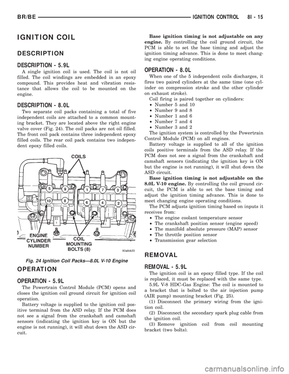
DESCRIPTION - 8.0L
Two separate coil packs containing a total of five
independent coils are attached to a common mount-
ing bracket. They are located above the right engine
valve cover (Fig. 24). The coil packs are not oil filled.
The front coil pack contains three independent epoxy
filled coils. The rear coil pack contains two indepen-
dent epoxy filled coils.
OPERATION
OPERATION - 5.9L
The Powertrain Control Module (PCM) opens and
closes the ignition coil ground circuit for ignition coil
operation.
Battery voltage is supplied to the ignition coil pos-
itive terminal from the ASD relay. If the PCM does
not see a signal from the crankshaft and camshaft
sensors (indicating the ignition key is ON but the
engine is not running), it will shut down the ASD cir-
cuit.Base ignition timing is not adjustable on any
engine.By controlling the coil ground circuit, the
PCM is able to set the base timing and adjust the
ignition timing advance. This is done to meet chang-
ing engine operating conditions.
OPERATION - 8.0L
When one of the 5 independent coils discharges, it
fires two paired cylinders at the same time (one cyl-
inder on compression stroke and the other cylinder
on exhaust stroke).
Coil firing is paired together on cylinders:
²Number 5 and 10
²Number 9 and 8
²Number 1 and 6
²Number 7 and 4
²Number 3 and 2
The ignition system is controlled by the Powertrain
Control Module (PCM) on all engines.
Battery voltage is supplied to all of the ignition
coils positive terminals from the ASD relay. If the
PCM does not see a signal from the crankshaft and
camshaft sensors (indicating the ignition key is ON
but the engine is not running), it will shut down the
ASD circuit.
Base ignition timing is not adjustable on the
8.0L V-10 engine.By controlling the coil ground cir-
cuit, the PCM is able to set the base timing and
adjust the ignition timing advance. This is done to
meet changing engine operating conditions.
The PCM adjusts ignition timing based on inputs it
receives from:
²The engine coolant temperature sensor
²The crankshaft position sensor (engine speed)
²The manifold absolute pressure (MAP) sensor
²The throttle position sensor
²Transmission gear selection
REMOVAL
REMOVAL - 5.9L
The ignition coil is an epoxy filled type. If the coil
is replaced, it must be replaced with the same type.
5.9L V-8 HDC-Gas Engine: The coil is mounted to
a bracket that is bolted to the air injection pump
(AIR pump) mounting bracket (Fig. 25).
(1) Disconnect the primary wiring from the igni-
tion coil.
(2) Disconnect the secondary spark plug cable from
the ignition coil.
(3) Remove ignition coil from coil mounting
bracket (two bolts).
Fig. 24 Ignition Coil PacksÐ8.0L V-10 Engine
BR/BEIGNITION CONTROL 8I - 15
Page 475 of 2255
cause of oil entry into that particular combustion
chamber.
ELECTRODE GAP BRIDGING
Electrode gap bridging may be traced to loose
deposits in the combustion chamber. These deposits
accumulate on the spark plugs during continuous
stop-and-go driving. When the engine is suddenly
subjected to a high torque load, deposits partially liq-
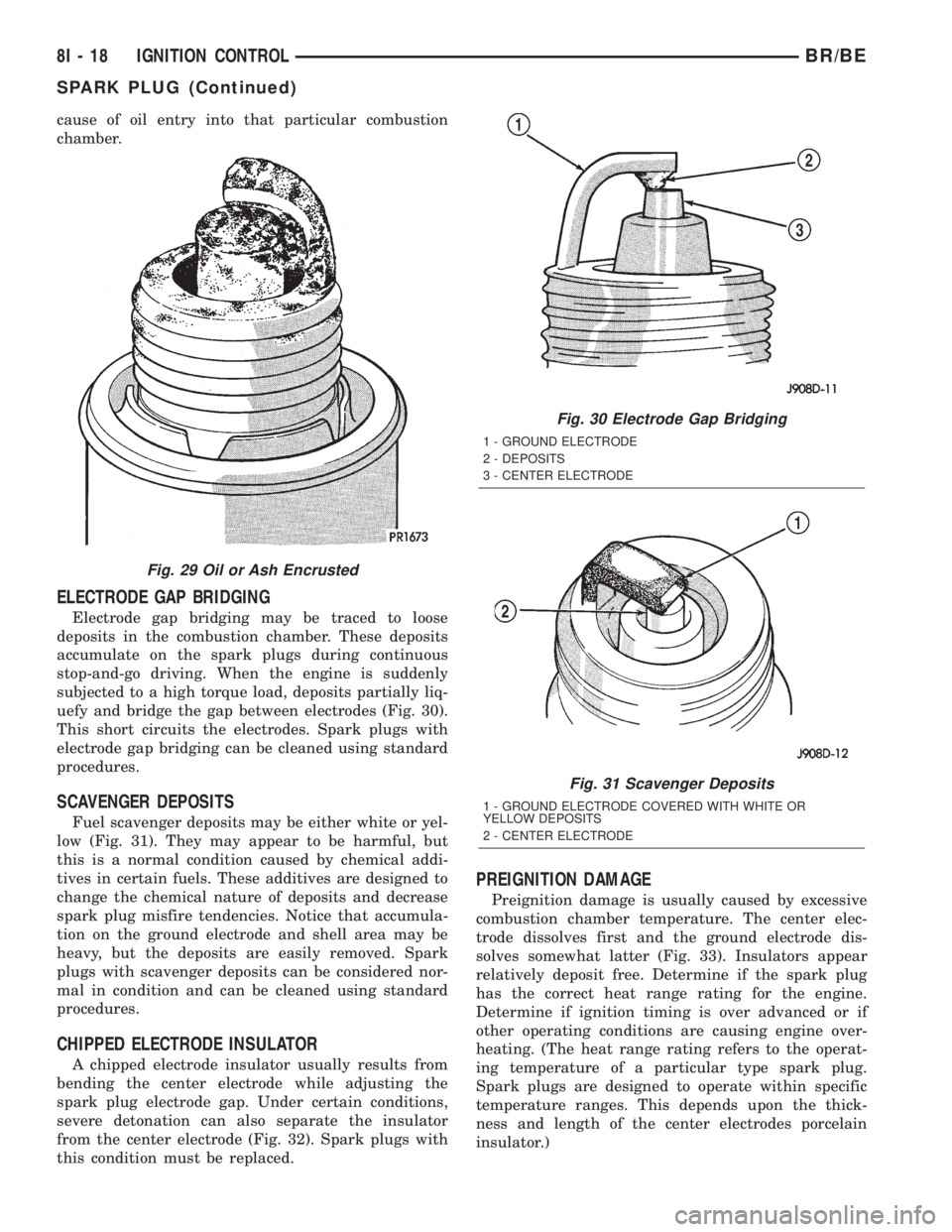
uefy and bridge the gap between electrodes (Fig. 30).
This short circuits the electrodes. Spark plugs with
electrode gap bridging can be cleaned using standard
procedures.
SCAVENGER DEPOSITS
Fuel scavenger deposits may be either white or yel-
low (Fig. 31). They may appear to be harmful, but
this is a normal condition caused by chemical addi-
tives in certain fuels. These additives are designed to
change the chemical nature of deposits and decrease
spark plug misfire tendencies. Notice that accumula-
tion on the ground electrode and shell area may be
heavy, but the deposits are easily removed. Spark
plugs with scavenger deposits can be considered nor-
mal in condition and can be cleaned using standard
procedures.
CHIPPED ELECTRODE INSULATOR
A chipped electrode insulator usually results from
bending the center electrode while adjusting the
spark plug electrode gap. Under certain conditions,
severe detonation can also separate the insulator
from the center electrode (Fig. 32). Spark plugs with
this condition must be replaced.
PREIGNITION DAMAGE
Preignition damage is usually caused by excessive
combustion chamber temperature. The center elec-
trode dissolves first and the ground electrode dis-
solves somewhat latter (Fig. 33). Insulators appear
relatively deposit free. Determine if the spark plug
has the correct heat range rating for the engine.
Determine if ignition timing is over advanced or if
other operating conditions are causing engine over-
heating. (The heat range rating refers to the operat-
ing temperature of a particular type spark plug.
Spark plugs are designed to operate within specific
temperature ranges. This depends upon the thick-
ness and length of the center electrodes porcelain
insulator.)
Fig. 29 Oil or Ash Encrusted
Fig. 30 Electrode Gap Bridging
1 - GROUND ELECTRODE
2 - DEPOSITS
3 - CENTER ELECTRODE
Fig. 31 Scavenger Deposits
1 - GROUND ELECTRODE COVERED WITH WHITE OR
YELLOW DEPOSITS
2 - CENTER ELECTRODE
8I - 18 IGNITION CONTROLBR/BE
SPARK PLUG (Continued)