steering gear DODGE RAM 2002 Service Owner's Manual
[x] Cancel search | Manufacturer: DODGE, Model Year: 2002, Model line: RAM, Model: DODGE RAM 2002Pages: 2255, PDF Size: 62.07 MB
Page 603 of 2255
WARNING: DURING AND FOLLOWING ANY SEAT
BELT SERVICE, CAREFULLY INSPECT ALL SEAT
BELTS, BUCKLES, MOUNTING HARDWARE, AND
RETRACTORS FOR PROPER INSTALLATION,
OPERATION, OR DAMAGE. REPLACE ANY BELT
THAT IS CUT, FRAYED, OR TORN. STRAIGHTEN
ANY BELT THAT IS TWISTED. TIGHTEN ANY
LOOSE FASTENERS. REPLACE ANY BELT THAT
HAS A DAMAGED OR INOPERATIVE BUCKLE OR
RETRACTOR. REPLACE ANY BELT THAT HAS A
BENT OR DAMAGED LATCH PLATE OR ANCHOR
PLATE. NEVER ATTEMPT TO REPAIR A SEAT BELT
COMPONENT. ALWAYS REPLACE DAMAGED OR
FAULTY SEAT BELT COMPONENTS WITH THE COR-
RECT, NEW AND UNUSED REPLACEMENT PARTS
LISTED IN THE MOPAR PARTS CATALOG.
(1) Position the child tether anchor (standard cab)
or child tether (club/quad cab) onto the cab back
panel (Fig. 7).
(2) Install and tighten the screw that secures the
child tether anchor (standard cab) or child tether
(club/quad cab) onto the cab back panel. Tighten the
screw to 13.5 N´m (120 in. lbs.).
(3) Reinstall the trim onto the inside of the cab
back panel. (Refer to 23 - BODY/INTERIOR/REAR
CLOSURE PANEL TRIM - INSTALLATION).
CLOCKSPRING
DESCRIPTION
The clockspring assembly is secured with two inte-
gral plastic latches onto the steering column lock
housing near the top of the steering column, behind
the steering wheel. The clockspring consists of a flat,
round molded plastic case with a stubby tail that
hangs below the steering column and contains a con-
nector receptacle and a long pigtail wire with connec-
tor that face toward the instrument panel. Within
the plastic housing is a spool-like molded plastic
rotor with a large exposed hub. The upper surface of
the rotor hub has a large center hole, two large flats,
two auto-locking tabs, and three short pigtail wires
with connectors that face toward the steering wheel.
The lower surface of the rotor hub has two integral
turn signal cancelling cam lobes. Within the plastic
case and wound around the rotor spool is a long rib-
bon-like tape that consists of several thin copper wire
leads sandwiched between two thin plastic mem-
branes. The outer end of the tape terminates at the
connector receptacle and pigtail wire that face the
instrument panel, while the inner end of the tape
terminates at the pigtail wires on the hub of the
clockspring rotor that face the steering wheel.
Service replacement clocksprings are shipped pre-
centered and with a piece of tape covering theengaged auto-locking tabs. The auto-locking tabs
secure the centered clockspring rotor to the clock-
spring case during shipment, but these tabs are auto-
matically disengaged once the clockspring is installed
on the steering column. (Refer to 8 - ELECTRICAL/
RESTRAINTS/CLOCKSPRING - STANDARD PRO-
CEDURE - CLOCKSPRING CENTERING).
The clockspring cannot be repaired. If the clock-
spring is faulty, damaged, or if the driver airbag has
been deployed, the clockspring must be replaced.
OPERATION
The clockspring is a mechanical electrical circuit
component that is used to provide continuous electri-
cal continuity between the fixed instrument panel
wire harness and the electrical components mounted
on or in the rotating steering wheel. On this model
the rotating electrical components include the driver
airbag, the horn switch, the speed control switches,
and the remote radio switches if the vehicle is so
equipped. The clockspring case is positioned and
secured to the upper steering column lock housing by
two integral plastic latches. The connector receptacle
on the tail of the fixed clockspring housing connect
the clockspring to the vehicle electrical system
through a take out with connector from the instru-
ment panel wire harness. The lower clockspring pig-
tail on the tail of the clockspring housing connect the
clockspring driver airbag circuits to a separate take
out and connector of the instrument panel wire har-
ness located near the lower instrument panel rein-
forcement, below the steering column. The
clockspring rotor is movable and is keyed to the hub
of the steering wheel by two large flats that are
molded into the rotor hub. The two lobes on the
lower surface of the clockspring rotor hub contact a
turn signal cancel actuator of the multi-function
switch to provide automatic turn signal cancellation.
The pigtail wires on the upper surface of the clock-
spring connect the clockspring to the horn switch, the
two speed control switches, and the remote radio
switches on vehicles that are so equipped.
Like the clockspring in a timepiece, the clockspring
tape has travel limits and can be damaged by being
wound too tightly during full stop-to-stop steering
wheel rotation. To prevent this from occurring, the
clockspring must be centered when it is installed on
the steering column. Centering the clockspring
indexes the clockspring spool to the movable steering
components so that the tape can operate within its
designed travel limits. However, if the clockspring is
removed from the steering column or if the steering
shaft is disconnected from the steering gear, the
clockspring spool can change position relative to the
movable steering components and must be re-cen-
tered following completion of the service or the tape
8O - 10 RESTRAINTSBR/BE
CHILD TETHER (Continued)
Page 604 of 2255
may be damaged. Service replacement clocksprings
are shipped pre-centered and with the auto-locking
tabs engaged. A piece of tape covers the auto-locking
tabs to discourage tampering. These auto-locking
tabs should not be disengaged until the clockspring
has been installed on the steering column. If this
shipping tape is removed or damaged, or if the auto-
locking tabs are disengaged before the clockspring is
installed on a steering column, the clockspring cen-
tering procedure must be performed. (Refer to 8 -
ELECTRICAL/RESTRAINTS/CLOCKSPRING -
STANDARD PROCEDURE - CLOCKSPRING CEN-
TERING).
STANDARD PROCEDURE - CLOCKSPRING
CENTERING
The clockspring is designed to wind and unwind
when the steering wheel is rotated, but is only
designed to rotate the same number of turns (about
five complete rotations) as the steering wheel can be
turned from stop to stop. Centering the clockspring
indexes the clockspring tape to other steering compo-
nents so that it can operate within its designed
travel limits. The rotor of a centered clockspring can
be rotated two and one-half turns in either direction
from the centered position, without damaging the
clockspring tape.
However, if the clockspring is removed for service
or if the steering column is disconnected from the
steering gear, the clockspring tape can change posi-
tion relative to the other steering components. The
clockspring must then be re-centered following com-
pletion of such service or the clockspring tape may be
damaged. Service replacement clocksprings are
shipped pre-centered and with the auto-locking tabs
engaged (raised). These auto-locking tabs should not
be disengaged until the clockspring has been
installed on the steering column. If the auto-locking
tabs are disengaged before the clockspring is
installed on a steering column, the clockspring cen-
tering procedure must be performed.
WARNING: DISABLE THE AIRBAG SYSTEM
BEFORE ATTEMPTING ANY STEERING WHEEL,
STEERING COLUMN, OR INSTRUMENT PANEL
COMPONENT DIAGNOSIS OR SERVICE. DISCON-
NECT AND ISOLATE THE BATTERY NEGATIVE
(GROUND) CABLE, THEN WAIT TWO MINUTES FOR
THE AIRBAG SYSTEM CAPACITOR TO DISCHARGE
BEFORE PERFORMING FURTHER DIAGNOSIS OR
SERVICE. THIS IS THE ONLY SURE WAY TO DIS-
ABLE THE AIRBAG SYSTEM. FAILURE TO TAKE
THE PROPER PRECAUTIONS COULD RESULT IN
ACCIDENTAL AIRBAG DEPLOYMENT AND POSSI-
BLE PERSONAL INJURY.NOTE: Before starting this procedure, be certain to
turn the steering wheel until the front wheels are in
the straight-ahead position.
(1) Place the front wheels in the straight-ahead
position.
(2) Remove the clockspring from the steering col-
umn. (Refer to 8 - ELECTRICAL/RESTRAINTS/
CLOCKSPRING - REMOVAL).
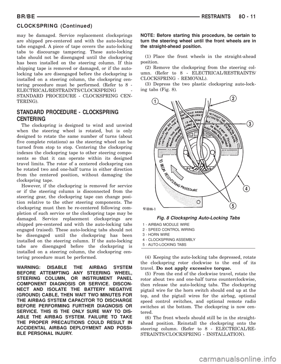
(3) Depress the two plastic clockspring auto-lock-
ing tabs (Fig. 8).
(4) Keeping the auto-locking tabs depressed, rotate
the clockspring rotor clockwise to the end of its
travel.Do not apply excessive torque.
(5) From the end of the clockwise travel, rotate the
rotor about two and one-half turns counterclockwise,
then release the auto-locking tabs. The clockspring
pigtail wire for the horn switch should end up at the
top, and the pigtail wires for the airbag, optional
speed control switches, and optional remote radio
switches at the bottom. The clockspring is now cen-
tered.
(6) The front wheels should still be in the straight-
ahead position. Reinstall the clockspring onto the
steering column. (Refer to 8 - ELECTRICAL/RE-
STRAINTS/CLOCKSPRING - INSTALLATION).
Fig. 8 Clockspring Auto-Locking Tabs
1 - AIRBAG MODULE WIRE
2 - SPEED CONTROL WIRING
3 - HORN WIRE
4 - CLOCKSPRING ASSEMBLY
5 - AUTO-LOCKING TABS
BR/BERESTRAINTS 8O - 11
CLOCKSPRING (Continued)
Page 605 of 2255
REMOVAL
The clockspring cannot be repaired. It must be
replaced if faulty or damaged, or if the driver airbag
has been deployed.
WARNING: DISABLE THE AIRBAG SYSTEM
BEFORE ATTEMPTING ANY STEERING WHEEL,
STEERING COLUMN, OR INSTRUMENT PANEL
COMPONENT DIAGNOSIS OR SERVICE. DISCON-
NECT AND ISOLATE THE BATTERY NEGATIVE
(GROUND) CABLE, THEN WAIT TWO MINUTES FOR
THE AIRBAG SYSTEM CAPACITOR TO DISCHARGE
BEFORE PERFORMING FURTHER DIAGNOSIS OR
SERVICE. THIS IS THE ONLY SURE WAY TO DIS-
ABLE THE AIRBAG SYSTEM. FAILURE TO TAKE
THE PROPER PRECAUTIONS COULD RESULT IN
ACCIDENTAL AIRBAG DEPLOYMENT AND POSSI-
BLE PERSONAL INJURY.
NOTE: Before starting this procedure, be certain to
turn the steering wheel until the front wheels are in
the straight-ahead position.
(1) Place the front wheels in the straight-ahead
position.
(2) Remove the driver airbag from the steering
wheel. (Refer to 8 - ELECTRICAL/RESTRAINTS/
DRIVER AIRBAG - REMOVAL).
(3) If the vehicle is so equipped, disconnect the
clockspring pigtail wire connectors from the speed
control switches and the remote radio switches
located within the hub cavity of the steering wheel.
(4) Remove the nut that secures the steering wheel
armature to the steering column upper shaft, which
is located within the hub cavity of the steering wheel.
(5) Pull the steering wheel off of the steering col-
umn upper shaft spline using a steering wheel puller
(Special Tool C-3428-B).
(6) Remove the steering column opening cover
from the instrument panel. (Refer to 23 - BODY/IN-
STRUMENT PANEL/STEERING COLUMN OPEN-
ING COVER - REMOVAL).
(7) If the vehicle is so equipped, unscrew the lever
from the tilt steering column adjuster mechanism
located on the left side of the column just below the
multi-function switch control stalk. Turn the lever
counterclockwise to unscrew it from the adjuster.
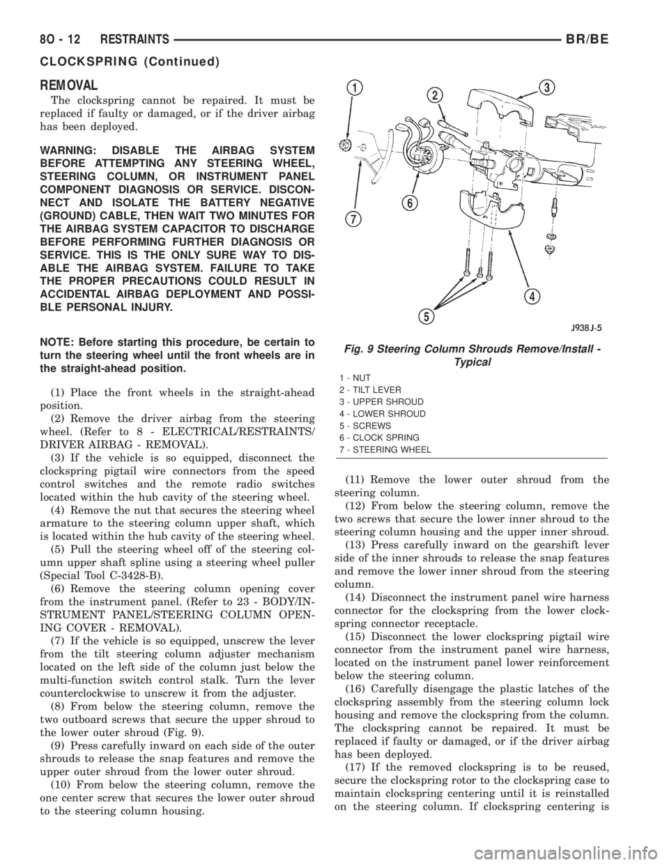
(8) From below the steering column, remove the
two outboard screws that secure the upper shroud to
the lower outer shroud (Fig. 9).
(9) Press carefully inward on each side of the outer
shrouds to release the snap features and remove the
upper outer shroud from the lower outer shroud.
(10) From below the steering column, remove the
one center screw that secures the lower outer shroud
to the steering column housing.(11) Remove the lower outer shroud from the
steering column.
(12) From below the steering column, remove the
two screws that secure the lower inner shroud to the
steering column housing and the upper inner shroud.
(13) Press carefully inward on the gearshift lever
side of the inner shrouds to release the snap features
and remove the lower inner shroud from the steering
column.
(14) Disconnect the instrument panel wire harness
connector for the clockspring from the lower clock-
spring connector receptacle.
(15) Disconnect the lower clockspring pigtail wire
connector from the instrument panel wire harness,
located on the instrument panel lower reinforcement
below the steering column.
(16) Carefully disengage the plastic latches of the
clockspring assembly from the steering column lock
housing and remove the clockspring from the column.
The clockspring cannot be repaired. It must be
replaced if faulty or damaged, or if the driver airbag
has been deployed.
(17) If the removed clockspring is to be reused,
secure the clockspring rotor to the clockspring case to
maintain clockspring centering until it is reinstalled
on the steering column. If clockspring centering is
Fig. 9 Steering Column Shrouds Remove/Install -
Typical
1 - NUT
2 - TILT LEVER
3 - UPPER SHROUD
4 - LOWER SHROUD
5 - SCREWS
6 - CLOCK SPRING
7 - STEERING WHEEL
8O - 12 RESTRAINTSBR/BE
CLOCKSPRING (Continued)
Page 606 of 2255
not maintained, the clockspring must be centered
again before it is reinstalled. (Refer to 8 - ELECTRI-
CAL/RESTRAINTS/CLOCKSPRING - STANDARD
PROCEDURE - CLOCKSPRING CENTERING).
INSTALLATION
The clockspring cannot be repaired. It must be
replaced if faulty or damaged, or if the driver airbag
has been deployed.
If the clockspring is not properly centered in rela-
tion to the steering wheel, steering shaft and steer-
ing gear, it may be damaged. (Refer to 8 -
ELECTRICAL/RESTRAINTS/CLOCKSPRING -
STANDARD PROCEDURE - CLOCKSPRING CEN-
TERING). Service replacement clocksprings are
shipped pre-centered and with a piece of tape cover-
ing the engaged clockspring auto-locking tabs. This
tape should not be removed until the clockspring has
been installed on the steering column. If the tape is
removed before the clockspring is installed on a
steering column, the clockspring centering procedure
must be performed.
WARNING: DISABLE THE AIRBAG SYSTEM
BEFORE ATTEMPTING ANY STEERING WHEEL,
STEERING COLUMN, OR INSTRUMENT PANEL
COMPONENT DIAGNOSIS OR SERVICE. DISCON-
NECT AND ISOLATE THE BATTERY NEGATIVE
(GROUND) CABLE, THEN WAIT TWO MINUTES FOR
THE AIRBAG SYSTEM CAPACITOR TO DISCHARGE
BEFORE PERFORMING FURTHER DIAGNOSIS OR
SERVICE. THIS IS THE ONLY SURE WAY TO DIS-
ABLE THE AIRBAG SYSTEM. FAILURE TO TAKE
THE PROPER PRECAUTIONS COULD RESULT IN
ACCIDENTAL AIRBAG DEPLOYMENT AND POSSI-
BLE PERSONAL INJURY.
NOTE: Before starting this procedure, be certain
that the front wheels are still in the straight-ahead
position.
(1) Carefully slide the centered clockspring down
over the steering column upper shaft until the clock-
spring latches engage the steering column lock hous-
ing (Fig. 9).
(2) Reconnect the lower clockspring pigtail wire
connector to the instrument panel wire harness con-
nector located near the instrument panel lower rein-
forcement, below the steering column. Be certain that
the pigtail wire locator clips are properly seated on
the outside of the wiring trough and that the connec-
tor latches are fully engaged.
(3) Reconnect the instrument panel wire harness
connector for the clockspring to the lower clockspring
connector receptacle.(4) Position the lower inner shroud onto the steer-
ing column. Be certain to insert the gearshift lever
hider strip into the channel located on the inside sur-
face of the shroud.
(5) Align the locking tabs on the gearshift lever
side of the upper inner shroud with the receptacles
on the lower inner shroud and apply hand pressure
to snap them together.
(6) From below the steering column, install and
tighten the two screws that secure the lower inner
shroud to the steering column housing and the upper
inner shroud. Tighten the screws to 2 N´m (18 in.
lbs.).
(7) Position the lower outer shroud onto the steer-
ing column. Be certain that the lower clockspring
pigtail wire is routed inside the shrouds.
(8) From below the steering column, install and
tighten the one center screw that secures the lower
outer shroud to the steering column housing. Tighten
the screw to 2 N´m (18 in. lbs.).
(9) Align the locking tabs on the upper outer
shroud with the receptacles on the lower outer
shroud and apply hand pressure to snap them
together.
(10) From below the steering column, install and
tighten the two outboard screws that secure the
lower outer shroud to the upper outer shroud.
Tighten the screws to 2 N´m (18 in. lbs.).
(11) If the vehicle is so equipped, reinstall the
lever into the tilt steering column adjuster on the left
side of the column. Turn the lever clockwise to screw
it into the adjuster.
(12) Reinstall the steering column opening cover
onto the instrument panel. (Refer to 23 - BODY/IN-
STRUMENT PANEL/STEERING COLUMN OPEN-
ING COVER - INSTALLATION).
(13) Reinstall the steering wheel onto the steering
column upper shaft. Be certain to index the flats on
the hub of the steering wheel with the formations on
the inside of the clockspring hub. Pull the upper
clockspring pigtail wires through the upper and
lower holes between the steering wheel back trim
cover and the steering wheel armature.
(14) Install and tighten the steering wheel mount-
ing nut. Tighten the nut to 61 N´m (45 ft. lbs.). Be
certain not to pinch the pigtail wires between the
steering wheel and the nut.
(15) If the vehicle is so equipped, reconnect the
upper clockspring pigtail wire connectors to the
speed control switches and/or the remote radio
switches. Be certain that the upper clockspring pig-
tail wires are routed between the steering wheel back
trim cover and the steering wheel armature.
(16) Reinstall the driver airbag onto the steering
wheel. (Refer to 8 - ELECTRICAL/RESTRAINTS/
DRIVER AIRBAG - INSTALLATION).
BR/BERESTRAINTS 8O - 13
CLOCKSPRING (Continued)
Page 635 of 2255
(4) Insert servo studs through holes in servo cable
sleeve.
(5) Install servo mounting nuts and tighten to 8.5
N´m (75 in. lbs.) torque.
(6) Connect vacuum line to servo.
(7) Connect electrical connector to servo terminals.
(8) Connect servo cable to throttle body. Refer to
Servo Cable Removal/Installation in this group.
(9) Install battery tray. Tighten all battery tray
mounting hardware to 16 N´m (140 in. lbs.) torque.
(10) Position battery into battery tray.
(11) If equipped, install battery heat shield.
(12) Install battery holddown clamp. Tighten bolt
to 4 N´m (35 in. lbs.) torque.
(13) Connect positive battery cable to battery.
(14) Connect negative battery cable to battery.
(15) Before starting engine, operate accelerator
pedal to check for any binding.
INSTALLATION - DIESEL WITH AUTO. TRANS.
(1) Position servo to mounting bracket.
(2) Align hole in cable connector with hole in servo
pin. Install cable-to-servo retaining clip.
(3) Insert servo studs through holes in servo
mounting bracket.
(4) Insert servo studs through holes in servo cable
sleeve.
(5) Install servo mounting nuts and tighten to 8.5
N´m (75 in. lbs.) torque.
(6) Connect vacuum line to servo.
(7) Connect electrical connector to servo terminals.
(8) Connect servo cable to throttle lever by push-
ing cable connector rearward onto lever pin while
holding lever forward.
(9) Install battery tray. Tighten all battery tray
mounting hardware to 16 N´m (140 in. lbs.) torque.
(10) Position battery into battery tray.
(11) If equipped, install battery heat shield.
(12) Install battery holddown clamp. Tighten bolt
to 4 N´m (35 in. lbs.) torque.
(13) Connect positive battery cable to battery.
(14) Connect negative battery cables to both bat-
teries.
(15) Before starting engine, operate accelerator
pedal to check for any binding.
(16) Install cable/lever cover.
SWITCH
DESCRIPTION
Gas Engines and Diesel With Auto. Trans.
There are two separate switch pods that operate
the speed control system. The steering-wheel-
mounted switches use multiplexed circuits to provideinputs to the Powertrain Control Module (PCM) for
ON, OFF, RESUME, ACCELERATE, SET, DECEL
and CANCEL modes. Refer to the owner's manual for
more information on speed control switch functions
and setting procedures.
The individual switches cannot be repaired. If one
switch fails, the entire switch module must be
replaced.
Diesel With Manual Trans.
There are two separate switch pods that operate
the speed control system. The steering-wheel-
mounted switches use multiplexed circuits to provide
inputs to the Engine Control Module (ECM) for ON,
OFF, RESUME, ACCELERATE, SET, DECEL and
CANCEL modes. Refer to the owner's manual for
more information on speed control switch functions
and setting procedures.
The individual switches cannot be repaired. If one
switch fails, the entire switch module must be
replaced.
OPERATION
Gas Engines and Diesel With Auto. Trans.
When speed control is selected by depressing the
ON, OFF switch, the Powertrain Control Module
(PCM) allows a set speed to be stored in its RAM for
speed control. To store a set speed, depress the SET
switch while the vehicle is moving at a speed
between approximately 35 and 85 mph. In order for
the speed control to engage, the brakes cannot be
applied, nor can the gear selector be indicating the
transmission is in Park or Neutral.
The speed control can be disengaged manually by:
²Stepping on the brake pedal.
²Depressing the OFF switch.
²Depressing the CANCEL switch.
The speed control can be disengaged also by any of
the following conditions:
²An indication of Park or Neutral.
²The vehicle speed signal increases at a rate of
10 mph per second (indicates that the co-efficient of
friction between the road surface and tires is
extremely low).
²Depressing the clutch pedal.
²Excessive engine rpm (indicates that the trans-
mission may be in a low gear).
²The vehicle speed signal decreases at a rate of
10 mph per second (indicates that the vehicle may
have decelerated at an extremely high rate).
²If the actual speed is not within 20 mph of the
set speed.
The previous disengagement conditions are pro-
grammed for added safety.
8P - 12 SPEED CONTROLBR/BE
SPEED CONTROL SERVO (Continued)
Page 636 of 2255
Once the speed control has been disengaged,
depressing the ACCEL switch restores the vehicle to
the target speed that was stored in the PCM's RAM.
NOTE: Depressing the OFF switch will erase the set
speed stored in the PCM's RAM.
If, while the speed control is engaged, the driver
wishes to increase vehicle speed, the PCM is pro-
grammed for an acceleration feature. With the
ACCEL switch held closed, the vehicle accelerates
slowly to the desired speed. The new target speed is
stored in the PCM's RAM when the ACCEL switch is
released. The PCM also has a9tap-up9feature in
which vehicle speed increases at a rate of approxi-
mately 2 mph for each momentary switch activation
of the ACCEL switch.
The PCM also provides a means to decelerate with-
out disengaging speed control. To decelerate from an
existing recorded target speed, depress and hold the
COAST switch until the desired speed is reached.
Then release the switch. The ON, OFF switch oper-
ates two components: the PCM's ON, OFF input, and
the battery voltage to the brake switch, which powers
the speed control servo.
Diesel With Manual Trans.
When speed control is selected by depressing the
ON, OFF switch, the Engine Control Module (ECM)
allows a set speed to be stored in its RAM for speed
control. To store a set speed, depress the SET switch
while the vehicle is moving at a speed between
approximately 35 and 85 mph. In order for the speed
control to engage, the brakes cannot be applied.
The speed control can be disengaged manually by:
²Stepping on the brake pedal.
²Depressing the OFF switch.
²Depressing the CANCEL switch.
The speed control can be disengaged also by any of
the following conditions:
²The vehicle speed signal increases at a rate of
10 mph per second (indicates that the co-efficient of
friction between the road surface and tires is
extremely low).
²Depressing the clutch pedal.
²Excessive engine rpm (indicates that the trans-
mission may be in a low gear).
²The vehicle speed signal decreases at a rate of
10 mph per second (indicates that the vehicle may
have decelerated at an extremely high rate).
²If the actual speed is not within 20 mph of the
set speed.The previous disengagement conditions are pro-
grammed for added safety.
Once the speed control has been disengaged,
depressing the ACCEL switch restores the vehicle to
the target speed that was stored in the ECM's RAM.
NOTE: Depressing the OFF switch will erase the set
speed stored in the ECM's RAM.
If, while the speed control is engaged, the driver
wishes to increase vehicle speed, the ECM is pro-
grammed for an acceleration feature. With the
ACCEL switch held closed, the vehicle accelerates
slowly to the desired speed. The new target speed is
stored in the ECM's RAM when the ACCEL switch is
released. The ECM also has a9tap-up9feature in
which vehicle speed increases at a rate of approxi-
mately 2 mph for each momentary switch activation
of the ACCEL switch.
The ECM also provides a means to decelerate with-
out disengaging speed control. To decelerate from an
existing recorded target speed, depress and hold the
COAST switch until the desired speed is reached.
Then release the switch. The ON, OFF switch oper-
ates two components: the ECM's ON, OFF input, and
the battery voltage to the brake switch, which powers
the speed control servo.
REMOVAL
WARNING: BEFORE BEGINNING ANY AIRBAG SYS-
TEM COMPONENT REMOVAL OR INSTALLATION,
REMOVE AND ISOLATE THE NEGATIVE (-)
CABLE(S) FROM THE BATTERY. THIS IS THE ONLY
SURE WAY TO DISABLE THE AIRBAG SYSTEM.
THEN WAIT TWO MINUTES FOR SYSTEM CAPACI-
TOR TO DISCHARGE BEFORE FURTHER SYSTEM
SERVICE. FAILURE TO DO THIS COULD RESULT IN
ACCIDENTAL AIRBAG DEPLOYMENT AND POSSI-
BLE INJURY.
(1) Disconnect and isolate negative battery
cable(s).
(2) Remove airbag module. Refer to 8, Restraint
Systems for procedures.
(3) Remove switch-to-steering wheel mounting
screws (Fig. 20).
(4) Remove switch.
(5) Remove electrical connector at switch.
BR/BESPEED CONTROL 8P - 13
SWITCH (Continued)
Page 1410 of 2255
STEERING
TABLE OF CONTENTS
page page
STEERING
DESCRIPTION..........................1
OPERATION............................1
DIAGNOSIS AND TESTING
DIAGNOSIS AND TESTING - POWER
STEERING SYSTEM....................2
DIAGNOSIS AND TESTING - POWER
STEERING FLOW AND PRESSURE........4COLUMN...............................6
GEAR.................................16
PUMP.................................33
LINKAGE - 2WD.........................40
LINKAGE - 4WD.........................42
STEERING
DESCRIPTION
The power steering system consist of a steering col-
umn, steering gear and hydraulic pump. The gear is
mounted to the frame rail and attaches to the steer-
ing linkage. The pump is a constant flow rate and
displacement vane-type pump. The pump supplies
hydraulic fluid pressure to the power steering gear
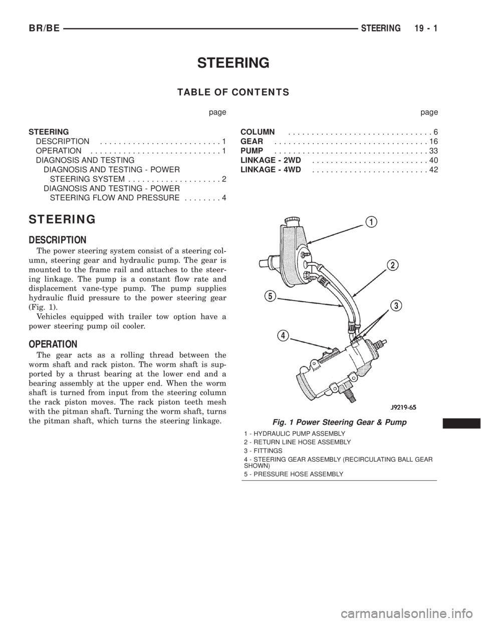
(Fig. 1).
Vehicles equipped with trailer tow option have a
power steering pump oil cooler.
OPERATION
The gear acts as a rolling thread between the
worm shaft and rack piston. The worm shaft is sup-
ported by a thrust bearing at the lower end and a
bearing assembly at the upper end. When the worm
shaft is turned from input from the steering column
the rack piston moves. The rack piston teeth mesh
with the pitman shaft. Turning the worm shaft, turns
the pitman shaft, which turns the steering linkage.
Fig. 1 Power Steering Gear & Pump
1 - HYDRAULIC PUMP ASSEMBLY
2 - RETURN LINE HOSE ASSEMBLY
3 - FITTINGS
4 - STEERING GEAR ASSEMBLY (RECIRCULATING BALL GEAR
SHOWN)
5 - PRESSURE HOSE ASSEMBLY
BR/BESTEERING 19 - 1
Page 1411 of 2255
DIAGNOSIS AND TESTING
DIAGNOSIS AND TESTING - POWER STEERING SYSTEM
STEERING NOISE
There is some noise in all power steering systems. One of the most common is a hissing sound evident at a
standstill parking. Or when the steering wheel is at the end of it's travel. Hiss is a high frequency noise similar
to that of a water tap being closed slowly. The noise is present in all valves that have a high velocity fluid passing
through an orifice. There is no relationship between this noise and steering performance.
CONDITION POSSIBLE CAUSES CORRECTION
OBJECTIONAL HISS OR
WHISTLE1. Steering intermediate shaft to dash panel
seal.1. Check and repair seal at dash
panel.
2. Noisy valve in power steering gear. 2. Repair steering gear.
RATTLE OR CLUNK 1. Gear mounting bolts loose. 1. Tighten bolts to specification.
2. Loose or damaged suspension
components.2. Inspect and repair suspension.
3. Loose or damaged steering linkage. 3. Inspect and repair steering
linkage.
4. Internal gear noise. 4. Repair steering gear.
5. Pressure hose in contact with other
components.5. Reposition hose.
6. Loose or damaged intermediate shaft or
column.6. Inspect and repair or replace.
CHIRP OR SQUEAL 1. Loose belt. 1. Adjust or replace.
WHINE OR GROWL 1. Low fluid level. 1. Fill to proper level.
2. Pressure hose in contact with other
components.2. Reposition hose.
3. Internal pump noise. 3. Replace pump.
SUCKING AIR SOUND 1. Loose return line clamp. 1. Replace clamp.
2. O-ring missing or damaged on hose
fitting.2. Replace o-ring.
3. Low fluid level. 3. Fill to proper level.
4. Air leak between pump and reservoir. 4. Repair as necessary.
5. Reservoir cap not installed correctly. 5. Install reservoir cap correctly.
SCRUBBING OR
KNOCKING1. Wrong tire size. 1. Verify tire size.
2. Wrong gear. 2. Verify gear.
19 - 2 STEERINGBR/BE
STEERING (Continued)
Page 1412 of 2255
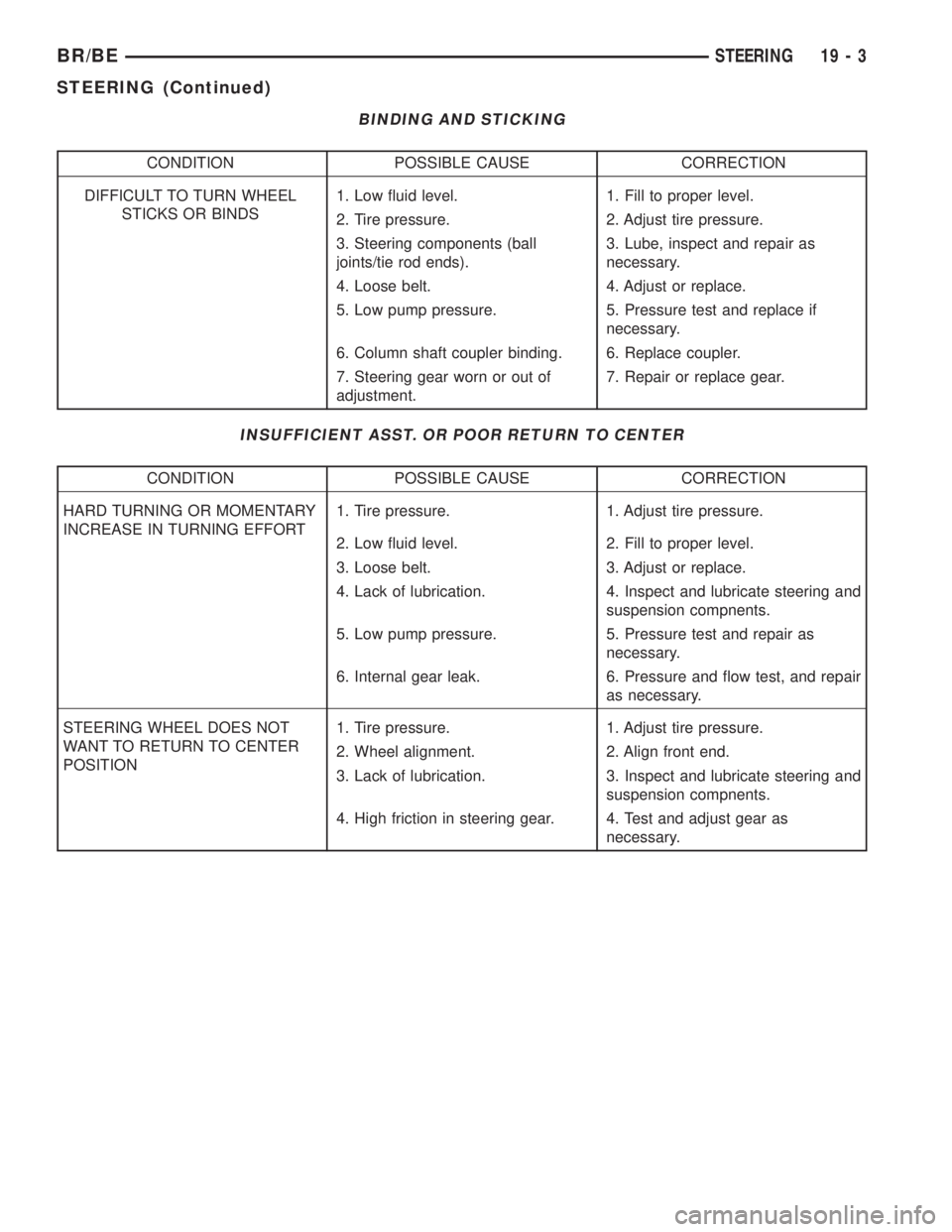
BINDING AND STICKING
CONDITION POSSIBLE CAUSE CORRECTION
DIFFICULT TO TURN WHEEL
STICKS OR BINDS1. Low fluid level. 1. Fill to proper level.
2. Tire pressure. 2. Adjust tire pressure.
3. Steering components (ball
joints/tie rod ends).3. Lube, inspect and repair as
necessary.
4. Loose belt. 4. Adjust or replace.
5. Low pump pressure. 5. Pressure test and replace if
necessary.
6. Column shaft coupler binding. 6. Replace coupler.
7. Steering gear worn or out of
adjustment.7. Repair or replace gear.
INSUFFICIENT ASST. OR POOR RETURN TO CENTER
CONDITION POSSIBLE CAUSE CORRECTION
HARD TURNING OR MOMENTARY
INCREASE IN TURNING EFFORT1. Tire pressure. 1. Adjust tire pressure.
2. Low fluid level. 2. Fill to proper level.
3. Loose belt. 3. Adjust or replace.
4. Lack of lubrication. 4. Inspect and lubricate steering and
suspension compnents.
5. Low pump pressure. 5. Pressure test and repair as
necessary.
6. Internal gear leak. 6. Pressure and flow test, and repair
as necessary.
STEERING WHEEL DOES NOT
WANT TO RETURN TO CENTER
POSITION1. Tire pressure. 1. Adjust tire pressure.
2. Wheel alignment. 2. Align front end.
3. Lack of lubrication. 3. Inspect and lubricate steering and
suspension compnents.
4. High friction in steering gear. 4. Test and adjust gear as
necessary.
BR/BESTEERING 19 - 3
STEERING (Continued)
Page 1413 of 2255
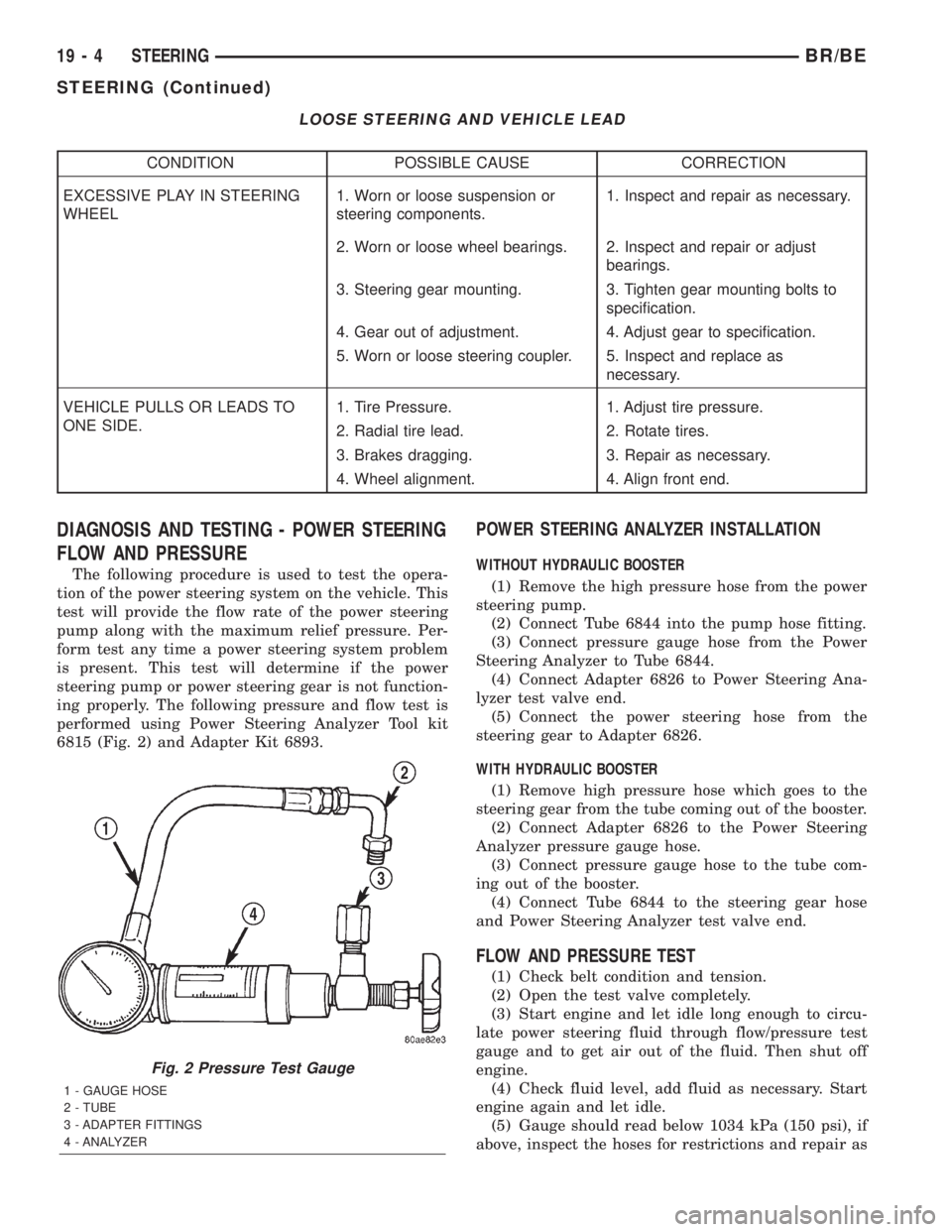
LOOSE STEERING AND VEHICLE LEAD
CONDITION POSSIBLE CAUSE CORRECTION
EXCESSIVE PLAY IN STEERING
WHEEL1. Worn or loose suspension or
steering components.1. Inspect and repair as necessary.
2. Worn or loose wheel bearings. 2. Inspect and repair or adjust
bearings.
3. Steering gear mounting. 3. Tighten gear mounting bolts to
specification.
4. Gear out of adjustment. 4. Adjust gear to specification.
5. Worn or loose steering coupler. 5. Inspect and replace as
necessary.
VEHICLE PULLS OR LEADS TO
ONE SIDE.1. Tire Pressure. 1. Adjust tire pressure.
2. Radial tire lead. 2. Rotate tires.
3. Brakes dragging. 3. Repair as necessary.
4. Wheel alignment. 4. Align front end.
DIAGNOSIS AND TESTING - POWER STEERING
FLOW AND PRESSURE
The following procedure is used to test the opera-
tion of the power steering system on the vehicle. This
test will provide the flow rate of the power steering
pump along with the maximum relief pressure. Per-
form test any time a power steering system problem
is present. This test will determine if the power
steering pump or power steering gear is not function-
ing properly. The following pressure and flow test is
performed using Power Steering Analyzer Tool kit
6815 (Fig. 2) and Adapter Kit 6893.
POWER STEERING ANALYZER INSTALLATION
WITHOUT HYDRAULIC BOOSTER
(1) Remove the high pressure hose from the power
steering pump.
(2) Connect Tube 6844 into the pump hose fitting.
(3) Connect pressure gauge hose from the Power
Steering Analyzer to Tube 6844.
(4) Connect Adapter 6826 to Power Steering Ana-
lyzer test valve end.
(5) Connect the power steering hose from the
steering gear to Adapter 6826.
WITH HYDRAULIC BOOSTER
(1) Remove high pressure hose which goes to the
steering gear from the tube coming out of the booster.
(2) Connect Adapter 6826 to the Power Steering
Analyzer pressure gauge hose.
(3) Connect pressure gauge hose to the tube com-
ing out of the booster.
(4) Connect Tube 6844 to the steering gear hose
and Power Steering Analyzer test valve end.
FLOW AND PRESSURE TEST
(1) Check belt condition and tension.
(2) Open the test valve completely.
(3) Start engine and let idle long enough to circu-
late power steering fluid through flow/pressure test
gauge and to get air out of the fluid. Then shut off
engine.
(4) Check fluid level, add fluid as necessary. Start
engine again and let idle.
(5) Gauge should read below 1034 kPa (150 psi), if
above, inspect the hoses for restrictions and repair as
Fig. 2 Pressure Test Gauge
1 - GAUGE HOSE
2 - TUBE
3 - ADAPTER FITTINGS
4 - ANALYZER
19 - 4 STEERINGBR/BE
STEERING (Continued)