check transmission fluid DODGE RAM 2002 Service Repair Manual
[x] Cancel search | Manufacturer: DODGE, Model Year: 2002, Model line: RAM, Model: DODGE RAM 2002Pages: 2255, PDF Size: 62.07 MB
Page 19 of 2255
DESCRIPTION - AUTOMATIC TRANSMISSION
FLUID
NOTE: Refer to the maintenance schedules in this
group for the recommended maintenance (fluid/filter
change) intervals for this transmission.
NOTE: Refer to Service Procedures in this group for
fluid level checking procedures.
MopartATF +4, type 9602, Automatic Transmis-
sion Fluid is the recommended fluid for
DaimlerChrysler automatic transmissions.
Dexron II fluid IS NOT recommended. Clutch
chatter can result from the use of improper
fluid.
MopartATF +4, type 9602, Automatic Transmis-
sion Fluid when new is red in color. The ATF is dyed
red so it can be identified from other fluids used in
the vehicle such as engine oil or antifreeze. The red
color is not permanent and is not an indicator of fluid
condition. As the vehicle is driven, the ATF will begin
to look darker in color and may eventually become
brown.This is normal.A dark brown/black fluid
accompanied with a burnt odor and/or deterioration
in shift quality may indicate fluid deterioration or
transmission component failure.
FLUID ADDITIVES
DaimlerChrysler strongly recommends against the
addition of any fluids to the transmission, other than
those automatic transmission fluids listed above.
Exceptions to this policy are the use of special dyes
to aid in detecting fluid leaks.
Various ªspecialº additives and supplements exist
that claim to improve shift feel and/or quality. These
additives and others also claim to improve converter
clutch operation and inhibit overheating, oxidation,
varnish, and sludge. These claims have not been sup-
ported to the satisfaction of DaimlerChrysler and
these additivesmust not be used.The use of trans-
mission ªsealersº should also be avoided, since they
may adversely affect the integrity of transmission
seals.
OPERATION - AUTOMATIC TRANSMISSION
FLUID
The automatic transmission fluid is selected based
upon several qualities. The fluid must provide a high
level of protection for the internal components by
providing a lubricating film between adjacent metal
components. The fluid must also be thermally stable
so that it can maintain a consistent viscosity through
a large temperature range. If the viscosity stays con-
stant through the temperature range of operation,transmission operation and shift feel will remain con-
sistent. Transmission fluid must also be a good con-
ductor of heat. The fluid must absorb heat from the
internal transmission components and transfer that
heat to the transmission case.
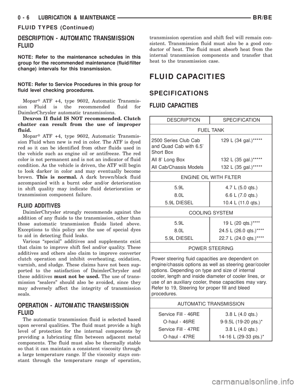
FLUID CAPACITIES
SPECIFICATIONS
FLUID CAPACITIES
DESCRIPTION SPECIFICATION
FUEL TANK
2500 Series Club Cab
and Quad Cab with 6.5'
Short Box129 L (34 gal.)*****
All 8' Long Box 132 L (35 gal.)*****
All Cab/Chassis Models 132 L (35 gal.)*****
ENGINE OIL WITH FILTER
5.9L 4.7 L (5.0 qts.)
8.0L 6.6 L (7.0 qts.)
5.9L DIESEL 10.4 L (11.0 qts.)
COOLING SYSTEM
5.9L 19 L (20 qts.)****
8.0L 24.5 L (26.0 qts.)****
5.9L DIESEL 22.7 L (24.0 qts.)****
POWER STEERING
Power steering fluid capacities are dependent on
engine/chassis options as well as steering gear/cooler
options. Depending on type and size of internal
cooler, length and inside diameter of cooler lines, or
use of an auxiliary cooler, these capacities may vary.
Refer to 19, Steering for proper fill and bleed
procedures.
AUTOMATIC TRANSMISSION
Service Fill - 46RE 3.8 L (4.0 qts.)
O-haul - 46RE 9-9.5L (19-20 pts.)*
Service Fill - 47RE 3.8 L (4.0 qts.)
O-haul - 47RE 14-16 L (29-33 pts.)*
0 - 6 LUBRICATION & MAINTENANCEBR/BE
FLUID TYPES (Continued)
Page 135 of 2255
torque supplied to the non-slipping wheel. The differ-
ential resist wheel spin on bumpy roads and provide
more pulling power when one wheel looses traction.
Pulling power is provided continuously until both
wheels loose traction. If both wheels slip due to
unequal traction, operation is normal. In extreme
cases of differences of traction, the wheel with the
least traction may spin.
DIAGNOSIS AND TESTING - AXLE
GEAR NOISE
Axle gear noise can be caused by insufficient lubri-
cant, incorrect backlash, incorrect pinion depth, tooth
contact, worn/damaged gears, or the carrier housing
not having the proper offset and squareness.
Gear noise usually happens at a specific speed
range. The noise can also occur during a specific type
of driving condition. These conditions are accelera-
tion, deceleration, coast, or constant load.
When road testing, first warm-up the axle fluid by
driving the vehicle at least 5 miles and then acceler-
ate the vehicle to the speed range where the noise is
the greatest. Shift out-of-gear and coast through the
peak-noise range. If the noise stops or changes
greatly:
²Check for insufficient lubricant.
²Incorrect ring gear backlash.
²Gear damage.
Differential side gears and pinions can be checked
by turning the vehicle. They usually do not cause
noise during straight-ahead driving when the gears
are unloaded. The side gears are loaded during vehi-
cle turns. A worn pinion shaft can also cause a snap-
ping or a knocking noise.
BEARING NOISE
The axle shaft, differential and pinion bearings can
all produce noise when worn or damaged. Bearing
noise can be either a whining, or a growling sound.
Pinion bearings have a constant-pitch noise. This
noise changes only with vehicle speed. Pinion bearing
noise will be higher pitched because it rotates at a
faster rate. Drive the vehicle and load the differen-
tial. If bearing noise occurs, the rear pinion bearing
is the source of the noise. If the bearing noise is
heard during a coast, the front pinion bearing is the
source.
Worn or damaged differential bearings usually pro-
duce a low pitch noise. Differential bearing noise is
similar to pinion bearing noise. The pitch of differen-
tial bearing noise is also constant and varies only
with vehicle speed.Axle shaft bearings produce noise and vibration
when worn or damaged. The noise generally changes
when the bearings are loaded. Road test the vehicle.
Turn the vehicle sharply to the left and to the right.
This will load the bearings and change the noise
level. Where axle bearing damage is slight, the noise
is usually not noticeable at speeds above 30 mph.
LOW SPEED KNOCK
Low speed knock is generally caused by a worn
U-joint or by worn side±gear thrust washers. A worn
pinion shaft bore will also cause low speed knock.
VIBRATION
Vibration at the rear of the vehicle is usually
caused by a:
²Damaged drive shaft.
²Missing drive shaft balance weight(s).
²Worn or out-of-balance wheels.
²Loose wheel lug nuts.
²Worn U-joint(s).
²Loose/broken springs.
²Damaged axle shaft bearing(s).
²Loose pinion gear nut.
²Excessive pinion yoke run out.
²Bent axle shaft(s).
Check for loose or damaged front-end components
or engine/transmission mounts. These components
can contribute to what appears to be a rearend vibra-
tion. Do not overlook engine accessories, brackets
and drive belts.
NOTE: All driveline components should be exam-
ined before starting any repair.
DRIVELINE SNAP
A snap or clunk noise when the vehicle is shifted
into gear (or the clutch engaged), can be caused by:
²High engine idle speed.
²Transmission shift operation.
²Loose engine/transmission/transfer case mounts.
²Worn U-joints.
²Loose spring mounts.
²Loose pinion gear nut and yoke.
²Excessive ring gear backlash.
²Excessive side gear to case clearance.
The source of a snap or a clunk noise can be deter-
mined with the assistance of a helper. Raise the vehi-
cle on a hoist with the wheels free to rotate. Instruct
the helper to shift the transmission into gear. Listen
for the noise, a mechanics stethoscope is helpful in
isolating the source of a noise.
3 - 80 REAR AXLE - 267RBIBR/BE
REAR AXLE - 267RBI (Continued)
Page 163 of 2255
OPERATION
STANDARD DIFFERENTIAL
The axle receives power from the transmission/
transfer case through the rear propeller shaft. The
rear propeller shaft is connected to the pinion gear
which rotates the differential through the gear mesh
with the ring gear bolted to the differential case. The
engine power is transmitted to the axle shafts
through the pinion mate and side gears. The side
gears are splined to the axle shafts.
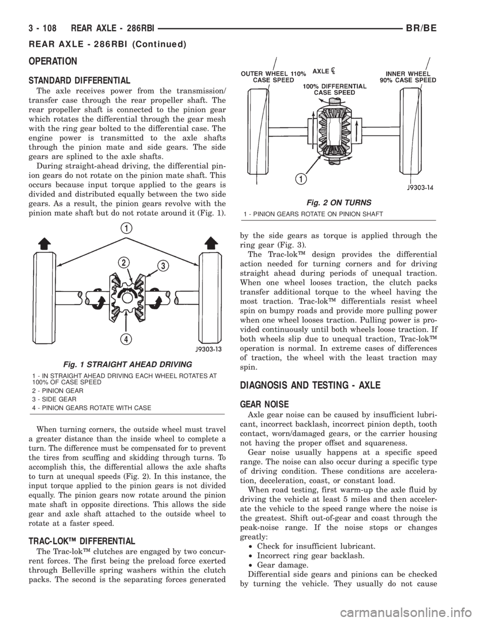
During straight-ahead driving, the differential pin-
ion gears do not rotate on the pinion mate shaft. This
occurs because input torque applied to the gears is
divided and distributed equally between the two side
gears. As a result, the pinion gears revolve with the
pinion mate shaft but do not rotate around it (Fig. 1).
When turning corners, the outside wheel must travel
a greater distance than the inside wheel to complete a
turn. The difference must be compensated for to prevent
the tires from scuffing and skidding through turns. To
accomplish this, the differential allows the axle shafts
to turn at unequal speeds (Fig. 2). In this instance, the
input torque applied to the pinion gears is not divided
equally. The pinion gears now rotate around the pinion
mate shaft in opposite directions. This allows the side
gear and axle shaft attached to the outside wheel to
rotate at a faster speed.
TRAC-LOKŸ DIFFERENTIAL
The Trac-lokŸ clutches are engaged by two concur-
rent forces. The first being the preload force exerted
through Belleville spring washers within the clutch
packs. The second is the separating forces generatedby the side gears as torque is applied through the
ring gear (Fig. 3).
The Trac-lokŸ design provides the differential
action needed for turning corners and for driving
straight ahead during periods of unequal traction.
When one wheel looses traction, the clutch packs
transfer additional torque to the wheel having the
most traction. Trac-lokŸ differentials resist wheel
spin on bumpy roads and provide more pulling power
when one wheel looses traction. Pulling power is pro-
vided continuously until both wheels loose traction. If
both wheels slip due to unequal traction, Trac-lokŸ
operation is normal. In extreme cases of differences
of traction, the wheel with the least traction may
spin.
DIAGNOSIS AND TESTING - AXLE
GEAR NOISE
Axle gear noise can be caused by insufficient lubri-
cant, incorrect backlash, incorrect pinion depth, tooth
contact, worn/damaged gears, or the carrier housing
not having the proper offset and squareness.
Gear noise usually happens at a specific speed
range. The noise can also occur during a specific type
of driving condition. These conditions are accelera-
tion, deceleration, coast, or constant load.
When road testing, first warm-up the axle fluid by
driving the vehicle at least 5 miles and then acceler-
ate the vehicle to the speed range where the noise is
the greatest. Shift out-of-gear and coast through the
peak-noise range. If the noise stops or changes
greatly:
²Check for insufficient lubricant.
²Incorrect ring gear backlash.
²Gear damage.
Differential side gears and pinions can be checked
by turning the vehicle. They usually do not cause
Fig. 1 STRAIGHT AHEAD DRIVING
1 - IN STRAIGHT AHEAD DRIVING EACH WHEEL ROTATES AT
100% OF CASE SPEED
2 - PINION GEAR
3 - SIDE GEAR
4 - PINION GEARS ROTATE WITH CASE
Fig. 2 ON TURNS
1 - PINION GEARS ROTATE ON PINION SHAFT
3 - 108 REAR AXLE - 286RBIBR/BE
REAR AXLE - 286RBI (Continued)
Page 194 of 2255
CAUTION: Never use gasoline, kerosene, alcohol,
motor oil, transmission fluid, or any fluid containing
mineral oil to clean the system components. These
fluids damage rubber cups and seals. Use only
fresh brake fluid or Mopar brake cleaner to clean or
flush brake system components. These are the only
cleaning materials recommended. If system contam-
ination is suspected, check the fluid for dirt, discol-
oration, or separation into distinct layers. Also
check the reservoir cap seal for distortion. Drain
and flush the system with new brake fluid if con-
tamination is suspected.
CAUTION: Use Mopar brake fluid, or an equivalent
quality fluid meeting SAE/DOT standards J1703 and
DOT 3. Brake fluid must be clean and free of con-
taminants. Use fresh fluid from sealed containers
only to ensure proper antilock component opera-
tion.
CAUTION: Use Mopar multi-mileage or high temper-
ature grease to lubricate caliper slide surfaces,
drum brake pivot pins, and shoe contact points on
the backing plates. Use multi-mileage grease or GE
661 or Dow 111 silicone grease on caliper slide pins
to ensure proper operation.
DIAGNOSIS AND TESTING - BASE BRAKE
SYSTEM
Base brake components consist of the brake shoes,
calipers, wheel cylinders, brake drums, rotors, brake
lines, master cylinder, booster, and parking brake
components.
Brake diagnosis involves determining if the prob-
lem is related to a mechanical, hydraulic, or vacuum
operated component.
The first diagnosis step is the preliminary check.
PRELIMINARY BRAKE CHECK
(1) Check condition of tires and wheels. Damaged
wheels and worn, damaged, or underinflated tires
can cause pull, shudder, vibration, and a condition
similar to grab.
(2) If complaint was based on noise when braking,
check suspension components. Jounce front and rear
of vehicle and listen for noise that might be caused
by loose, worn or damaged suspension or steering
components.
(3) Inspect brake fluid level and condition. Note
that the brake reservoir fluid level will decrease in
proportion to normal lining wear.Also note that
brake fluid tends to darken over time. This is
normal and should not be mistaken for contam-
ination.(a) If fluid level is abnormally low, look for evi-
dence of leaks at calipers, wheel cylinders, brake
lines, and master cylinder.
(b) If fluid appears contaminated, drain out a
sample to examine. System will have to be flushed
if fluid is separated into layers, or contains a sub-
stance other than brake fluid. The system seals
and cups will also have to be replaced after flush-
ing. Use clean brake fluid to flush the system.
(4) Check parking brake operation. Verify free
movement and full release of cables and pedal. Also
note if vehicle was being operated with parking
brake partially applied.
(5) Check brake pedal operation. Verify that pedal
does not bind and has adequate free play. If pedal
lacks free play, check pedal and power booster for
being loose or for bind condition. Do not road test
until condition is corrected.
(6) Check booster vacuum check valve and hose.
(7) If components checked appear OK, road test
the vehicle.
ROAD TESTING
(1) If complaint involved low brake pedal, pump
pedal and note if it comes back up to normal height.
(2) Check brake pedal response with transmission
in Neutral and engine running. Pedal should remain
firm under constant foot pressure.
(3) During road test, make normal and firm brake
stops in 25-40 mph range. Note faulty brake opera-
tion such as low pedal, hard pedal, fade, pedal pulsa-
tion, pull, grab, drag, noise, etc.
(4) Attempt to stop the vehicle with the parking
brake only and note grab, drag, noise, etc.
PEDAL FALLS AWAY
A brake pedal that falls away under steady foot
pressure is generally the result of a system leak. The
leak point could be at a brake line, fitting, hose, or
caliper/wheel cylinder. If leakage is severe, fluid will
be evident at or around the leaking component.
Internal leakage (seal by-pass) in the master cylin-
der caused by worn or damaged piston cups, may
also be the problem cause.
An internal leak in the ABS or RWAL system may
also be the problem with no physical evidence.
LOW PEDAL
If a low pedal is experienced, pump the pedal sev-
eral times. If the pedal comes back up, worn linings,
rotors, drums, or rear brakes out of adjustment are
the most likely causes. The proper course of action is
to inspect and replace all worn component and make
the proper adjustments.
BR/BEBRAKES - BASE 5 - 5
HYDRAULIC/MECHANICAL (Continued)
Page 204 of 2255
(8) Remove the supports and lower the vehicle.
(9) Verify a firm pedal before moving the vehicle.
FLUID
DIAGNOSIS AND TESTING - BRAKE FLUID
CONTAMINATION
Indications of fluid contamination are swollen or
deteriorated rubber parts.
Swollen rubber parts indicate the presence of
petroleum in the brake fluid.
To test for contamination, put a small amount of
drained brake fluid in clear glass jar. If fluid sepa-
rates into layers, there is mineral oil or other fluid
contamination of the brake fluid.
If brake fluid is contaminated, drain and thor-
oughly flush system. Replace master cylinder, propor-
tioning valve, caliper seals, wheel cylinder seals,
Antilock Brakes hydraulic unit and all hydraulic
fluid hoses.
STANDARD PROCEDURE - BRAKE FLUID
LEVEL
Always clean the master cylinder reservoir and
caps before checking fluid level. If not cleaned, dirt
could enter the fluid.
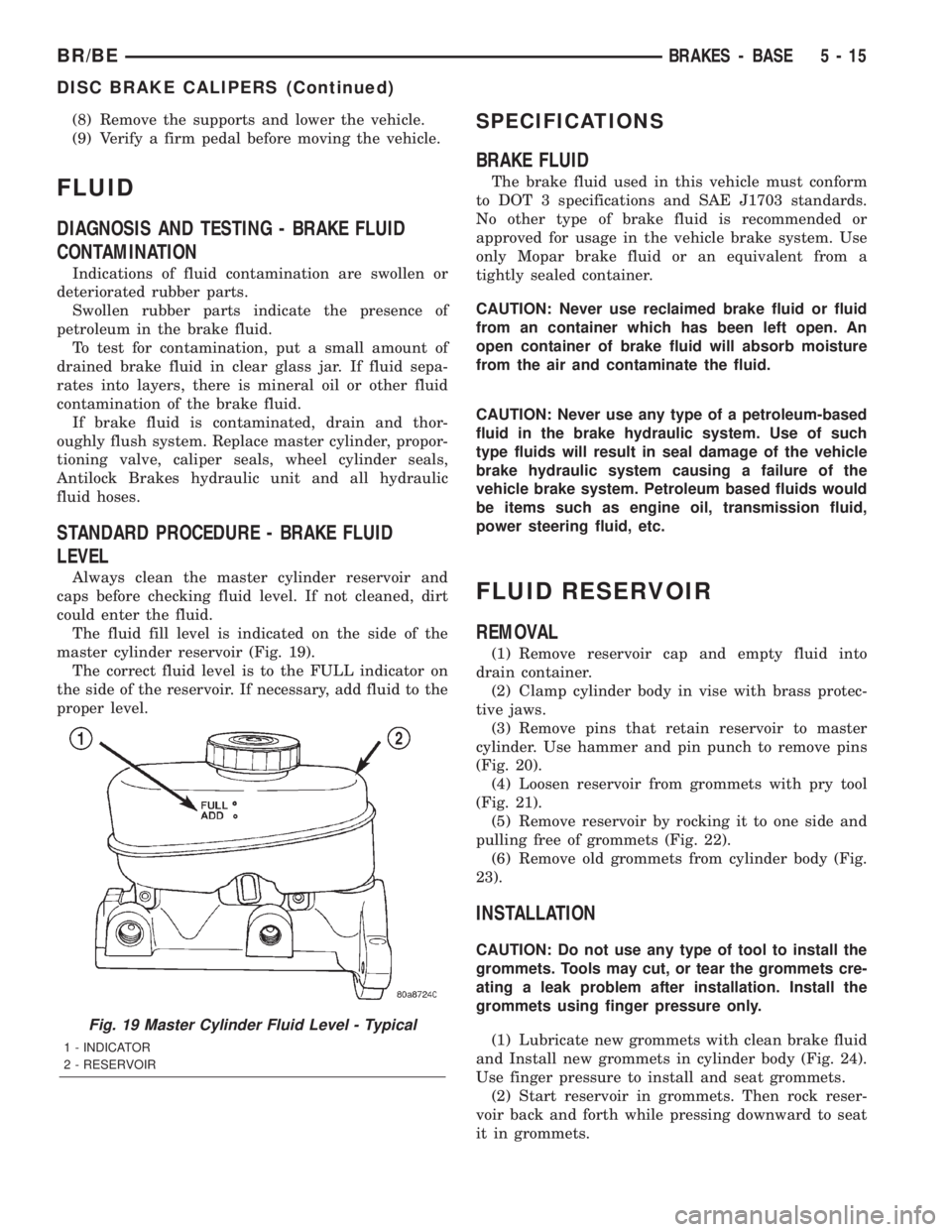
The fluid fill level is indicated on the side of the
master cylinder reservoir (Fig. 19).
The correct fluid level is to the FULL indicator on
the side of the reservoir. If necessary, add fluid to the
proper level.
SPECIFICATIONS
BRAKE FLUID
The brake fluid used in this vehicle must conform
to DOT 3 specifications and SAE J1703 standards.
No other type of brake fluid is recommended or
approved for usage in the vehicle brake system. Use
only Mopar brake fluid or an equivalent from a
tightly sealed container.
CAUTION: Never use reclaimed brake fluid or fluid
from an container which has been left open. An
open container of brake fluid will absorb moisture
from the air and contaminate the fluid.
CAUTION: Never use any type of a petroleum-based
fluid in the brake hydraulic system. Use of such
type fluids will result in seal damage of the vehicle
brake hydraulic system causing a failure of the
vehicle brake system. Petroleum based fluids would
be items such as engine oil, transmission fluid,
power steering fluid, etc.
FLUID RESERVOIR
REMOVAL
(1) Remove reservoir cap and empty fluid into
drain container.
(2) Clamp cylinder body in vise with brass protec-
tive jaws.
(3) Remove pins that retain reservoir to master
cylinder. Use hammer and pin punch to remove pins
(Fig. 20).
(4) Loosen reservoir from grommets with pry tool
(Fig. 21).
(5) Remove reservoir by rocking it to one side and
pulling free of grommets (Fig. 22).
(6) Remove old grommets from cylinder body (Fig.
23).
INSTALLATION
CAUTION: Do not use any type of tool to install the
grommets. Tools may cut, or tear the grommets cre-
ating a leak problem after installation. Install the
grommets using finger pressure only.
(1) Lubricate new grommets with clean brake fluid
and Install new grommets in cylinder body (Fig. 24).
Use finger pressure to install and seat grommets.
(2) Start reservoir in grommets. Then rock reser-
voir back and forth while pressing downward to seat
it in grommets.
Fig. 19 Master Cylinder Fluid Level - Typical
1 - INDICATOR
2 - RESERVOIR
BR/BEBRAKES - BASE 5 - 15
DISC BRAKE CALIPERS (Continued)
Page 215 of 2255
(7) Install caliper, (Refer to 5 - BRAKES/HY-
DRAULIC/MECHANICAL/DISC BRAKE CALIPERS
- INSTALLATION) (Refer to 5 - BRAKES/HYDRAU-
LIC/MECHANICAL/DISC BRAKE CALIPERS -
INSTALLATION).
(8) Install wheel and tire assemblies and lower
vehicle, (Refer to 22 - TIRES/WHEELS/WHEELS -
STANDARD PROCEDURE).
(9) Apply brakes several times to seat caliper pis-
tons and brake shoes and obtain firm pedal.
(10) Top off master cylinder fluid level.
INSTALLATION - FRONT
(1) Bottom pistons in caliper bore with C-clamp.
Place an old brake shoe between a C-clamp and cal-
iper piston.
(2) Clean caliper mounting adapter and anti-rattle
springs.
(3) Lubricate anti-rattle springs with Mopar brake
grease.
(4) Install anti-rattle springs.
NOTE: Anti-rattle springs are not interchangeable.
(5) Install inboard brake shoe in adapter.
(6) Install outboard brake shoe in adapter.
(7) Tilt the bottom of the caliper over rotor and
under adapter. Then push the top of the caliper down
onto the adapter.
(8) Install caliper, (Refer to 5 - BRAKES/HY-
DRAULIC/MECHANICAL/DISC BRAKE CALIPERS
- INSTALLATION).
(9) Install wheel and tire assemblies and lower
vehicle, (Refer to 22 - TIRES/WHEELS/WHEELS -
STANDARD PROCEDURE).
(10) Apply brakes several times to seat caliper pis-
tons and brake shoes and obtain firm pedal.
(11) Top off master cylinder fluid level.
MASTER CYLINDER
DESCRIPTION
A two-piece master cylinder is used on all models.
The cylinder body containing the primary and sec-
ondary pistons is made of aluminum. The removable
fluid reservoir is made of nylon reinforced with glass
fiber. The reservoir stores reserve brake fluid for the
hydraulic brake circuits. The reservoir is the only
serviceable component.
The fluid compartments of the nylon reservoir are
interconnected to permit fluid level equalization.
However, the equalization feature does not affect cir-
cuit separation in the event of a front or rear brake
malfunction. The reservoir compartments will retain
enough fluid to operate the functioning hydraulic cir-
cuit.Care must be exercised when removing/installing
the master cylinder connecting lines. The threads in
the cylinder fluid ports can be damaged if care is not
exercised. Start all brake line fittings by hand to
avoid cross threading.
The cylinder reservoir can be replaced when neces-
sary. However, the aluminum body section of the
master cylinder is not a repairable component.
NOTE: If diagnosis indicates that an internal mal-
function has occurred, the aluminum body section
must be replaced as an assembly.
OPERATION
The master cylinder bore contains a primary and
secondary piston. The primary piston supplies
hydraulic pressure to the front brakes. The secondary
piston supplies hydraulic pressure to the rear brakes.
DIAGNOSIS AND TESTING - MASTER
CYLINDER/POWER BOOSTER
(1) Start engine and check booster vacuum hose
connections. A hissing noise indicates vacuum leak.
Correct any vacuum leak before proceeding.
(2) Stop engine and shift transmission into Neu-
tral.
(3) Pump brake pedal until all vacuum reserve in
booster is depleted.
(4) Press and hold brake pedal under light foot
pressure. The pedal should hold firm, if the pedal
falls away master cylinder is faulty (internal leak-
age).
(5) Start engine and note pedal action. It should
fall away slightly under light foot pressure then hold
firm. If no pedal action is discernible, power booster,
vacuum supply, or vacuum check valve is faulty. Pro-
ceed to the POWER BOOSTER VACUUM TEST.
(6) If the POWER BOOSTER VACUUM TEST
passes, rebuild booster vacuum reserve as follows:
Release brake pedal. Increase engine speed to 1500
rpm, close the throttle and immediately turn off igni-
tion to stop engine.
(7) Wait a minimum of 90 seconds and try brake
action again. Booster should provide two or more vac-
uum assisted pedal applications. If vacuum assist is
not provided, booster is faulty.
POWER BOOSTER VACUUM TEST
(1) Connect vacuum gauge to booster check valve
with short length of hose and T-fitting (Fig. 47).
(2) Start and run engine at curb idle speed for one
minute.
(3) Observe the vacuum supply. If vacuum supply
is not adequate, repair vacuum supply.
5 - 26 BRAKES - BASEBR/BE
BRAKE PADS/SHOES (Continued)
Page 235 of 2255
IMPROPER RELEASE OR CLUTCH ENGAGEMENT
Clutch release or engagement problems are caused
by wear or damage to one or more clutch compo-
nents. A visual inspection of the release components
will usually reveal the problem part.
Release problems can result in hard shifting and
noise. Items to look for are: leaks at the clutch cylin-
ders and interconnecting line; loose slave cylinder
bolts; worn/loose release fork and pivot stud; dam-
aged release bearing; and a worn clutch disc, or pres-
sure plate.
Normal condensation in vehicles that are stored or
out of service for long periods of time can generate
enough corrosion to make the disc stick to the fly-
wheel, or pressure plate. If this condition is experi-
enced, correction only requires that the disc be
loosened manually through the inspection plate open-
ing.
Engagement problems usually result in slip, chat-
ter/shudder, and noisy operation. The primary causes
are clutch disc contamination; clutch disc wear; mis-
alignment, or distortion; flywheel damage; or a com-
bination of the foregoing. A visual inspection is
required to determine the part actually causing the
problem.
CLUTCH MISALIGNMENT
Clutch components must be in proper alignment
with the crankshaft and transmission input shaft.
Misalignment caused by excessive runout or warpage
of any clutch component will cause grab, chatter and
improper clutch release.
CLUTCH COVER AND DISC RUNOUT
Check the clutch disc before installation. Axial
(face) runout of anewdisc should not exceed 0.50
mm (0.020 in.). Measure runout about 6 mm (1/4 in.)
from the outer edge of the disc facing. Obtain
another disc if runout is excessive.
Check condition of the clutch before installation. A
warped cover or diaphragm spring will cause grab
and incomplete release or engagement. Be careful
when handling the cover and disc. Impact can distort
the cover, diaphragm spring, release fingers and the
hub of the clutch disc.
Use an alignment tool when positioning the disc on
the flywheel. The tool prevents accidental misalign-
ment which could result in cover distortion and disc
damage.
A frequent cause of clutch cover distortion (and
consequent misalignment) is improper bolt tighten-
ing.
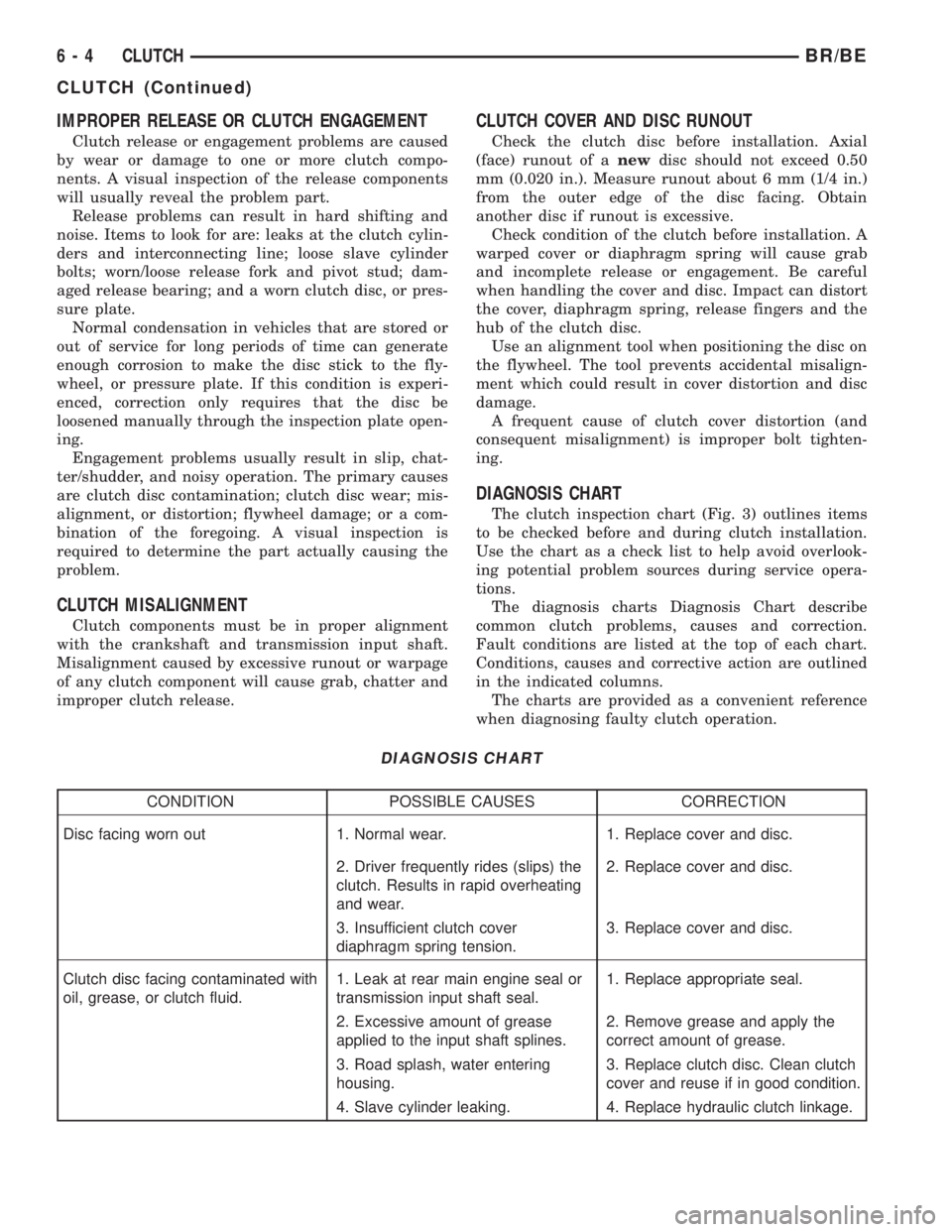
DIAGNOSIS CHART
The clutch inspection chart (Fig. 3) outlines items
to be checked before and during clutch installation.
Use the chart as a check list to help avoid overlook-
ing potential problem sources during service opera-
tions.
The diagnosis charts Diagnosis Chart describe
common clutch problems, causes and correction.
Fault conditions are listed at the top of each chart.
Conditions, causes and corrective action are outlined
in the indicated columns.
The charts are provided as a convenient reference
when diagnosing faulty clutch operation.
DIAGNOSIS CHART
CONDITION POSSIBLE CAUSES CORRECTION
Disc facing worn out 1. Normal wear. 1. Replace cover and disc.
2. Driver frequently rides (slips) the
clutch. Results in rapid overheating
and wear.2. Replace cover and disc.
3. Insufficient clutch cover
diaphragm spring tension.3. Replace cover and disc.
Clutch disc facing contaminated with
oil, grease, or clutch fluid.1. Leak at rear main engine seal or
transmission input shaft seal.1. Replace appropriate seal.
2. Excessive amount of grease
applied to the input shaft splines.2. Remove grease and apply the
correct amount of grease.
3. Road splash, water entering
housing.3. Replace clutch disc. Clean clutch
cover and reuse if in good condition.
4. Slave cylinder leaking. 4. Replace hydraulic clutch linkage.
6 - 4 CLUTCHBR/BE
CLUTCH (Continued)
Page 239 of 2255
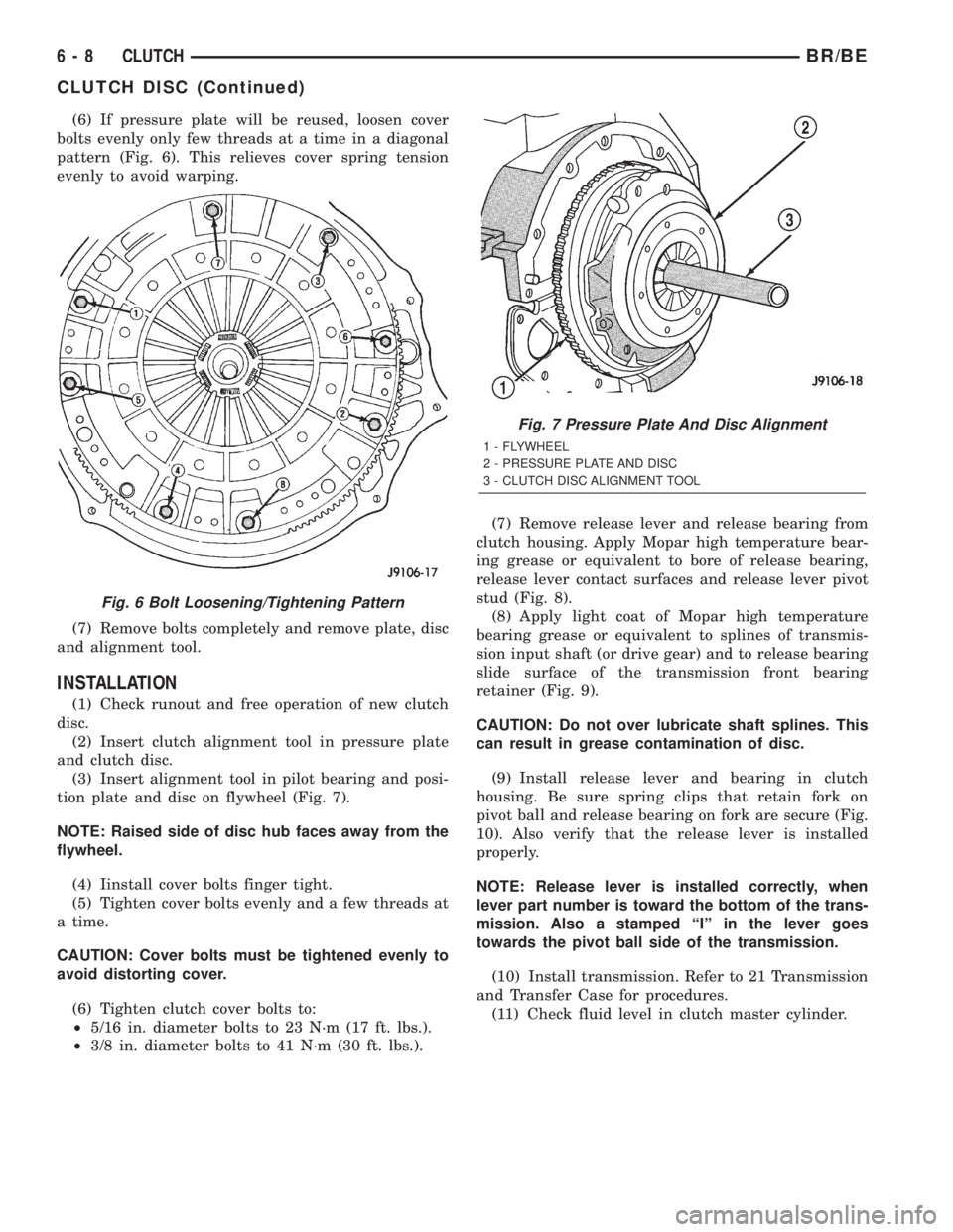
(6) If pressure plate will be reused, loosen cover
bolts evenly only few threads at a time in a diagonal
pattern (Fig. 6). This relieves cover spring tension
evenly to avoid warping.
(7) Remove bolts completely and remove plate, disc
and alignment tool.
INSTALLATION
(1) Check runout and free operation of new clutch
disc.
(2) Insert clutch alignment tool in pressure plate
and clutch disc.
(3) Insert alignment tool in pilot bearing and posi-
tion plate and disc on flywheel (Fig. 7).
NOTE: Raised side of disc hub faces away from the
flywheel.
(4) Iinstall cover bolts finger tight.
(5) Tighten cover bolts evenly and a few threads at
a time.
CAUTION: Cover bolts must be tightened evenly to
avoid distorting cover.
(6) Tighten clutch cover bolts to:
²5/16 in. diameter bolts to 23 N´m (17 ft. lbs.).
²3/8 in. diameter bolts to 41 N´m (30 ft. lbs.).(7) Remove release lever and release bearing from
clutch housing. Apply Mopar high temperature bear-
ing grease or equivalent to bore of release bearing,
release lever contact surfaces and release lever pivot
stud (Fig. 8).
(8) Apply light coat of Mopar high temperature
bearing grease or equivalent to splines of transmis-
sion input shaft (or drive gear) and to release bearing
slide surface of the transmission front bearing
retainer (Fig. 9).
CAUTION: Do not over lubricate shaft splines. This
can result in grease contamination of disc.
(9) Install release lever and bearing in clutch
housing. Be sure spring clips that retain fork on
pivot ball and release bearing on fork are secure (Fig.
10). Also verify that the release lever is installed
properly.
NOTE: Release lever is installed correctly, when
lever part number is toward the bottom of the trans-
mission. Also a stamped ªIº in the lever goes
towards the pivot ball side of the transmission.
(10) Install transmission. Refer to 21 Transmission
and Transfer Case for procedures.
(11) Check fluid level in clutch master cylinder.
Fig. 6 Bolt Loosening/Tightening Pattern
Fig. 7 Pressure Plate And Disc Alignment
1 - FLYWHEEL
2 - PRESSURE PLATE AND DISC
3 - CLUTCH DISC ALIGNMENT TOOL
6 - 8 CLUTCHBR/BE
CLUTCH DISC (Continued)
Page 250 of 2255
COOLING
TABLE OF CONTENTS
page page
COOLING
DESCRIPTION
DESCRIPTION - COOLING SYSTEM FLOW -
5.9L ENGINE..........................1
DESCRIPTIONÐCOOLING SYSTEM FLOW -
5.9L DIESEL..........................2
DESCRIPTIONÐHOSE CLAMPS...........4
OPERATION
OPERATIONÐHOSE CLAMPS............4
OPERATIONÐCOOLING SYSTEM.........4
DIAGNOSIS AND TESTING
DIAGNOSIS AND TESTING - PRELIMINARY
CHECKS.............................4
DIAGNOSIS AND TESTINGÐON-BOARD
DIAGNOSTICS (OBD)...................5
DIAGNOSIS AND TESTING - COOLING
SYSTEM LEAKS.......................5
DIAGNOSIS AND TESTING - COOLING
SYSTEM GAS ENGINE..................7
DIAGNOSIS AND TESTING - COOLING
SYSTEM DIESEL ENGINE...............13
STANDARD PROCEDURE
STANDARD PROCEDURE - DRAINING
COOLING SYSTEM 5.9L/8.0L ENGINES....15STANDARD PROCEDUREÐDRAINING
COOLING SYSTEM 5.9L DIESEL ENGINE . . . 15
STANDARD PROCEDURE - REFILLING
COOLING SYSTEM 5.9L/8.0L ENGINES....16
STANDARD PROCEDUREÐREFILLING
COOLING SYSTEM 5.9L DIESEL ENGINE . . . 16
STANDARD PROCEDURE - ADDING
ADDITIONAL COOLANT.................16
STANDARD PROCEDUREÐCOOLANT
LEVEL CHECK........................16
STANDARD PROCEDURE - COOLING
SYSTEM CLEANING/REVERSE FLUSHING . . 17
STANDARD PROCEDURE - COOLANT
SELECTION - ADDITIVES...............17
SPECIFICATIONS
TORQUE............................18
SPECIAL TOOLS
COOLING...........................18
ACCESSORY DRIVE......................19
ENGINE...............................38
TRANSMISSION.........................78
COOLING
DESCRIPTION
DESCRIPTION - COOLING SYSTEM FLOW -
5.9L ENGINE
The cooling system regulates engine operating tem-
perature. It allows the engine to reach normal oper-
ating temperature as quickly as possible. It also
maintains normal operating temperature and pre-
vents overheating.The cooling system also provides a means of heat-
ing the passenger compartment and cooling the auto-
matic transmission fluid (if equipped). The cooling
system is pressurized and uses a centrifugal water
pump to circulate coolant throughout the system.
An optional factory installed maximum duty cool-
ing package is available on most models. This pack-
age will provide additional cooling capacity for
vehicles used under extreme conditions such as
trailer towing in high ambient temperatures (Fig. 1).
BR/BECOOLING 7 - 1
Page 253 of 2255
DESCRIPTIONÐHOSE CLAMPS
The cooling system utilizes both worm drive and
spring type hose clamps. If a spring type clamp
replacement is necessary, replace with the original
Mopartequipment spring type clamp.
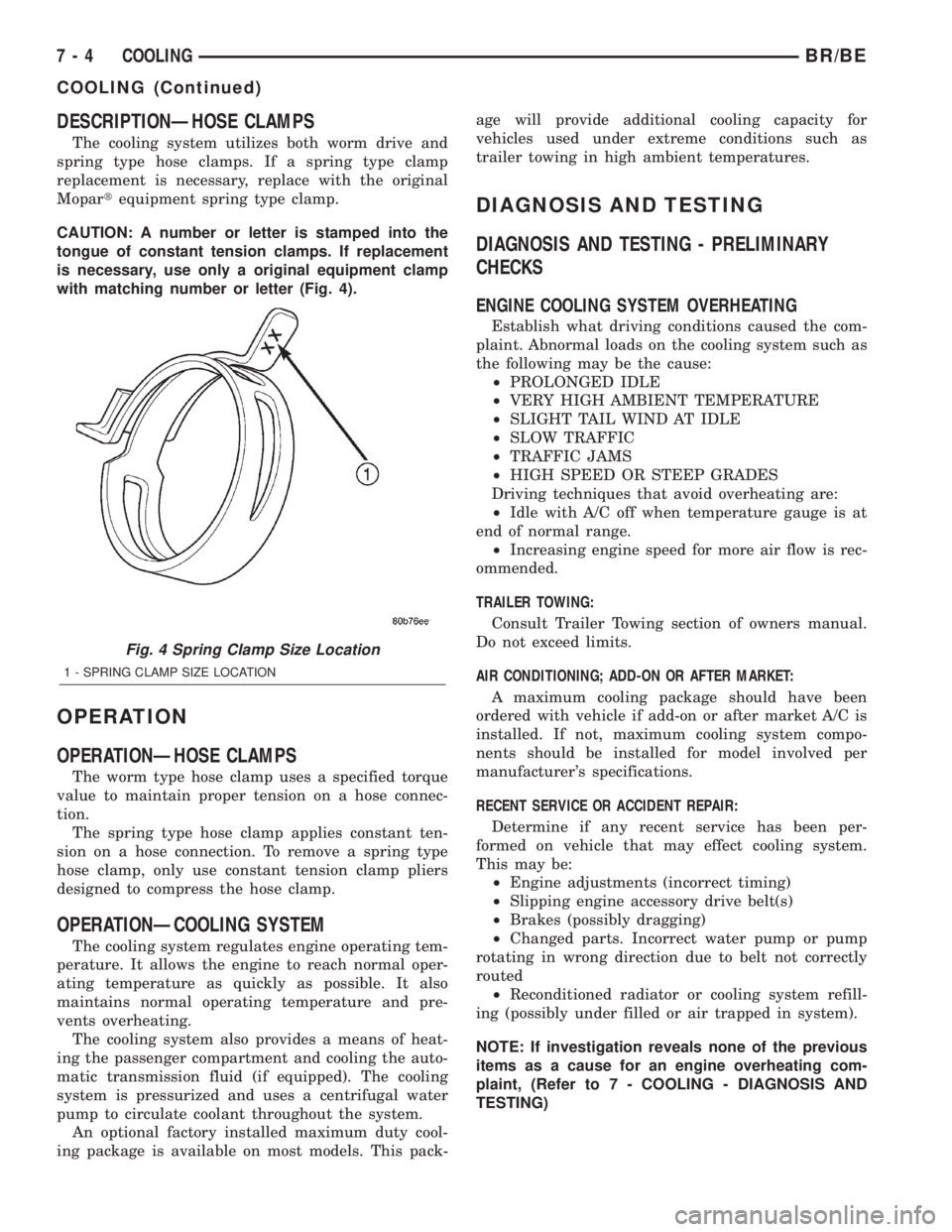
CAUTION: A number or letter is stamped into the
tongue of constant tension clamps. If replacement
is necessary, use only a original equipment clamp
with matching number or letter (Fig. 4).
OPERATION
OPERATIONÐHOSE CLAMPS
The worm type hose clamp uses a specified torque
value to maintain proper tension on a hose connec-
tion.
The spring type hose clamp applies constant ten-
sion on a hose connection. To remove a spring type
hose clamp, only use constant tension clamp pliers
designed to compress the hose clamp.
OPERATIONÐCOOLING SYSTEM
The cooling system regulates engine operating tem-
perature. It allows the engine to reach normal oper-
ating temperature as quickly as possible. It also
maintains normal operating temperature and pre-
vents overheating.
The cooling system also provides a means of heat-
ing the passenger compartment and cooling the auto-
matic transmission fluid (if equipped). The cooling
system is pressurized and uses a centrifugal water
pump to circulate coolant throughout the system.
An optional factory installed maximum duty cool-
ing package is available on most models. This pack-age will provide additional cooling capacity for
vehicles used under extreme conditions such as
trailer towing in high ambient temperatures.
DIAGNOSIS AND TESTING
DIAGNOSIS AND TESTING - PRELIMINARY
CHECKS
ENGINE COOLING SYSTEM OVERHEATING
Establish what driving conditions caused the com-
plaint. Abnormal loads on the cooling system such as
the following may be the cause:
²PROLONGED IDLE
²VERY HIGH AMBIENT TEMPERATURE
²SLIGHT TAIL WIND AT IDLE
²SLOW TRAFFIC
²TRAFFIC JAMS
²HIGH SPEED OR STEEP GRADES
Driving techniques that avoid overheating are:
²Idle with A/C off when temperature gauge is at
end of normal range.
²Increasing engine speed for more air flow is rec-
ommended.
TRAILER TOWING:
Consult Trailer Towing section of owners manual.
Do not exceed limits.
AIR CONDITIONING; ADD-ON OR AFTER MARKET:
A maximum cooling package should have been
ordered with vehicle if add-on or after market A/C is
installed. If not, maximum cooling system compo-
nents should be installed for model involved per
manufacturer's specifications.
RECENT SERVICE OR ACCIDENT REPAIR:
Determine if any recent service has been per-
formed on vehicle that may effect cooling system.
This may be:
²Engine adjustments (incorrect timing)
²Slipping engine accessory drive belt(s)
²Brakes (possibly dragging)
²Changed parts. Incorrect water pump or pump
rotating in wrong direction due to belt not correctly
routed
²Reconditioned radiator or cooling system refill-
ing (possibly under filled or air trapped in system).
NOTE: If investigation reveals none of the previous
items as a cause for an engine overheating com-
plaint, (Refer to 7 - COOLING - DIAGNOSIS AND
TESTING)
Fig. 4 Spring Clamp Size Location
1 - SPRING CLAMP SIZE LOCATION
7 - 4 COOLINGBR/BE
COOLING (Continued)