differential lubrication DODGE RAM 2002 Service Repair Manual
[x] Cancel search | Manufacturer: DODGE, Model Year: 2002, Model line: RAM, Model: DODGE RAM 2002Pages: 2255, PDF Size: 62.07 MB
Page 1 of 2255
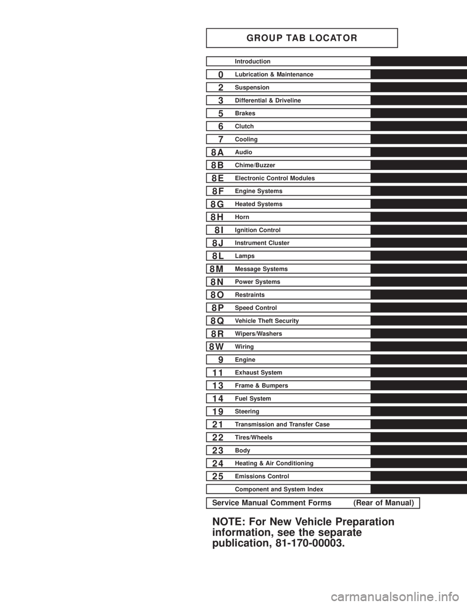
GROUP TAB LOCATOR
Introduction
0Lubrication & Maintenance
2Suspension
3Differential & Driveline
5Brakes
6Clutch
7Cooling
8AAudio
8BChime/Buzzer
8EElectronic Control Modules
8FEngine Systems
8GHeated Systems
8HHorn
8IIgnition Control
8JInstrument Cluster
8LLamps
8MMessage Systems
8NPower Systems
8ORestraints
8PSpeed Control
8QVehicle Theft Security
8RWipers/Washers
8WWiring
9Engine
11Exhaust System
13Frame & Bumpers
14Fuel System
19Steering
21Transmission and Transfer Case
22Tires/Wheels
23Body
24Heating & Air Conditioning
25Emissions Control
Component and System Index
Service Manual Comment Forms (Rear of Manual)
NOTE: For New Vehicle Preparation
information, see the separate
publication, 81-170-00003.
Page 20 of 2255
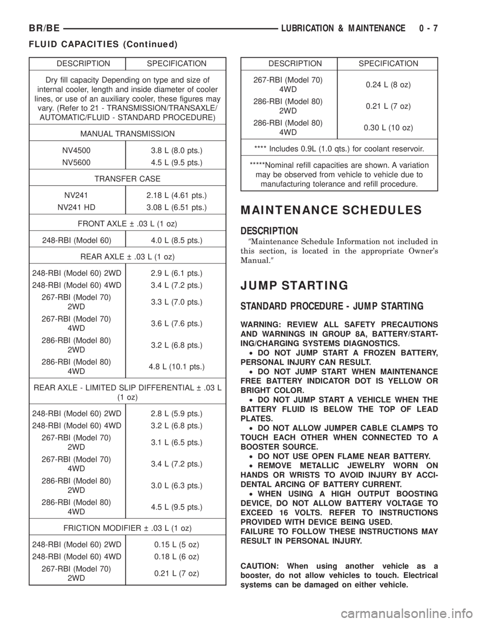
DESCRIPTION SPECIFICATION
Dry fill capacity Depending on type and size of
internal cooler, length and inside diameter of cooler
lines, or use of an auxiliary cooler, these figures may
vary. (Refer to 21 - TRANSMISSION/TRANSAXLE/
AUTOMATIC/FLUID - STANDARD PROCEDURE)
MANUAL TRANSMISSION
NV4500 3.8 L (8.0 pts.)
NV5600 4.5 L (9.5 pts.)
TRANSFER CASE
NV241 2.18 L (4.61 pts.)
NV241 HD 3.08 L (6.51 pts.)
FRONT AXLE .03 L (1 oz)
248-RBI (Model 60) 4.0 L (8.5 pts.)
REAR AXLE .03 L (1 oz)
248-RBI (Model 60) 2WD 2.9 L (6.1 pts.)
248-RBI (Model 60) 4WD 3.4 L (7.2 pts.)
267-RBI (Model 70)
2WD3.3 L (7.0 pts.)
267-RBI (Model 70)
4WD3.6 L (7.6 pts.)
286-RBI (Model 80)
2WD3.2 L (6.8 pts.)
286-RBI (Model 80)
4WD4.8 L (10.1 pts.)
REAR AXLE - LIMITED SLIP DIFFERENTIAL .03 L
(1 oz)
248-RBI (Model 60) 2WD 2.8 L (5.9 pts.)
248-RBI (Model 60) 4WD 3.2 L (6.8 pts.)
267-RBI (Model 70)
2WD3.1 L (6.5 pts.)
267-RBI (Model 70)
4WD3.4 L (7.2 pts.)
286-RBI (Model 80)
2WD3.0 L (6.3 pts.)
286-RBI (Model 80)
4WD4.5 L (9.5 pts.)
FRICTION MODIFIER .03 L (1 oz)
248-RBI (Model 60) 2WD 0.15 L (5 oz)
248-RBI (Model 60) 4WD 0.18 L (6 oz)
267-RBI (Model 70)
2WD0.21 L (7 oz)DESCRIPTION SPECIFICATION
267-RBI (Model 70)
4WD0.24 L (8 oz)
286-RBI (Model 80)
2WD0.21 L (7 oz)
286-RBI (Model 80)
4WD0.30 L (10 oz)
**** Includes 0.9L (1.0 qts.) for coolant reservoir.
*****Nominal refill capacities are shown. A variation
may be observed from vehicle to vehicle due to
manufacturing tolerance and refill procedure.
MAINTENANCE SCHEDULES
DESCRIPTION
9Maintenance Schedule Information not included in
this section, is located in the appropriate Owner's
Manual.9
JUMP STARTING
STANDARD PROCEDURE - JUMP STARTING
WARNING: REVIEW ALL SAFETY PRECAUTIONS
AND WARNINGS IN GROUP 8A, BATTERY/START-
ING/CHARGING SYSTEMS DIAGNOSTICS.
²DO NOT JUMP START A FROZEN BATTERY,
PERSONAL INJURY CAN RESULT.
²DO NOT JUMP START WHEN MAINTENANCE
FREE BATTERY INDICATOR DOT IS YELLOW OR
BRIGHT COLOR.
²DO NOT JUMP START A VEHICLE WHEN THE
BATTERY FLUID IS BELOW THE TOP OF LEAD
PLATES.
²DO NOT ALLOW JUMPER CABLE CLAMPS TO
TOUCH EACH OTHER WHEN CONNECTED TO A
BOOSTER SOURCE.
²DO NOT USE OPEN FLAME NEAR BATTERY.
²REMOVE METALLIC JEWELRY WORN ON
HANDS OR WRISTS TO AVOID INJURY BY ACCI-
DENTAL ARCING OF BATTERY CURRENT.
²WHEN USING A HIGH OUTPUT BOOSTING
DEVICE, DO NOT ALLOW BATTERY VOLTAGE TO
EXCEED 16 VOLTS. REFER TO INSTRUCTIONS
PROVIDED WITH DEVICE BEING USED.
FAILURE TO FOLLOW THESE INSTRUCTIONS MAY
RESULT IN PERSONAL INJURY.
CAUTION: When using another vehicle as a
booster, do not allow vehicles to touch. Electrical
systems can be damaged on either vehicle.
BR/BELUBRICATION & MAINTENANCE 0 - 7
FLUID CAPACITIES (Continued)
Page 72 of 2255
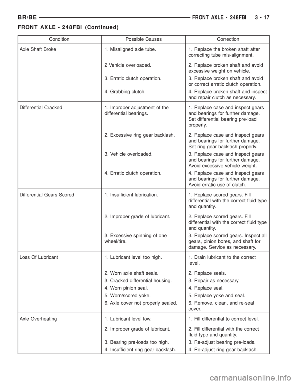
Condition Possible Causes Correction
Axle Shaft Broke 1. Misaligned axle tube. 1. Replace the broken shaft after
correcting tube mis-alignment.
2 Vehicle overloaded. 2. Replace broken shaft and avoid
excessive weight on vehicle.
3. Erratic clutch operation. 3. Replace broken shaft and avoid
or correct erratic clutch operation.
4. Grabbing clutch. 4. Replace broken shaft and inspect
and repair clutch as necessary.
Differential Cracked 1. Improper adjustment of the
differential bearings.1. Replace case and inspect gears
and bearings for further damage.
Set differential bearing pre-load
properly.
2. Excessive ring gear backlash. 2. Replace case and inspect gears
and bearings for further damage.
Set ring gear backlash properly.
3. Vehicle overloaded. 3. Replace case and inspect gears
and bearings for further damage.
Avoid excessive vehicle weight.
4. Erratic clutch operation. 4. Replace case and inspect gears
and bearings for further damage.
Avoid erratic use of clutch.
Differential Gears Scored 1. Insufficient lubrication. 1. Replace scored gears. Fill
differential with the correct fluid type
and quantity.
2. Improper grade of lubricant. 2. Replace scored gears. Fill
differential with the correct fluid type
and quantity.
3. Excessive spinning of one
wheel/tire.3. Replace scored gears. Inspect all
gears, pinion bores, and shaft for
damage. Service as necessary.
Loss Of Lubricant 1. Lubricant level too high. 1. Drain lubricant to the correct
level.
2. Worn axle shaft seals. 2. Replace seals.
3. Cracked differential housing. 3. Repair as necessary.
4. Worn pinion seal. 4. Replace seal.
5. Worn/scored yoke. 5. Replace yoke and seal.
6. Axle cover not properly sealed. 6. Remove, clean, and re-seal
cover.
Axle Overheating 1. Lubricant level low. 1. Fill differential to correct level.
2. Improper grade of lubricant. 2. Fill differential with the correct
fluid type and quantity.
3. Bearing pre-loads too high. 3. Re-adjust bearing pre-loads.
4. Insufficient ring gear backlash. 4. Re-adjust ring gear backlash.
BR/BEFRONT AXLE - 248FBI 3 - 17
FRONT AXLE - 248FBI (Continued)
Page 104 of 2255
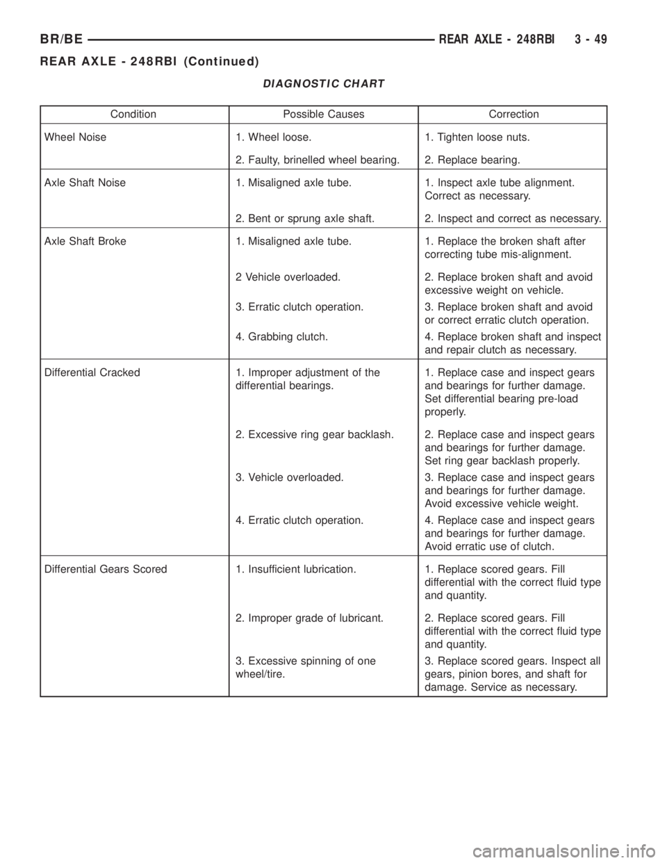
DIAGNOSTIC CHART
Condition Possible Causes Correction
Wheel Noise 1. Wheel loose. 1. Tighten loose nuts.
2. Faulty, brinelled wheel bearing. 2. Replace bearing.
Axle Shaft Noise 1. Misaligned axle tube. 1. Inspect axle tube alignment.
Correct as necessary.
2. Bent or sprung axle shaft. 2. Inspect and correct as necessary.
Axle Shaft Broke 1. Misaligned axle tube. 1. Replace the broken shaft after
correcting tube mis-alignment.
2 Vehicle overloaded. 2. Replace broken shaft and avoid
excessive weight on vehicle.
3. Erratic clutch operation. 3. Replace broken shaft and avoid
or correct erratic clutch operation.
4. Grabbing clutch. 4. Replace broken shaft and inspect
and repair clutch as necessary.
Differential Cracked 1. Improper adjustment of the
differential bearings.1. Replace case and inspect gears
and bearings for further damage.
Set differential bearing pre-load
properly.
2. Excessive ring gear backlash. 2. Replace case and inspect gears
and bearings for further damage.
Set ring gear backlash properly.
3. Vehicle overloaded. 3. Replace case and inspect gears
and bearings for further damage.
Avoid excessive vehicle weight.
4. Erratic clutch operation. 4. Replace case and inspect gears
and bearings for further damage.
Avoid erratic use of clutch.
Differential Gears Scored 1. Insufficient lubrication. 1. Replace scored gears. Fill
differential with the correct fluid type
and quantity.
2. Improper grade of lubricant. 2. Replace scored gears. Fill
differential with the correct fluid type
and quantity.
3. Excessive spinning of one
wheel/tire.3. Replace scored gears. Inspect all
gears, pinion bores, and shaft for
damage. Service as necessary.
BR/BEREAR AXLE - 248RBI 3 - 49
REAR AXLE - 248RBI (Continued)
Page 136 of 2255
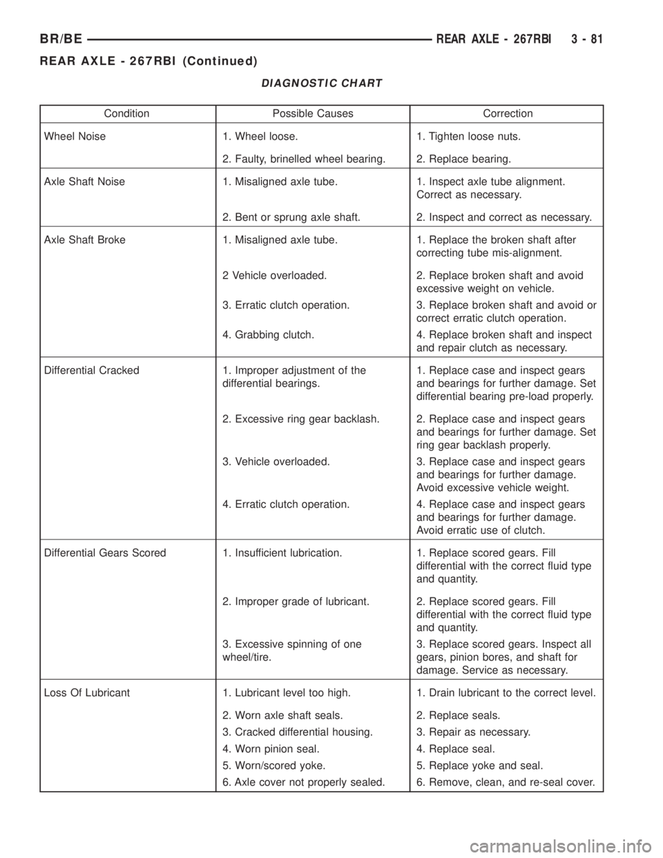
DIAGNOSTIC CHART
Condition Possible Causes Correction
Wheel Noise 1. Wheel loose. 1. Tighten loose nuts.
2. Faulty, brinelled wheel bearing. 2. Replace bearing.
Axle Shaft Noise 1. Misaligned axle tube. 1. Inspect axle tube alignment.
Correct as necessary.
2. Bent or sprung axle shaft. 2. Inspect and correct as necessary.
Axle Shaft Broke 1. Misaligned axle tube. 1. Replace the broken shaft after
correcting tube mis-alignment.
2 Vehicle overloaded. 2. Replace broken shaft and avoid
excessive weight on vehicle.
3. Erratic clutch operation. 3. Replace broken shaft and avoid or
correct erratic clutch operation.
4. Grabbing clutch. 4. Replace broken shaft and inspect
and repair clutch as necessary.
Differential Cracked 1. Improper adjustment of the
differential bearings.1. Replace case and inspect gears
and bearings for further damage. Set
differential bearing pre-load properly.
2. Excessive ring gear backlash. 2. Replace case and inspect gears
and bearings for further damage. Set
ring gear backlash properly.
3. Vehicle overloaded. 3. Replace case and inspect gears
and bearings for further damage.
Avoid excessive vehicle weight.
4. Erratic clutch operation. 4. Replace case and inspect gears
and bearings for further damage.
Avoid erratic use of clutch.
Differential Gears Scored 1. Insufficient lubrication. 1. Replace scored gears. Fill
differential with the correct fluid type
and quantity.
2. Improper grade of lubricant. 2. Replace scored gears. Fill
differential with the correct fluid type
and quantity.
3. Excessive spinning of one
wheel/tire.3. Replace scored gears. Inspect all
gears, pinion bores, and shaft for
damage. Service as necessary.
Loss Of Lubricant 1. Lubricant level too high. 1. Drain lubricant to the correct level.
2. Worn axle shaft seals. 2. Replace seals.
3. Cracked differential housing. 3. Repair as necessary.
4. Worn pinion seal. 4. Replace seal.
5. Worn/scored yoke. 5. Replace yoke and seal.
6. Axle cover not properly sealed. 6. Remove, clean, and re-seal cover.
BR/BEREAR AXLE - 267RBI 3 - 81
REAR AXLE - 267RBI (Continued)
Page 156 of 2255
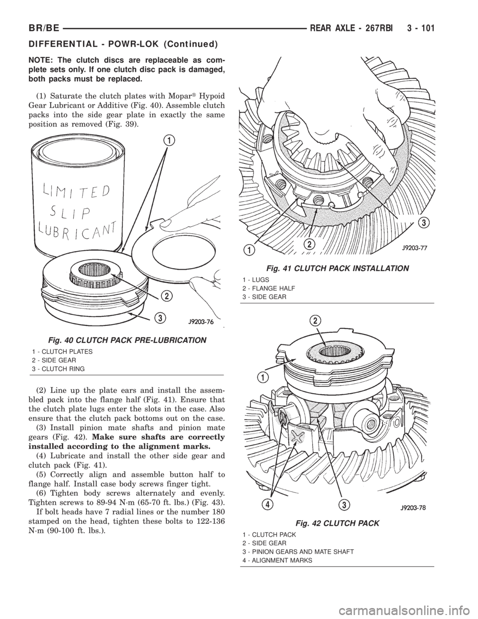
NOTE: The clutch discs are replaceable as com-
plete sets only. If one clutch disc pack is damaged,
both packs must be replaced.
(1) Saturate the clutch plates with MopartHypoid
Gear Lubricant or Additive (Fig. 40). Assemble clutch
packs into the side gear plate in exactly the same
position as removed (Fig. 39).
(2) Line up the plate ears and install the assem-
bled pack into the flange half (Fig. 41). Ensure that
the clutch plate lugs enter the slots in the case. Also
ensure that the clutch pack bottoms out on the case.
(3) Install pinion mate shafts and pinion mate
gears (Fig. 42).Make sure shafts are correctly
installed according to the alignment marks.
(4) Lubricate and install the other side gear and
clutch pack (Fig. 41).
(5) Correctly align and assemble button half to
flange half. Install case body screws finger tight.
(6) Tighten body screws alternately and evenly.
Tighten screws to 89-94 N´m (65-70 ft. lbs.) (Fig. 43).
If bolt heads have 7 radial lines or the number 180
stamped on the head, tighten these bolts to 122-136
N´m (90-100 ft. lbs.).
Fig. 40 CLUTCH PACK PRE-LUBRICATION
1 - CLUTCH PLATES
2 - SIDE GEAR
3 - CLUTCH RING
Fig. 41 CLUTCH PACK INSTALLATION
1 - LUGS
2 - FLANGE HALF
3 - SIDE GEAR
Fig. 42 CLUTCH PACK
1 - CLUTCH PACK
2 - SIDE GEAR
3 - PINION GEARS AND MATE SHAFT
4 - ALIGNMENT MARKS
BR/BEREAR AXLE - 267RBI 3 - 101
DIFFERENTIAL - POWR-LOK (Continued)
Page 165 of 2255
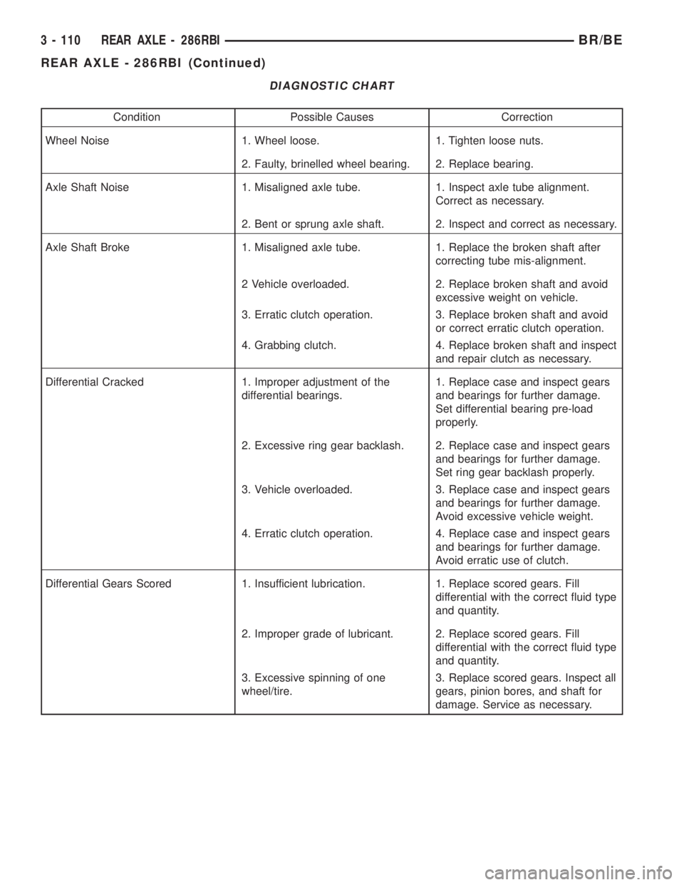
DIAGNOSTIC CHART
Condition Possible Causes Correction
Wheel Noise 1. Wheel loose. 1. Tighten loose nuts.
2. Faulty, brinelled wheel bearing. 2. Replace bearing.
Axle Shaft Noise 1. Misaligned axle tube. 1. Inspect axle tube alignment.
Correct as necessary.
2. Bent or sprung axle shaft. 2. Inspect and correct as necessary.
Axle Shaft Broke 1. Misaligned axle tube. 1. Replace the broken shaft after
correcting tube mis-alignment.
2 Vehicle overloaded. 2. Replace broken shaft and avoid
excessive weight on vehicle.
3. Erratic clutch operation. 3. Replace broken shaft and avoid
or correct erratic clutch operation.
4. Grabbing clutch. 4. Replace broken shaft and inspect
and repair clutch as necessary.
Differential Cracked 1. Improper adjustment of the
differential bearings.1. Replace case and inspect gears
and bearings for further damage.
Set differential bearing pre-load
properly.
2. Excessive ring gear backlash. 2. Replace case and inspect gears
and bearings for further damage.
Set ring gear backlash properly.
3. Vehicle overloaded. 3. Replace case and inspect gears
and bearings for further damage.
Avoid excessive vehicle weight.
4. Erratic clutch operation. 4. Replace case and inspect gears
and bearings for further damage.
Avoid erratic use of clutch.
Differential Gears Scored 1. Insufficient lubrication. 1. Replace scored gears. Fill
differential with the correct fluid type
and quantity.
2. Improper grade of lubricant. 2. Replace scored gears. Fill
differential with the correct fluid type
and quantity.
3. Excessive spinning of one
wheel/tire.3. Replace scored gears. Inspect all
gears, pinion bores, and shaft for
damage. Service as necessary.
3 - 110 REAR AXLE - 286RBIBR/BE
REAR AXLE - 286RBI (Continued)
Page 1687 of 2255
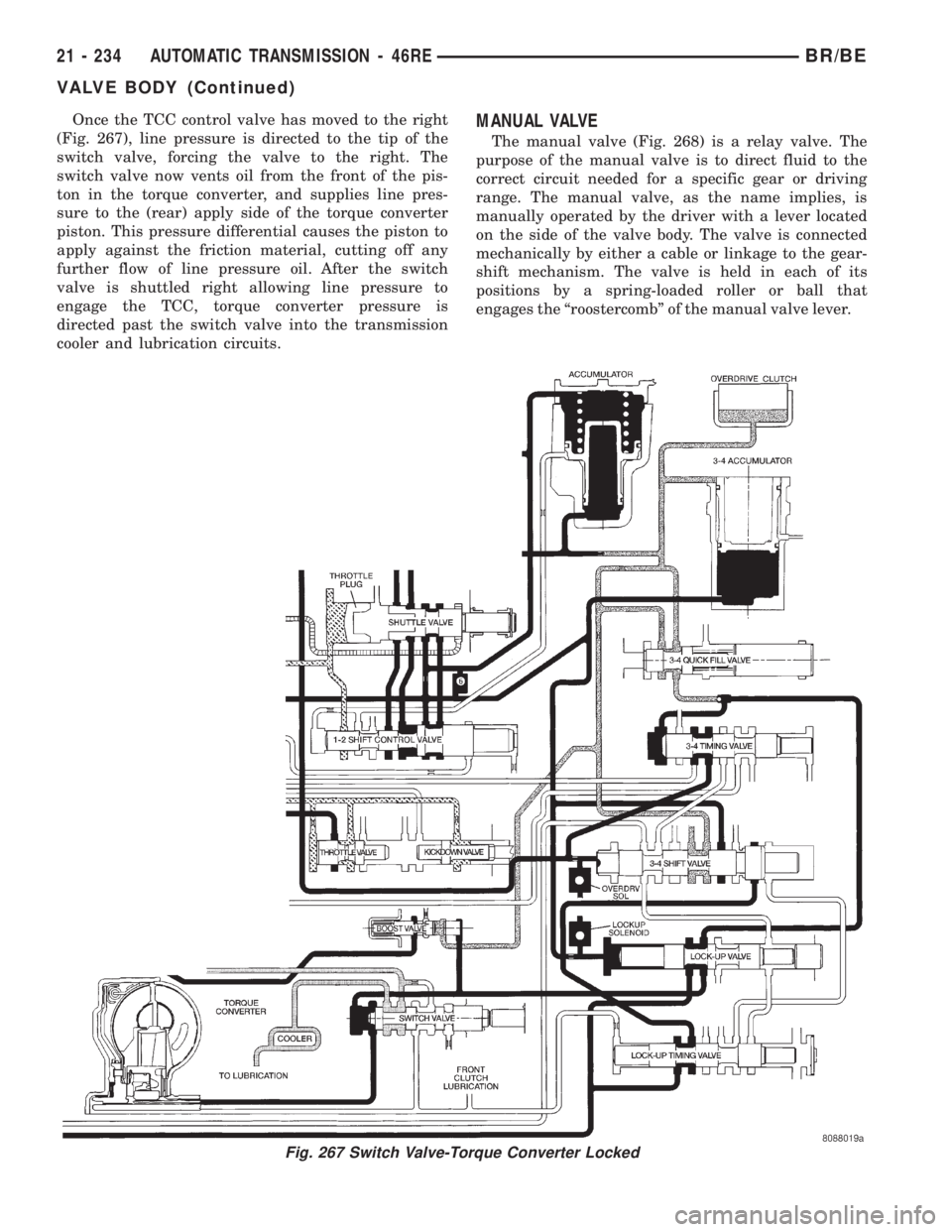
Once the TCC control valve has moved to the right
(Fig. 267), line pressure is directed to the tip of the
switch valve, forcing the valve to the right. The
switch valve now vents oil from the front of the pis-
ton in the torque converter, and supplies line pres-
sure to the (rear) apply side of the torque converter
piston. This pressure differential causes the piston to
apply against the friction material, cutting off any
further flow of line pressure oil. After the switch
valve is shuttled right allowing line pressure to
engage the TCC, torque converter pressure is
directed past the switch valve into the transmission
cooler and lubrication circuits.MANUAL VALVE
The manual valve (Fig. 268) is a relay valve. The
purpose of the manual valve is to direct fluid to the
correct circuit needed for a specific gear or driving
range. The manual valve, as the name implies, is
manually operated by the driver with a lever located
on the side of the valve body. The valve is connected
mechanically by either a cable or linkage to the gear-
shift mechanism. The valve is held in each of its
positions by a spring-loaded roller or ball that
engages the ªroostercombº of the manual valve lever.
Fig. 267 Switch Valve-Torque Converter Locked
21 - 234 AUTOMATIC TRANSMISSION - 46REBR/BE
VALVE BODY (Continued)
Page 1858 of 2255
The higher engine speed and line pressure would
open the vent too far and reduce line pressure too
much. Throttle pressure, which increases with engine
speed (throttle opening), is used to oppose the move-
ment of the pressure valve to help control the meter-
ing passage at the vent. The throttle pressure is
combined with spring pressure to reduce the force of
the throttle pressure plug on the pressure valve. The
larger spring at the right closes the regulator valve
passage and maintains or increases line pressure.
The increased line pressure works against the reac-
tion area of the line pressure plug and the reaction
area left of land #3 simultaneously moves the regu-
lator valve train to the right and controls the meter-
ing passage.
The kickdown valve, along with the throttle valve,
serve to delay upshifts until the correct vehicle speed
has been reached. It also controls downshifts upon
driver demand, or increased engine load. If these
valves were not in place, the shift points would be at
the same speed for all throttle positions. The kick-
down valve is actuated by a cam connected to the
throttle. This is accomplished through either a link-
age or a cable. The cam forces the kickdown valve
toward the throttle valve compressing the spring
between them and moving the throttle valve. As the
throttle valve land starts to uncover its port, line
pressure is ªmeteredº out into the circuits and viewed
as throttle pressure. This increased throttle pressure
is metered out into the circuits it is applied to: the
1-2 and 2-3 shift valves. When the throttle pressure
is high enough, a 3-2 downshift will occur. If the
vehicle speed is low enough, a 2-1 downshift will
occur.
SWITCH VALVE
When the transmission is in Drive Second before
the TCC application occurs (Fig. 258), the pressure
regulator valve is supplying torque converter pres-
sure to the switch valve. The switch valve directs
this pressure through the transmission input shaft,
into the converter, through the converter, back out
between the input shaft and the reaction shaft, and
back up to the switch valve. From the switch valve,
the fluid pressure is directed to the transmission
cooler, and lubrication pressure returns from the
cooler to lubricate different portions of the transmis-
sion.Once the TCC control valve has moved to the right
(Fig. 259), line pressure is directed to the tip of the
switch valve, forcing the valve to the right. The
switch valve now vents oil from the front of the pis-
ton in the torque converter, and supplies line pres-
sure to the (rear) apply side of the torque converter
piston. This pressure differential causes the piston to
apply against the friction material, cutting off any
further flow of line pressure oil. After the switch
valve is shuttled right allowing line pressure to
engage the TCC, torque converter pressure is
directed past the switch valve into the transmission
cooler and lubrication circuits.
MANUAL VALVE
The manual valve (Fig. 260) is a relay valve. The
purpose of the manual valve is to direct fluid to the
correct circuit needed for a specific gear or driving
range. The manual valve, as the name implies, is
manually operated by the driver with a lever located
on the side of the valve body. The valve is connected
mechanically by either a cable or linkage to the gear-
shift mechanism. The valve is held in each of its
positions by a spring-loaded roller or ball that
engages the ªroostercombº of the manual valve lever.
CONVERTER CLUTCH LOCK-UP VALVE
The torque converter clutch (TCC) lock-up valve
controls the back (ON) side of the torque converter
clutch. When the PCM energizes the TCC solenoid to
engage the converter clutch piston, pressure is
applied to the TCC lock-up valve which moves to the
right and applies pressure to the torque converter
clutch.
CONVERTER CLUTCH LOCK-UP TIMING VALVE
The torque converter clutch (TCC) lock-up timing
valve is there to block any 4-3 downshift until the
TCC is completely unlocked and the clutch is disen-
gaged.
BR/BEAUTOMATIC TRANSMISSION - 47RE 21 - 405
VALVE BODY (Continued)
Page 1964 of 2255
DIAGNOSIS AND TESTING - TIRE NOISE OR
VIBRATION
Radial-ply tires are sensitive to force impulses
caused by improper mounting, vibration, wheel
defects, or possibly tire imbalance.
To find out if tires are causing the noise or vibra-
tion, drive the vehicle over a smooth road at varying
speeds. Note the noise level during acceleration and
deceleration. The engine, differential and exhaust
noises will change as speed varies, while the tire
noise will usually remain constant.
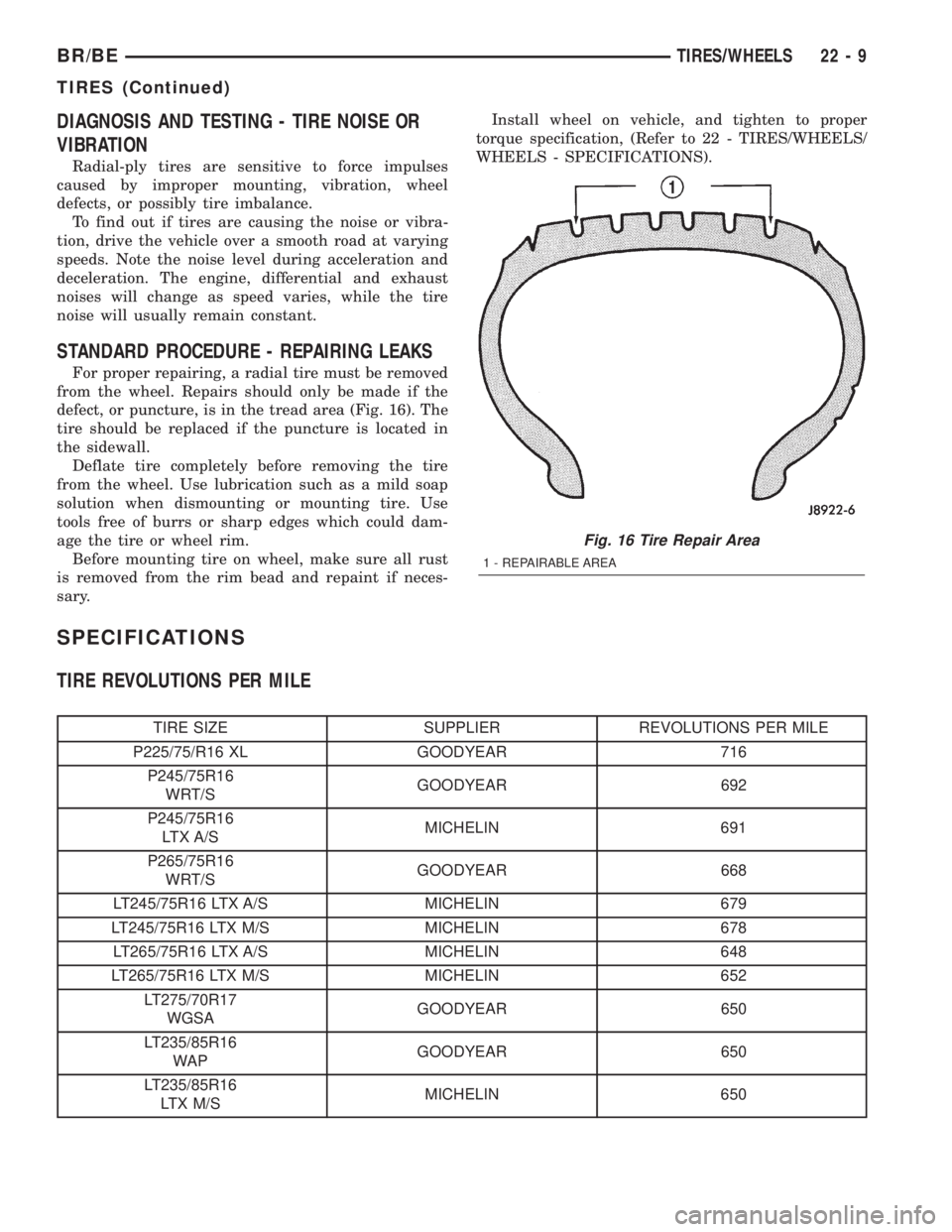
STANDARD PROCEDURE - REPAIRING LEAKS
For proper repairing, a radial tire must be removed
from the wheel. Repairs should only be made if the
defect, or puncture, is in the tread area (Fig. 16). The
tire should be replaced if the puncture is located in
the sidewall.
Deflate tire completely before removing the tire
from the wheel. Use lubrication such as a mild soap
solution when dismounting or mounting tire. Use
tools free of burrs or sharp edges which could dam-
age the tire or wheel rim.
Before mounting tire on wheel, make sure all rust
is removed from the rim bead and repaint if neces-
sary.Install wheel on vehicle, and tighten to proper
torque specification, (Refer to 22 - TIRES/WHEELS/
WHEELS - SPECIFICATIONS).
SPECIFICATIONS
TIRE REVOLUTIONS PER MILE
TIRE SIZE SUPPLIER REVOLUTIONS PER MILE
P225/75/R16 XL GOODYEAR 716
P245/75R16
WRT/SGOODYEAR 692
P245/75R16
LTX A/SMICHELIN 691
P265/75R16
WRT/SGOODYEAR 668
LT245/75R16 LTX A/S MICHELIN 679
LT245/75R16 LTX M/S MICHELIN 678
LT265/75R16 LTX A/S MICHELIN 648
LT265/75R16 LTX M/S MICHELIN 652
LT275/70R17
WGSAGOODYEAR 650
LT235/85R16
WAPGOODYEAR 650
LT235/85R16
LTX M/SMICHELIN 650
Fig. 16 Tire Repair Area
1 - REPAIRABLE AREA
BR/BETIRES/WHEELS 22 - 9
TIRES (Continued)