tire size DODGE RAM 2002 Service Repair Manual
[x] Cancel search | Manufacturer: DODGE, Model Year: 2002, Model line: RAM, Model: DODGE RAM 2002Pages: 2255, PDF Size: 62.07 MB
Page 2 of 2255
INTRODUCTION
TABLE OF CONTENTS
page page
VEHICLE SAFETY CERTIFICATION LABEL
DESCRIPTION..........................1
VEHICLE IDENTIFICATION NUMBER
DESCRIPTION..........................1
VEHICLE EMISSION CONTROL INFORMATION
(VECI)
DESCRIPTION..........................3
EQUIPMENT IDENTIFICATION PLATE
DESCRIPTION..........................3
BODY CODE PLATE
DESCRIPTION..........................4
INTERNATIONAL VEHICLE CONTROL &
DISPLAY SYMBOLS
DESCRIPTION - INTERNATIONAL SYMBOLS . . . 5FASTENER IDENTIFICATION
DESCRIPTION..........................6
FASTENER USAGE
DESCRIPTION..........................9
THREADED HOLE REPAIR
DESCRIPTION..........................9
METRIC SYSTEM
DESCRIPTION..........................9
TORQUE REFERENCES
DESCRIPTION.........................11
VEHICLE SAFETY
CERTIFICATION LABEL
DESCRIPTION
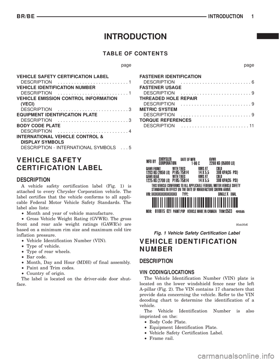
A vehicle safety certification label (Fig. 1) is
attached to every Chrysler Corporation vehicle. The
label certifies that the vehicle conforms to all appli-
cable Federal Motor Vehicle Safety Standards. The
label also lists:
²Month and year of vehicle manufacture.
²Gross Vehicle Weight Rating (GVWR). The gross
front and rear axle weight ratings (GAWR's) are
based on a minimum rim size and maximum cold tire
inflation pressure.
²Vehicle Identification Number (VIN).
²Type of vehicle.
²Type of rear wheels.
²Bar code.
²Month, Day and Hour (MDH) of final assembly.
²Paint and Trim codes.
²Country of origin.
The label is located on the driver-side door shut-
face.
VEHICLE IDENTIFICATION
NUMBER
DESCRIPTION
VIN CODING/LOCATIONS
The Vehicle Identification Number (VIN) plate is
located on the lower windshield fence near the left
A-pillar (Fig. 2). The VIN contains 17 characters that
provide data concerning the vehicle. Refer to the VIN
decoding chart to determine the identification of a
vehicle.
The Vehicle Identification Number is also
imprinted on the:
²Body Code Plate.
²Equipment Identification Plate.
²Vehicle Safety Certification Label.
²Frame rail.
Fig. 1 Vehicle Safety Certification Label
BR/BEINTRODUCTION 1
Page 27 of 2255
OPERATION
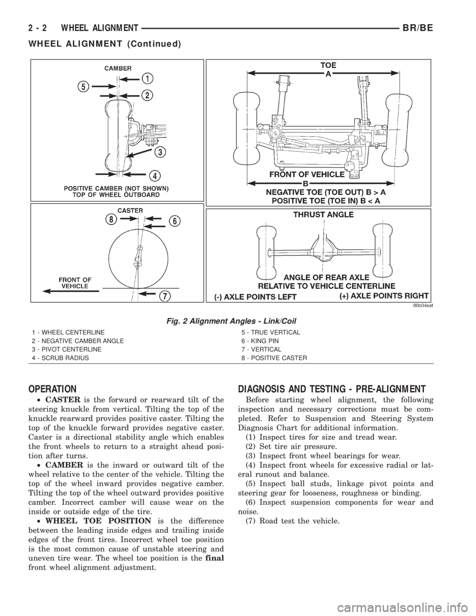
²CASTERis the forward or rearward tilt of the
steering knuckle from vertical. Tilting the top of the
knuckle rearward provides positive caster. Tilting the
top of the knuckle forward provides negative caster.
Caster is a directional stability angle which enables
the front wheels to return to a straight ahead posi-
tion after turns.
²CAMBERis the inward or outward tilt of the
wheel relative to the center of the vehicle. Tilting the
top of the wheel inward provides negative camber.
Tilting the top of the wheel outward provides positive
camber. Incorrect camber will cause wear on the
inside or outside edge of the tire.
²WHEEL TOE POSITIONis the difference
between the leading inside edges and trailing inside
edges of the front tires. Incorrect wheel toe position
is the most common cause of unstable steering and
uneven tire wear. The wheel toe position is thefinal
front wheel alignment adjustment.
DIAGNOSIS AND TESTING - PRE-ALIGNMENT
Before starting wheel alignment, the following
inspection and necessary corrections must be com-
pleted. Refer to Suspension and Steering System
Diagnosis Chart for additional information.
(1) Inspect tires for size and tread wear.
(2) Set tire air pressure.
(3) Inspect front wheel bearings for wear.
(4) Inspect front wheels for excessive radial or lat-
eral runout and balance.
(5) Inspect ball studs, linkage pivot points and
steering gear for looseness, roughness or binding.
(6) Inspect suspension components for wear and
noise.
(7) Road test the vehicle.
Fig. 2 Alignment Angles - Link/Coil
1 - WHEEL CENTERLINE
2 - NEGATIVE CAMBER ANGLE
3 - PIVOT CENTERLINE
4 - SCRUB RADIUS5 - TRUE VERTICAL
6 - KING PIN
7 - VERTICAL
8 - POSITIVE CASTER
2 - 2 WHEEL ALIGNMENTBR/BE
WHEEL ALIGNMENT (Continued)
Page 1066 of 2255
tor between many of the engine compartment, instru-
ment panel, and body wire harnesses. The JB houses
up to nineteen blade-type fuses (two standard-type
and seventeen mini-type), up to two blade-type auto-
matic resetting circuit breakers, the electronic combi-
nation turn signal and hazard warning flasher, and
one International Standards Organization (ISO)
micro-relay.
The molded plastic JB housing has integral mount-
ing brackets that are secured with two screws to the
left instrument panel end bracket. The left end of the
instrument panel cover has a snap-fit fuse access
panel that can be removed for service of the JB. A
fuse puller and spare fuse holders are located on the
back of the fuse access cover, as well as an adhesive-
backed fuse layout map to ensure proper fuse identi-
fication.
The JB unit cannot be repaired and is only ser-
viced as an assembly. If any internal circuit or the JB
housing is faulty or damaged, the entire JB unit
must be replaced.
OPERATION
All of the circuits entering and leaving the JB do
so through up to nine wire harness connectors, which
are connected to the JB through integral connector
receptacles molded into the JB housing. Internal con-
nection of all of the JB circuits is accomplished by an
intricate combination of hard wiring and bus bars.
Refer toWiring Diagramsfor the location of com-
plete JB circuit diagrams.
DIAGNOSIS AND TESTING - JUNCTION BLOCK
The junction block does not incorporate any self
diagnostic capability. Most of the electrical circuits
incorporated into the vehicle must pass through the
junction block at one point or another. The most effi-
cient means of diagnosing a suspected junction block
problem involves a simple continuity tester or ohm
meter. Using the Wiring Diagrams as a guide trace
the problem circuit to the proper junction block cav-
ity and test all circuits in the effected circuit for
proper continuity. A open or high resistance circuit is
a sign of a problem. Some other possible junction
block problems to look for are:
²Loose fuse receptacle terminals.
²Loose relay / circuit breaker receptacle termi-
nals.
²Bent or distorted electrical circuit pins.
²Incorrect size fuse installed in junction block
fuse cavity.
²Dark areas identifying a source of excess heat.
²Defective fuse, relay or circuit breaker installed
in junction block cavity.
REMOVAL
(1) Disconnect and isolate the battery negative
cable.
(2) Remove the fuse access bezel from the instru-
ment panel.
(3) Remove the steering column cover (Refer to 23
- BODY/INSTRUMENT PANEL/STEERING COL-
UMN OPENING COVER - REMOVAL).
(4) Remove the hood release handle retaining
screws and position the handle assembly out of the
way.
(5) Remove the lower knee blocker from the instru-
ment panel.
(6) Pull drivers side carpet down, out of the way.
(7) Remove the parking brake switch connector,
release linkage and retaining fasteners and position
the assembly out the drivers door opening.
(8) Remove the electrical ground connections,
located behind park brake mounting location.
(9) Remove the two junction block retaining
screws. To access the upper retaining screw a 15 inch
long #2 Phillips screwdriver will be required. Access
the upper screw through hole in dash support brace.
(10) Reach through the outboard side of the instru-
ment panel steering column opening to access and
disconnect all of the wire harness connectors from
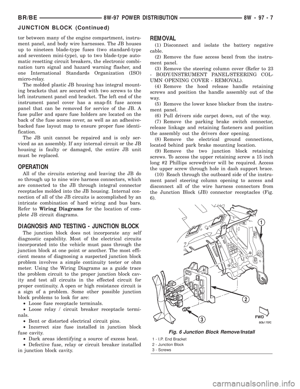
the Junction Block (JB) connector receptacles (Fig.
6).
Fig. 6 Junction Block Remove/Install
1 - I.P. End Bracket
2 - Junction Block
3 - Screws
BR/BE8W-97 POWER DISTRIBUTION 8W - 97 - 7
JUNCTION BLOCK (Continued)
Page 1411 of 2255
DIAGNOSIS AND TESTING
DIAGNOSIS AND TESTING - POWER STEERING SYSTEM
STEERING NOISE
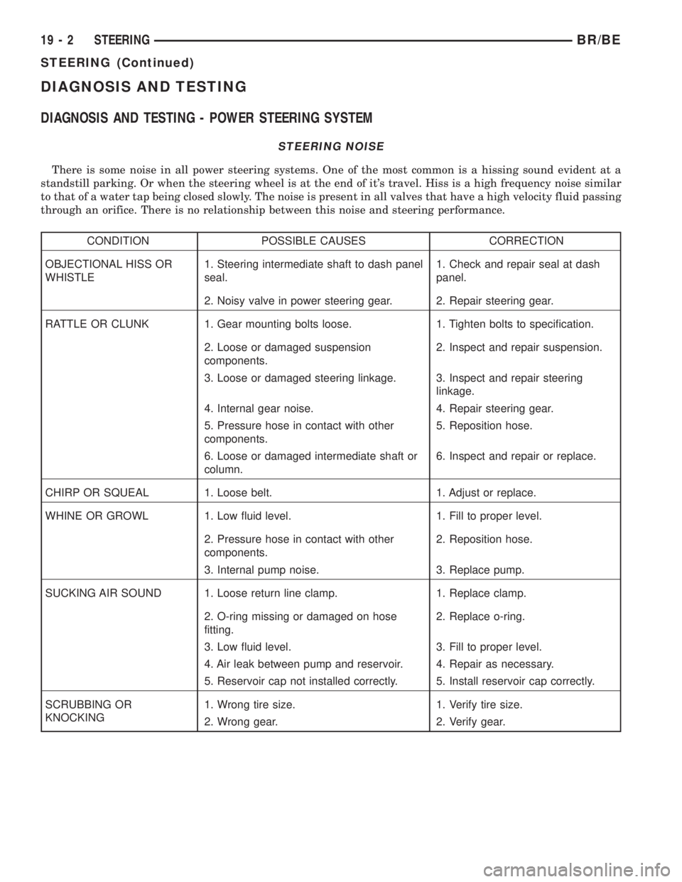
There is some noise in all power steering systems. One of the most common is a hissing sound evident at a
standstill parking. Or when the steering wheel is at the end of it's travel. Hiss is a high frequency noise similar
to that of a water tap being closed slowly. The noise is present in all valves that have a high velocity fluid passing
through an orifice. There is no relationship between this noise and steering performance.
CONDITION POSSIBLE CAUSES CORRECTION
OBJECTIONAL HISS OR
WHISTLE1. Steering intermediate shaft to dash panel
seal.1. Check and repair seal at dash
panel.
2. Noisy valve in power steering gear. 2. Repair steering gear.
RATTLE OR CLUNK 1. Gear mounting bolts loose. 1. Tighten bolts to specification.
2. Loose or damaged suspension
components.2. Inspect and repair suspension.
3. Loose or damaged steering linkage. 3. Inspect and repair steering
linkage.
4. Internal gear noise. 4. Repair steering gear.
5. Pressure hose in contact with other
components.5. Reposition hose.
6. Loose or damaged intermediate shaft or
column.6. Inspect and repair or replace.
CHIRP OR SQUEAL 1. Loose belt. 1. Adjust or replace.
WHINE OR GROWL 1. Low fluid level. 1. Fill to proper level.
2. Pressure hose in contact with other
components.2. Reposition hose.
3. Internal pump noise. 3. Replace pump.
SUCKING AIR SOUND 1. Loose return line clamp. 1. Replace clamp.
2. O-ring missing or damaged on hose
fitting.2. Replace o-ring.
3. Low fluid level. 3. Fill to proper level.
4. Air leak between pump and reservoir. 4. Repair as necessary.
5. Reservoir cap not installed correctly. 5. Install reservoir cap correctly.
SCRUBBING OR
KNOCKING1. Wrong tire size. 1. Verify tire size.
2. Wrong gear. 2. Verify gear.
19 - 2 STEERINGBR/BE
STEERING (Continued)
Page 1567 of 2255
STANDARD PROCEDURE - ALUMINUM
THREAD REPAIR
Damaged or worn threads in the aluminum trans-
mission case and valve body can be repaired by the
use of Heli-CoilsŸ, or equivalent. This repair con-
sists of drilling out the worn-out damaged threads.
Then tap the hole with a special Heli-CoilŸ tap, or
equivalent, and installing a Heli-CoilŸ insert, or
equivalent, into the hole. This brings the hole back to
its original thread size.
Heli-CoilŸ, or equivalent, tools and inserts are
readily available from most automotive parts suppli-
ers.
REMOVAL
The overdrive unit can be removed and serviced
separately. It is not necessary to remove the entire
transmission assembly to perform overdrive unit
repairs.
(1) Disconnect battery negative cable.
(2) Disconnect and lower or remove necessary
exhaust components.
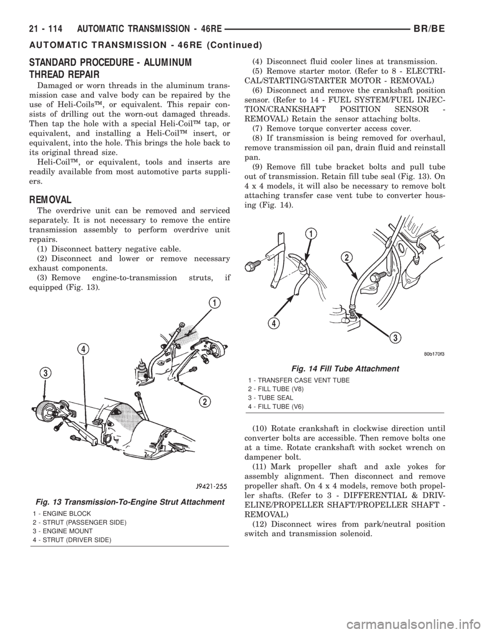
(3) Remove engine-to-transmission struts, if
equipped (Fig. 13).(4) Disconnect fluid cooler lines at transmission.
(5) Remove starter motor. (Refer to 8 - ELECTRI-
CAL/STARTING/STARTER MOTOR - REMOVAL)
(6) Disconnect and remove the crankshaft position
sensor. (Refer to 14 - FUEL SYSTEM/FUEL INJEC-
TION/CRANKSHAFT POSITION SENSOR -
REMOVAL) Retain the sensor attaching bolts.
(7) Remove torque converter access cover.
(8) If transmission is being removed for overhaul,
remove transmission oil pan, drain fluid and reinstall
pan.
(9) Remove fill tube bracket bolts and pull tube
out of transmission. Retain fill tube seal (Fig. 13). On
4 x 4 models, it will also be necessary to remove bolt
attaching transfer case vent tube to converter hous-
ing (Fig. 14).
(10) Rotate crankshaft in clockwise direction until
converter bolts are accessible. Then remove bolts one
at a time. Rotate crankshaft with socket wrench on
dampener bolt.
(11) Mark propeller shaft and axle yokes for
assembly alignment. Then disconnect and remove
propeller shaft. On4x4models, remove both propel-
ler shafts. (Refer to 3 - DIFFERENTIAL & DRIV-
ELINE/PROPELLER SHAFT/PROPELLER SHAFT -
REMOVAL)
(12) Disconnect wires from park/neutral position
switch and transmission solenoid.
Fig. 13 Transmission-To-Engine Strut Attachment
1 - ENGINE BLOCK
2 - STRUT (PASSENGER SIDE)
3 - ENGINE MOUNT
4 - STRUT (DRIVER SIDE)
Fig. 14 Fill Tube Attachment
1 - TRANSFER CASE VENT TUBE
2 - FILL TUBE (V8)
3 - TUBE SEAL
4 - FILL TUBE (V6)
21 - 114 AUTOMATIC TRANSMISSION - 46REBR/BE
AUTOMATIC TRANSMISSION - 46RE (Continued)
Page 1739 of 2255
STANDARD PROCEDURE - ALUMINUM
THREAD REPAIR
Damaged or worn threads in the aluminum trans-
mission case and valve body can be repaired by the
use of Heli-CoilsŸ, or equivalent. This repair con-
sists of drilling out the worn-out damaged threads.
Then tap the hole with a special Heli-CoilŸ tap, or
equivalent, and installing a Heli-CoilŸ insert, or
equivalent, into the hole. This brings the hole back to
its original thread size.
Heli-CoilŸ, or equivalent, tools and inserts are
readily available from most automotive parts suppli-
ers.
REMOVAL
The overdrive unit can be removed and serviced
separately. It is not necessary to remove the entire
transmission assembly to perform overdrive unit
repairs.
(1) Disconnect battery negative cable.
(2) Disconnect and lower or remove necessary
exhaust components.
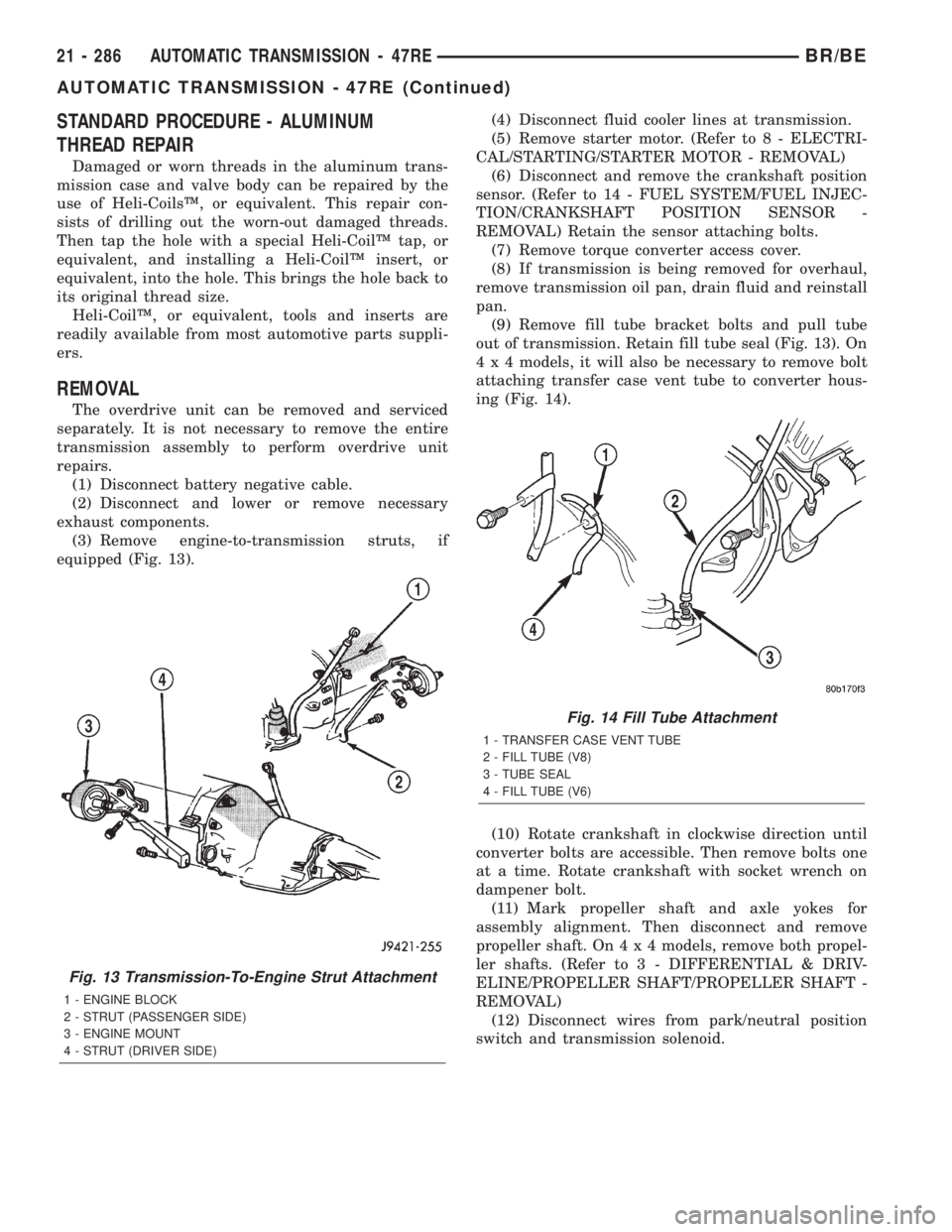
(3) Remove engine-to-transmission struts, if
equipped (Fig. 13).(4) Disconnect fluid cooler lines at transmission.
(5) Remove starter motor. (Refer to 8 - ELECTRI-
CAL/STARTING/STARTER MOTOR - REMOVAL)
(6) Disconnect and remove the crankshaft position
sensor. (Refer to 14 - FUEL SYSTEM/FUEL INJEC-
TION/CRANKSHAFT POSITION SENSOR -
REMOVAL) Retain the sensor attaching bolts.
(7) Remove torque converter access cover.
(8) If transmission is being removed for overhaul,
remove transmission oil pan, drain fluid and reinstall
pan.
(9) Remove fill tube bracket bolts and pull tube
out of transmission. Retain fill tube seal (Fig. 13). On
4 x 4 models, it will also be necessary to remove bolt
attaching transfer case vent tube to converter hous-
ing (Fig. 14).
(10) Rotate crankshaft in clockwise direction until
converter bolts are accessible. Then remove bolts one
at a time. Rotate crankshaft with socket wrench on
dampener bolt.
(11) Mark propeller shaft and axle yokes for
assembly alignment. Then disconnect and remove
propeller shaft. On4x4models, remove both propel-
ler shafts. (Refer to 3 - DIFFERENTIAL & DRIV-
ELINE/PROPELLER SHAFT/PROPELLER SHAFT -
REMOVAL)
(12) Disconnect wires from park/neutral position
switch and transmission solenoid.
Fig. 13 Transmission-To-Engine Strut Attachment
1 - ENGINE BLOCK
2 - STRUT (PASSENGER SIDE)
3 - ENGINE MOUNT
4 - STRUT (DRIVER SIDE)
Fig. 14 Fill Tube Attachment
1 - TRANSFER CASE VENT TUBE
2 - FILL TUBE (V8)
3 - TUBE SEAL
4 - FILL TUBE (V6)
21 - 286 AUTOMATIC TRANSMISSION - 47REBR/BE
AUTOMATIC TRANSMISSION - 47RE (Continued)
Page 1961 of 2255
TIRES
DESCRIPTION
DESCRIPTION - SPARE TIRE - TEMPORARY
The temporary spare tire is designed for emer-
gency use only. The original tire should be repaired
or replaced at the first opportunity, then reinstalled.
Do not exceed speeds of 50 M.P.H. when using the
temporary spare tire. Refer to Owner's Manual for
complete details.
DESCRIPTION - TIRES
Tires are designed and engineered for each specific
vehicle. They provide the best overall performance
for normal operation. The ride and handling charac-
teristics match the vehicle's requirements. With
proper care they will give excellent reliability, trac-
tion, skid resistance, and tread life.
Driving habits have more effect on tire life than
any other factor. Careful drivers will obtain in most
cases, much greater mileage than severe use or care-
less drivers. A few of the driving habits which will
shorten the life of any tire are:
²Rapid acceleration
²Severe brake applications
²High speed driving
²Excessive speeds on turns
²Striking curbs and other obstacles
Radial-ply tires are more prone to irregular tread
wear. It is important to follow the tire rotation inter-
val shown in the section on Tire Rotation, (Refer to
22 - TIRES/WHEELS - STANDARD PROCEDURE).
This will help to achieve a greater tread life.
TIRE IDENTIFICATION
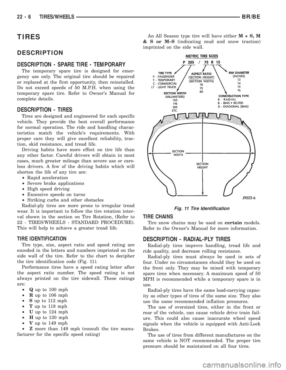
Tire type, size, aspect ratio and speed rating are
encoded in the letters and numbers imprinted on the
side wall of the tire. Refer to the chart to decipher
the tire identification code (Fig. 11).
Performance tires have a speed rating letter after
the aspect ratio number. The speed rating is not
always printed on the tire sidewall. These ratings
are:
²Qup to 100 mph
²Rup to 106 mph
²Sup to 112 mph
²Tup to 118 mph
²Uup to 124 mph
²Hup to 130 mph
²Vup to 149 mph
²Zmore than 149 mph (consult the tire manu-
facturer for the specific speed rating)An All Season type tire will have eitherM+S,M
&SorM±S(indicating mud and snow traction)
imprinted on the side wall.
TIRE CHAINS
Tire snow chains may be used oncertainmodels.
Refer to the Owner's Manual for more information.
DESCRIPTION - RADIAL-PLY TIRES
Radial-ply tires improve handling, tread life and
ride quality, and decrease rolling resistance.
Radial-ply tires must always be used in sets of
four. Under no circumstances should they be used on
the front only. They may be mixed with temporary
spare tires when necessary. A maximum speed of 50
MPH is recommended while a temporary spare is in
use.
Radial-ply tires have the same load-carrying capac-
ity as other types of tires of the same size. They also
use the same recommended inflation pressures.
The use of oversized tires, either in the front or
rear of the vehicle, can cause vehicle drive train fail-
ure. This could also cause inaccurate wheel speed
signals when the vehicle is equipped with Anti-Lock
Brakes.
The use of tires from different manufactures on the
same vehicle is NOT recommended. The proper tire
pressure should be maintained on all four tires.
Fig. 11 Tire Identification
22 - 6 TIRES/WHEELSBR/BE
Page 1962 of 2255
DESCRIPTION - TIRE PRESSURE FOR HIGH
SPEEDS
Where speed limits allow the vehicle to be driven
at high speeds, correct tire inflation pressure is very
important. For speeds up to and including 120 km/h
(75 mph), tires must be inflated to the pressures
shown on the tire placard. For continuous speeds in
excess of 120 km/h (75 mph), tires must be inflated
to the maximum pressure specified on the tire side-
wall.
Vehicles loaded to the maximum capacity should
not be driven at continuous speeds above 75 mph
(120 km/h).
For emergency vehicles that are driven at speeds
over 90 mph (144 km/h), special high speed tires
must be used. Consult tire manufacturer for correct
inflation pressure recommendations.
DESCRIPTION - REPLACEMENT TIRES
The original equipment tires provide a proper bal-
ance of many characteristics such as:
²Ride
²Noise
²Handling
²Durability
²Tread life
²Traction
²Rolling resistance
²Speed capability
It is recommended that tires equivalent to the orig-
inal equipment tires be used when replacement is
needed.
Failure to use equivalent replacement tires may
adversely affect the safety and handling of the vehi-
cle.
The use of oversize tires may cause interference
with vehicle components. Under extremes of suspen-
sion and steering travel, interference with vehicle
components may cause tire damage.
WARNING: FAILURE TO EQUIP THE VEHICLE WITH
TIRES HAVING ADEQUATE SPEED CAPABILITY
CAN RESULT IN SUDDEN TIRE FAILURE.
DESCRIPTION - TIRE INFLATION PRESSURES
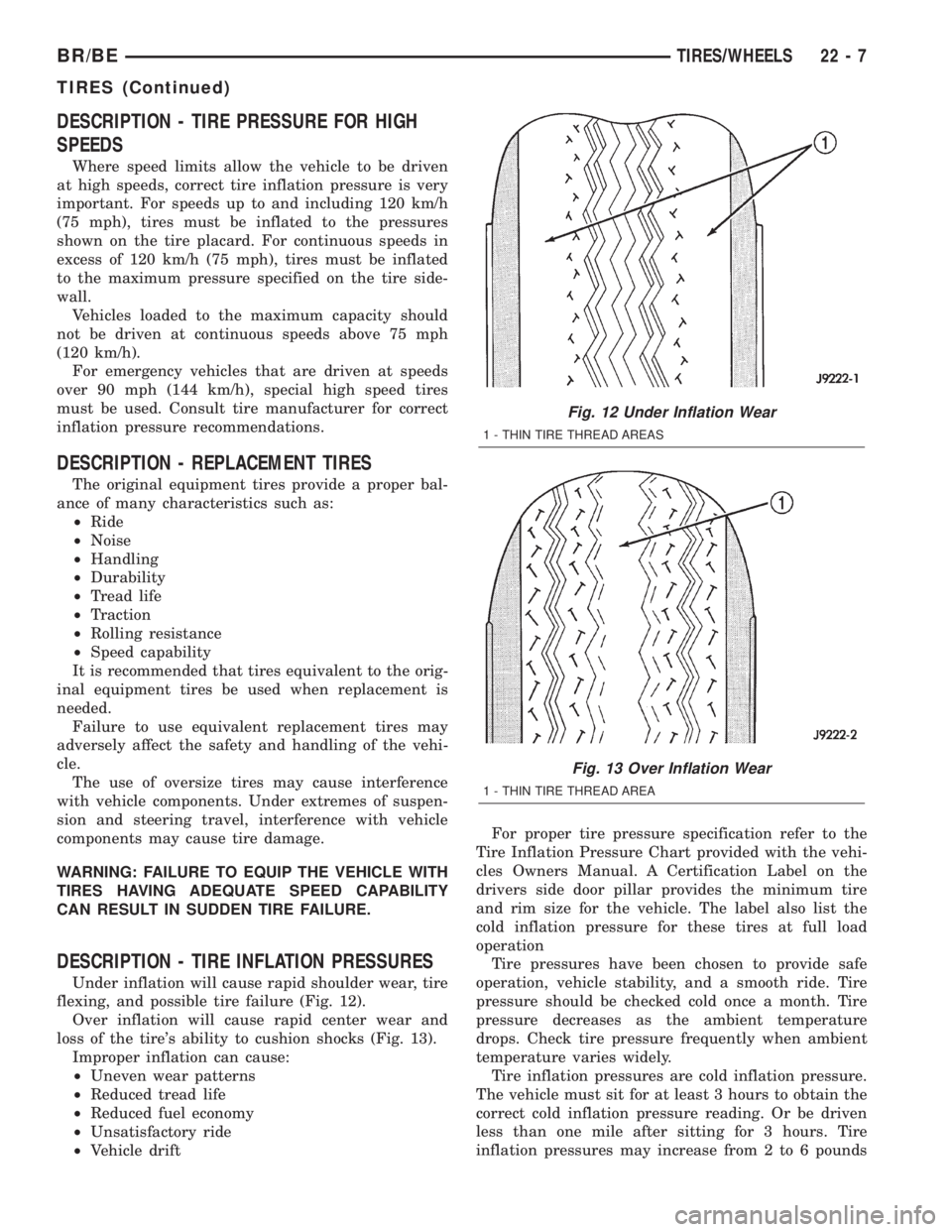
Under inflation will cause rapid shoulder wear, tire
flexing, and possible tire failure (Fig. 12).
Over inflation will cause rapid center wear and
loss of the tire's ability to cushion shocks (Fig. 13).
Improper inflation can cause:
²Uneven wear patterns
²Reduced tread life
²Reduced fuel economy
²Unsatisfactory ride
²Vehicle driftFor proper tire pressure specification refer to the
Tire Inflation Pressure Chart provided with the vehi-
cles Owners Manual. A Certification Label on the
drivers side door pillar provides the minimum tire
and rim size for the vehicle. The label also list the
cold inflation pressure for these tires at full load
operation
Tire pressures have been chosen to provide safe
operation, vehicle stability, and a smooth ride. Tire
pressure should be checked cold once a month. Tire
pressure decreases as the ambient temperature
drops. Check tire pressure frequently when ambient
temperature varies widely.
Tire inflation pressures are cold inflation pressure.
The vehicle must sit for at least 3 hours to obtain the
correct cold inflation pressure reading. Or be driven
less than one mile after sitting for 3 hours. Tire
inflation pressures may increase from 2 to 6 pounds
Fig. 12 Under Inflation Wear
1 - THIN TIRE THREAD AREAS
Fig. 13 Over Inflation Wear
1 - THIN TIRE THREAD AREA
BR/BETIRES/WHEELS 22 - 7
TIRES (Continued)
Page 1964 of 2255
DIAGNOSIS AND TESTING - TIRE NOISE OR
VIBRATION
Radial-ply tires are sensitive to force impulses
caused by improper mounting, vibration, wheel
defects, or possibly tire imbalance.
To find out if tires are causing the noise or vibra-
tion, drive the vehicle over a smooth road at varying
speeds. Note the noise level during acceleration and
deceleration. The engine, differential and exhaust
noises will change as speed varies, while the tire
noise will usually remain constant.
STANDARD PROCEDURE - REPAIRING LEAKS
For proper repairing, a radial tire must be removed
from the wheel. Repairs should only be made if the
defect, or puncture, is in the tread area (Fig. 16). The
tire should be replaced if the puncture is located in
the sidewall.
Deflate tire completely before removing the tire
from the wheel. Use lubrication such as a mild soap
solution when dismounting or mounting tire. Use
tools free of burrs or sharp edges which could dam-
age the tire or wheel rim.
Before mounting tire on wheel, make sure all rust
is removed from the rim bead and repaint if neces-
sary.Install wheel on vehicle, and tighten to proper
torque specification, (Refer to 22 - TIRES/WHEELS/
WHEELS - SPECIFICATIONS).
SPECIFICATIONS
TIRE REVOLUTIONS PER MILE
TIRE SIZE SUPPLIER REVOLUTIONS PER MILE
P225/75/R16 XL GOODYEAR 716
P245/75R16
WRT/SGOODYEAR 692
P245/75R16
LTX A/SMICHELIN 691
P265/75R16
WRT/SGOODYEAR 668
LT245/75R16 LTX A/S MICHELIN 679
LT245/75R16 LTX M/S MICHELIN 678
LT265/75R16 LTX A/S MICHELIN 648
LT265/75R16 LTX M/S MICHELIN 652
LT275/70R17
WGSAGOODYEAR 650
LT235/85R16
WAPGOODYEAR 650
LT235/85R16
LTX M/SMICHELIN 650
Fig. 16 Tire Repair Area
1 - REPAIRABLE AREA
BR/BETIRES/WHEELS 22 - 9
TIRES (Continued)
Page 2164 of 2255
CAUTION - REFRIGERANT HOSES/LINES/
TUBES PRECAUTIONS
Kinks or sharp bends in the refrigerant plumbing
will reduce the capacity of the entire system. High
pressures are produced in the system when it is oper-
ating. Extreme care must be exercised to make sure
that all refrigerant system connections are pressure
tight.
A good rule for the flexible hose refrigerant lines is
to keep the radius of all bends at least ten times the
diameter of the hose. Sharp bends will reduce the
flow of refrigerant. The flexible hose lines should be
routed so they are at least 80 millimeters (3 inches)
from the exhaust manifold. It is a good practice to
inspect all flexible refrigerant system hose lines at
least once a year to make sure they are in good con-
dition and properly routed.
There are two types of refrigerant fittings:
²All fittings with O-rings need to be coated with
refrigerant oil before installation. Use only O-rings
that are the correct size and approved for use with
R-134a refrigerant. Failure to do so may result in a
leak.
²Unified plumbing connections with gaskets can-
not be serviced with O-rings. The gaskets are not
reusable and new gaskets do not require lubrication
before installing.
Using the proper tools when making a refrigerant
plumbing connection is very important. Improper
tools or improper use of the tools can damage the
refrigerant fittings. Always use two wrenches when
loosening or tightening tube fittings. Use one wrench
to hold one side of the connection stationary, while
loosening or tightening the other side of the connec-
tion with a second wrench.
The refrigerant must be recovered completely from
the system before opening any fitting or connection.
Open the fittings with caution, even after the refrig-
erant has been recovered. If any pressure is noticed
as a fitting is loosened, tighten the fitting and
recover the refrigerant from the system again.
Do not discharge refrigerant into the atmosphere.
Use an R-134a refrigerant recovery/recycling device
that meets SAE Standard J2210.
The refrigerant system will remain chemically sta-
ble as long as pure, moisture-free R-134a refrigerant
and refrigerant oil is used. Dirt, moisture, or air can
upset this chemical stability. Operational troubles or
serious damage can occur if foreign material is
present in the refrigerant system.
When it is necessary to open the refrigerant sys-
tem, have everything needed to service the system
ready. The refrigerant system should not be left open
to the atmosphere any longer than necessary. Cap or
plug all lines and fittings as soon as they are opened
to prevent the entrance of dirt and moisture. All linesand components in parts stock should be capped or
sealed until they are to be installed.
All tools, including the refrigerant recycling equip-
ment, the manifold gauge set, and test hoses should
be kept clean and dry. All tools and equipment must
be designed for R-134a refrigerant.
DIAGNOSIS AND TESTING - REFRIGERANT
SYSTEM LEAKS
WARNING: (Refer to 24 - HEATING & AIR CONDI-
TIONING/PLUMBING - WARNING) (Refer to 24 -
HEATING & AIR CONDITIONING/PLUMBING - CAU-
TION) BEFORE PERFORMING THE FOLLOWING
OPERATION.
If the air conditioning system is not cooling prop-
erly, determine if the refrigerant system is fully-
charged. (Refer to 24 - HEATING & AIR
CONDITIONING - DIAGNOSIS AND TESTING -
A/C PERFORMANCE) If the refrigerant system is
low or empty; a leak at a refrigerant line, connector
fitting, component, or component seal is likely.
An electronic leak detector designed for R-134a
refrigerant, or a fluorescent R-134a leak detection
dye and a black light are recommended for locating
and confirming refrigerant system leaks. Refer to the
operating instructions supplied by the equipment
manufacturer for proper care and use of this equip-
ment.
An oily residue on or near refrigerant system lines,
connector fittings, components, or component seals
can indicate the general location of a possible refrig-
erant leak. However, the exact leak location should
be confirmed with an electronic leak detector prior to
component repair or replacement.
To detect a leak in the refrigerant system with an
electronic leak detector, perform one of the following
procedures:
SYSTEM EMPTY
(1) Evacuate the refrigerant system. (Refer to 24 -
HEATING & AIR CONDITIONING/PLUMBING -
STANDARD PROCEDURE - REFRIGERANT SYS-
TEM EVACUATE)
(2) Connect and dispense 0.283 kilograms (0.625
pounds or 10 ounces) of R-134a refrigerant into the
evacuated refrigerant system. (Refer to 24 - HEAT-
ING & AIR CONDITIONING/PLUMBING - STAN-
DARD PROCEDURE - REFRIGERANT SYSTEM
CHARGE)
(3) Position the vehicle in a wind-free work area.
This will aid in detecting small leaks.
(4) With the engine not running, use a electronic
R-134a leak detector and search for leaks. Because
R-134a refrigerant is heavier than air, the leak detec-
BR/BEPLUMBING 24 - 43
PLUMBING (Continued)