washer fluid DODGE RAM 2002 Service Repair Manual
[x] Cancel search | Manufacturer: DODGE, Model Year: 2002, Model line: RAM, Model: DODGE RAM 2002Pages: 2255, PDF Size: 62.07 MB
Page 102 of 2255
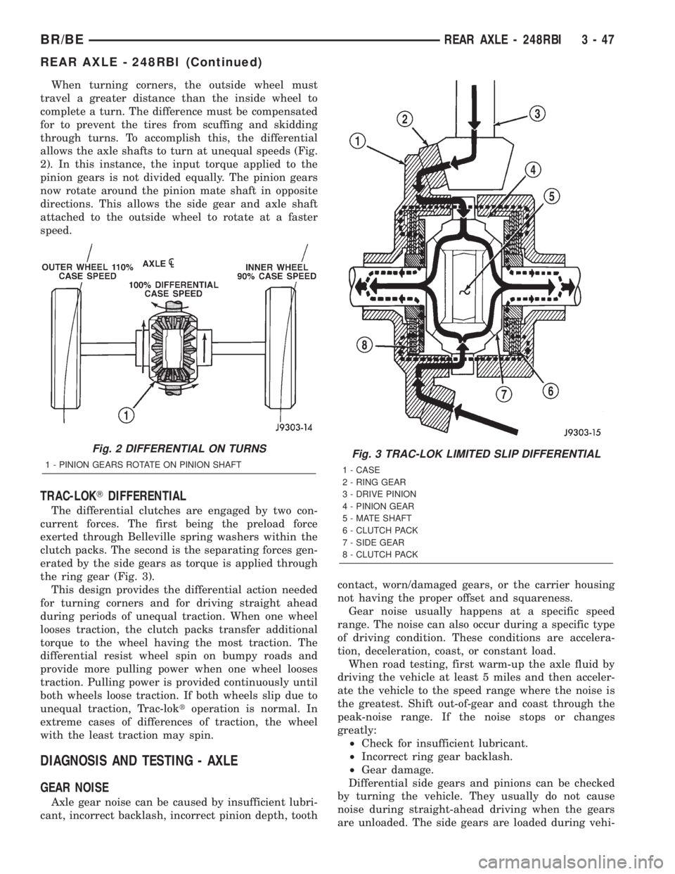
When turning corners, the outside wheel must
travel a greater distance than the inside wheel to
complete a turn. The difference must be compensated
for to prevent the tires from scuffing and skidding
through turns. To accomplish this, the differential
allows the axle shafts to turn at unequal speeds (Fig.
2). In this instance, the input torque applied to the
pinion gears is not divided equally. The pinion gears
now rotate around the pinion mate shaft in opposite
directions. This allows the side gear and axle shaft
attached to the outside wheel to rotate at a faster
speed.
TRAC-LOKTDIFFERENTIAL
The differential clutches are engaged by two con-
current forces. The first being the preload force
exerted through Belleville spring washers within the
clutch packs. The second is the separating forces gen-
erated by the side gears as torque is applied through
the ring gear (Fig. 3).
This design provides the differential action needed
for turning corners and for driving straight ahead
during periods of unequal traction. When one wheel
looses traction, the clutch packs transfer additional
torque to the wheel having the most traction. The
differential resist wheel spin on bumpy roads and
provide more pulling power when one wheel looses
traction. Pulling power is provided continuously until
both wheels loose traction. If both wheels slip due to
unequal traction, Trac-loktoperation is normal. In
extreme cases of differences of traction, the wheel
with the least traction may spin.
DIAGNOSIS AND TESTING - AXLE
GEAR NOISE
Axle gear noise can be caused by insufficient lubri-
cant, incorrect backlash, incorrect pinion depth, toothcontact, worn/damaged gears, or the carrier housing
not having the proper offset and squareness.
Gear noise usually happens at a specific speed
range. The noise can also occur during a specific type
of driving condition. These conditions are accelera-
tion, deceleration, coast, or constant load.
When road testing, first warm-up the axle fluid by
driving the vehicle at least 5 miles and then acceler-
ate the vehicle to the speed range where the noise is
the greatest. Shift out-of-gear and coast through the
peak-noise range. If the noise stops or changes
greatly:
²Check for insufficient lubricant.
²Incorrect ring gear backlash.
²Gear damage.
Differential side gears and pinions can be checked
by turning the vehicle. They usually do not cause
noise during straight-ahead driving when the gears
are unloaded. The side gears are loaded during vehi-
Fig. 2 DIFFERENTIAL ON TURNS
1 - PINION GEARS ROTATE ON PINION SHAFTFig. 3 TRAC-LOK LIMITED SLIP DIFFERENTIAL
1 - CASE
2 - RING GEAR
3 - DRIVE PINION
4 - PINION GEAR
5 - MATE SHAFT
6 - CLUTCH PACK
7 - SIDE GEAR
8 - CLUTCH PACK
BR/BEREAR AXLE - 248RBI 3 - 47
REAR AXLE - 248RBI (Continued)
Page 135 of 2255
torque supplied to the non-slipping wheel. The differ-
ential resist wheel spin on bumpy roads and provide
more pulling power when one wheel looses traction.
Pulling power is provided continuously until both
wheels loose traction. If both wheels slip due to
unequal traction, operation is normal. In extreme
cases of differences of traction, the wheel with the
least traction may spin.
DIAGNOSIS AND TESTING - AXLE
GEAR NOISE
Axle gear noise can be caused by insufficient lubri-
cant, incorrect backlash, incorrect pinion depth, tooth
contact, worn/damaged gears, or the carrier housing
not having the proper offset and squareness.
Gear noise usually happens at a specific speed
range. The noise can also occur during a specific type
of driving condition. These conditions are accelera-
tion, deceleration, coast, or constant load.
When road testing, first warm-up the axle fluid by
driving the vehicle at least 5 miles and then acceler-
ate the vehicle to the speed range where the noise is
the greatest. Shift out-of-gear and coast through the
peak-noise range. If the noise stops or changes
greatly:
²Check for insufficient lubricant.
²Incorrect ring gear backlash.
²Gear damage.
Differential side gears and pinions can be checked
by turning the vehicle. They usually do not cause
noise during straight-ahead driving when the gears
are unloaded. The side gears are loaded during vehi-
cle turns. A worn pinion shaft can also cause a snap-
ping or a knocking noise.
BEARING NOISE
The axle shaft, differential and pinion bearings can
all produce noise when worn or damaged. Bearing
noise can be either a whining, or a growling sound.
Pinion bearings have a constant-pitch noise. This
noise changes only with vehicle speed. Pinion bearing
noise will be higher pitched because it rotates at a
faster rate. Drive the vehicle and load the differen-
tial. If bearing noise occurs, the rear pinion bearing
is the source of the noise. If the bearing noise is
heard during a coast, the front pinion bearing is the
source.
Worn or damaged differential bearings usually pro-
duce a low pitch noise. Differential bearing noise is
similar to pinion bearing noise. The pitch of differen-
tial bearing noise is also constant and varies only
with vehicle speed.Axle shaft bearings produce noise and vibration
when worn or damaged. The noise generally changes
when the bearings are loaded. Road test the vehicle.
Turn the vehicle sharply to the left and to the right.
This will load the bearings and change the noise
level. Where axle bearing damage is slight, the noise
is usually not noticeable at speeds above 30 mph.
LOW SPEED KNOCK
Low speed knock is generally caused by a worn
U-joint or by worn side±gear thrust washers. A worn
pinion shaft bore will also cause low speed knock.
VIBRATION
Vibration at the rear of the vehicle is usually
caused by a:
²Damaged drive shaft.
²Missing drive shaft balance weight(s).
²Worn or out-of-balance wheels.
²Loose wheel lug nuts.
²Worn U-joint(s).
²Loose/broken springs.
²Damaged axle shaft bearing(s).
²Loose pinion gear nut.
²Excessive pinion yoke run out.
²Bent axle shaft(s).
Check for loose or damaged front-end components
or engine/transmission mounts. These components
can contribute to what appears to be a rearend vibra-
tion. Do not overlook engine accessories, brackets
and drive belts.
NOTE: All driveline components should be exam-
ined before starting any repair.
DRIVELINE SNAP
A snap or clunk noise when the vehicle is shifted
into gear (or the clutch engaged), can be caused by:
²High engine idle speed.
²Transmission shift operation.
²Loose engine/transmission/transfer case mounts.
²Worn U-joints.
²Loose spring mounts.
²Loose pinion gear nut and yoke.
²Excessive ring gear backlash.
²Excessive side gear to case clearance.
The source of a snap or a clunk noise can be deter-
mined with the assistance of a helper. Raise the vehi-
cle on a hoist with the wheels free to rotate. Instruct
the helper to shift the transmission into gear. Listen
for the noise, a mechanics stethoscope is helpful in
isolating the source of a noise.
3 - 80 REAR AXLE - 267RBIBR/BE
REAR AXLE - 267RBI (Continued)
Page 163 of 2255
OPERATION
STANDARD DIFFERENTIAL
The axle receives power from the transmission/
transfer case through the rear propeller shaft. The
rear propeller shaft is connected to the pinion gear
which rotates the differential through the gear mesh
with the ring gear bolted to the differential case. The
engine power is transmitted to the axle shafts
through the pinion mate and side gears. The side
gears are splined to the axle shafts.
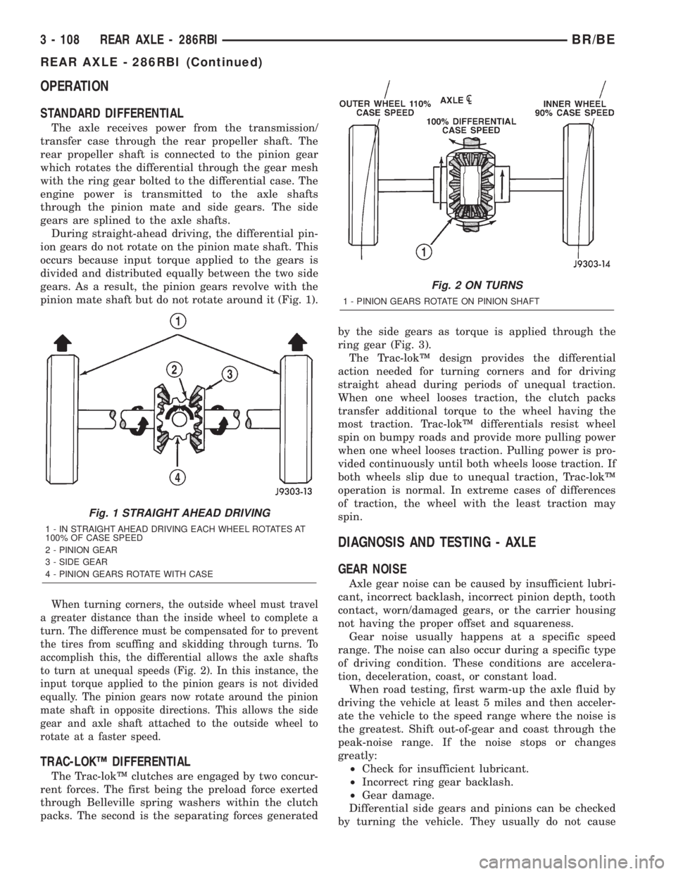
During straight-ahead driving, the differential pin-
ion gears do not rotate on the pinion mate shaft. This
occurs because input torque applied to the gears is
divided and distributed equally between the two side
gears. As a result, the pinion gears revolve with the
pinion mate shaft but do not rotate around it (Fig. 1).
When turning corners, the outside wheel must travel
a greater distance than the inside wheel to complete a
turn. The difference must be compensated for to prevent
the tires from scuffing and skidding through turns. To
accomplish this, the differential allows the axle shafts
to turn at unequal speeds (Fig. 2). In this instance, the
input torque applied to the pinion gears is not divided
equally. The pinion gears now rotate around the pinion
mate shaft in opposite directions. This allows the side
gear and axle shaft attached to the outside wheel to
rotate at a faster speed.
TRAC-LOKŸ DIFFERENTIAL
The Trac-lokŸ clutches are engaged by two concur-
rent forces. The first being the preload force exerted
through Belleville spring washers within the clutch
packs. The second is the separating forces generatedby the side gears as torque is applied through the
ring gear (Fig. 3).
The Trac-lokŸ design provides the differential
action needed for turning corners and for driving
straight ahead during periods of unequal traction.
When one wheel looses traction, the clutch packs
transfer additional torque to the wheel having the
most traction. Trac-lokŸ differentials resist wheel
spin on bumpy roads and provide more pulling power
when one wheel looses traction. Pulling power is pro-
vided continuously until both wheels loose traction. If
both wheels slip due to unequal traction, Trac-lokŸ
operation is normal. In extreme cases of differences
of traction, the wheel with the least traction may
spin.
DIAGNOSIS AND TESTING - AXLE
GEAR NOISE
Axle gear noise can be caused by insufficient lubri-
cant, incorrect backlash, incorrect pinion depth, tooth
contact, worn/damaged gears, or the carrier housing
not having the proper offset and squareness.
Gear noise usually happens at a specific speed
range. The noise can also occur during a specific type
of driving condition. These conditions are accelera-
tion, deceleration, coast, or constant load.
When road testing, first warm-up the axle fluid by
driving the vehicle at least 5 miles and then acceler-
ate the vehicle to the speed range where the noise is
the greatest. Shift out-of-gear and coast through the
peak-noise range. If the noise stops or changes
greatly:
²Check for insufficient lubricant.
²Incorrect ring gear backlash.
²Gear damage.
Differential side gears and pinions can be checked
by turning the vehicle. They usually do not cause
Fig. 1 STRAIGHT AHEAD DRIVING
1 - IN STRAIGHT AHEAD DRIVING EACH WHEEL ROTATES AT
100% OF CASE SPEED
2 - PINION GEAR
3 - SIDE GEAR
4 - PINION GEARS ROTATE WITH CASE
Fig. 2 ON TURNS
1 - PINION GEARS ROTATE ON PINION SHAFT
3 - 108 REAR AXLE - 286RBIBR/BE
REAR AXLE - 286RBI (Continued)
Page 199 of 2255
(3) Connect the pressure differential switch wire
connector.
(4) Bleed base brake system, (Refer to 5 -
BRAKES/HYDRAULIC/MECHANICAL - STAN-
DARD PROCEDURE).
DISC BRAKE CALIPERS
DESCRIPTION
The caliper is a one-piece casting. The piston bores
are located in the inboard side. A square-cut piston
seal is located in a machined groove in the cylinder
bore.
The caliper pistons dust boot prevents dirt, water
and road splash from entering the piston bore. The
boot is seated in a groove machined at the outer end
of the caliper piston. The boot retaining flange is
seated in a counterbore machined in the outer end of
the caliper piston bore.
Ventilated disc brake rotors are used for all appli-
cations. The rotors are serviceable and can be
machined to restore surface finish when necessary.
OPERATION
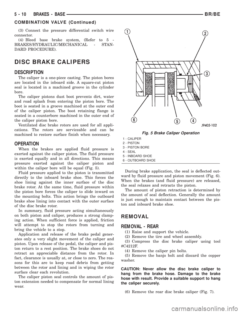
When the brakes are applied fluid pressure is
exerted against the caliper piston. The fluid pressure
is exerted equally and in all directions. This means
pressure exerted against the caliper piston and
within the caliper bore will be equal (Fig. 5).
Fluid pressure applied to the piston is transmitted
directly to the inboard brake shoe. This forces the
shoe lining against the inner surface of the disc
brake rotor. At the same time, fluid pressure within
the piston bore forces the caliper to slide inward on
the mounting bolts. This action brings the outboard
brake shoe lining into contact with the outer surface
of the disc brake rotor.
In summary, fluid pressure acting simultaneously
on both piston and caliper, produces a strong clamp-
ing action. When sufficient force is applied, friction
will attempt to stop the rotors from turning and
bring the vehicle to a stop.
Application and release of the brake pedal gener-
ates only a very slight movement of the caliper and
piston. Upon release of the pedal, the caliper and pis-
ton return to a rest position. The brake shoes do not
retract an appreciable distance from the rotor. In
fact, clearance is usually at, or close to zero. The rea-
sons for this are to keep road debris from getting
between the rotor and lining and in wiping the rotor
surface clear each revolution.
The caliper piston seal controls the amount of pis-
ton extension needed to compensate for normal lining
wear.During brake application, the seal is deflected out-
ward by fluid pressure and piston movement (Fig. 6).
When the brakes (and fluid pressure) are released,
the seal relaxes and retracts the piston.
The amount of piston retraction is determined by
the amount of seal deflection. Generally the amount
is just enough to maintain contact between the pis-
ton and inboard brake shoe.
REMOVAL
REMOVAL - REAR
(1) Raise and support the vehicle.
(2) Remove the tire and wheel assembly.
(3) Compress the disc brake caliper using tool
#C4212F.
(4) Remove the caliper pin bolts.
(5) Remove the banjo bolt and discard the copper
washer.
CAUTION: Never allow the disc brake caliper to
hang from the brake hose. Damage to the brake
hose with result. Provide a suitable support to hang
the caliper securely.
(6) Remove the rear disc brake caliper (Fig. 7).
Fig. 5 Brake Caliper Operation
1 - CALIPER
2 - PISTON
3 - PISTON BORE
4 - SEAL
5 - INBOARD SHOE
6 - OUTBOARD SHOE
5 - 10 BRAKES - BASEBR/BE
COMBINATION VALVE (Continued)
Page 200 of 2255
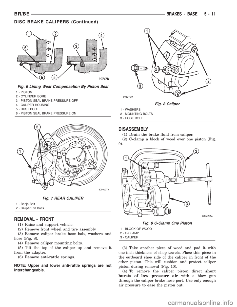
REMOVAL - FRONT
(1) Raise and support vehicle.
(2) Remove front wheel and tire assembly.
(3) Remove caliper brake hose bolt, washers and
hose (Fig. 8).
(4) Remove caliper mounting bolts.
(5) Tilt the top of the caliper up and remove it
from the adapter.
(6) Remove anti-rattle springs.
NOTE: Upper and lower anti-rattle springs are not
interchangeable.
DISASSEMBLY
(1) Drain the brake fluid from caliper.
(2) C-clamp a block of wood over one piston (Fig.
9).
(3) Take another piece of wood and pad it with
one-inch thickness of shop towels. Place this piece in
the outboard shoe side of the caliper in front of the
other piston. This will cushion and protect caliper
piston during removal (Fig. 10).
(4) To remove the caliper piston directshort
bursts of low pressure airwith a blow gun
through the caliper brake hose port. Use only enough
air pressure to ease the piston out.
Fig. 6 Lining Wear Compensation By Piston Seal
1 - PISTON
2 - CYLINDER BORE
3 - PISTON SEAL BRAKE PRESSURE OFF
4 - CALIPER HOUSING
5 - DUST BOOT
6 - PISTON SEAL BRAKE PRESSURE ON
Fig. 7 REAR CALIPER
1 - Banjo Bolt
2 - Caliper Pin Bolts
Fig. 8 Caliper
1 - WASHERS
2 - MOUNTING BOLTS
3 - HOSE BOLT
Fig. 9 C-Clamp One Piston
1 - BLOCK OF WOOD
2 - C-CLAMP
3 - CALIPER
BR/BEBRAKES - BASE 5 - 11
DISC BRAKE CALIPERS (Continued)
Page 208 of 2255
HYDRAULIC BOOSTER DIAGNOSIS CHART
CONDITION POSSIBLE CAUSES CORRECTION
Slow Brake Pedal Return 1. Excessive seal friction in booster. 1. Replace booster.
2. Faulty spool valve action. 2. Replace booster.
3. Restriction in booster return hose. 3. Replace hose.
4. Damaged input rod. 4. Replace booster.
Excessive Brake Pedal
Effort.1. Internal or external seal leakage. 1. Replace booster.
2. Faulty steering pump. 2. Replace pump.
Brakes Self Apply 1. Dump valve faulty. 1. Replace booster.
2. Contamination in hydraulic
system.2. Flush hydraulic system and replace
booster.
3. Restriction in booster return hose. 3. Replace hose.
Booster Chatter, Pedal
Vibration1. Slipping pump belt. 1. Replace power steering belt.
2. Low pump fluid level. 2. Fill pump and check for leaks.
Grabbing Brakes 1. Low pump flow. 1. Test and repair/replace pump.
2. Faulty spool valve action. 2. Replace booster.
STANDARD PROCEDURE - BLEEDING
The hydraulic booster is generally self-bleeding,
this procedure will normally bleed the air from the
booster. Normal driving and operation of the unit will
remove any remaining trapped air.
(1) Fill power steering pump reservoir.
(2) Disconnect fuel shutdown relay and crank the
engine for several seconds, Refer to Fuel System for
relay location and WARNING.
(3) Check fluid level and add if necessary.
(4) Connect fuel shutdown relay and start the
engine.
(5) Turn the steering wheel slowly from lock to
lock twice.
(6) Stop the engine and discharge the accumulator
by depressing the brake pedal 5 times.
(7) Start the engine and turn the steering wheel
slowly from lock to lock twice.
(8) Turn off the engine and check fluid level and
add if necessary.
NOTE: If fluid foaming occurs, wait for foam to dis-
sipate and repeat steps 7 and 8.
REMOVAL
NOTE: If the booster is being replaced because the
power steering fluid is contaminated, flush the
power steering system before replacing the booster.(1) With engine off depress the brake pedal 5
times to discharge the accumulator.
(2) Remove brake lines from master cylinder.
(3) Remove mounting nuts from the master cylin-
der.
(4) Remove the bracket from the hydraulic booster
lines and master cylinder mounting studs.
(5) Remove the master cylinder.
(6) Remove the return hose and the two pressure
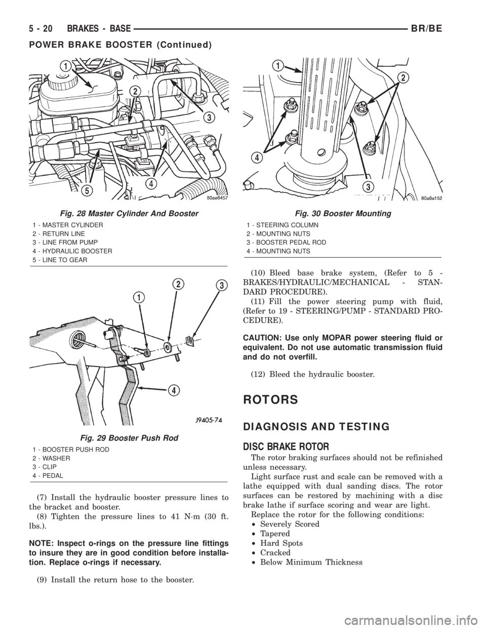
lines from the hydraulic booster (Fig. 28).
(7) Remove the booster push rod clip, washer and
rod remove from the brake pedal. (Fig. 29).
(8) Remove the mounting nuts from the hydraulic
booster and remove the booster (Fig. 30).
INSTALLATION
(1) Install the hydraulic booster and tighten the
mounting nuts to 28 N´m (21 ft. lbs.).
(2) Install the booster push rod, washer and clip
onto the brake pedal.
(3) Install the master cylinder on the mounting
studs. and tighten the mounting nuts to 23 N´m (17
ft. lbs.).
(4) Install the brake lines to the master cylinder
and tighten to 19-200 N´m (170-200 in. lbs.).
(5) Install the hydraulic booster line bracket onto
the master cylinder mounting studs.
(6) Install the master cylinder mounting nuts and
tighten to 23 N´m (17 ft. lbs.).
BR/BEBRAKES - BASE 5 - 19
POWER BRAKE BOOSTER (Continued)
Page 209 of 2255
(7) Install the hydraulic booster pressure lines to
the bracket and booster.
(8) Tighten the pressure lines to 41 N´m (30 ft.
lbs.).
NOTE: Inspect o-rings on the pressure line fittings
to insure they are in good condition before installa-
tion. Replace o-rings if necessary.
(9) Install the return hose to the booster.(10) Bleed base brake system, (Refer to 5 -
BRAKES/HYDRAULIC/MECHANICAL - STAN-
DARD PROCEDURE).
(11) Fill the power steering pump with fluid,
(Refer to 19 - STEERING/PUMP - STANDARD PRO-
CEDURE).
CAUTION: Use only MOPAR power steering fluid or
equivalent. Do not use automatic transmission fluid
and do not overfill.
(12) Bleed the hydraulic booster.
ROTORS
DIAGNOSIS AND TESTING
DISC BRAKE ROTOR
The rotor braking surfaces should not be refinished
unless necessary.
Light surface rust and scale can be removed with a
lathe equipped with dual sanding discs. The rotor
surfaces can be restored by machining with a disc
brake lathe if surface scoring and wear are light.
Replace the rotor for the following conditions:
²Severely Scored
²Tapered
²Hard Spots
²Cracked
²Below Minimum Thickness
Fig. 28 Master Cylinder And Booster
1 - MASTER CYLINDER
2 - RETURN LINE
3 - LINE FROM PUMP
4 - HYDRAULIC BOOSTER
5 - LINE TO GEAR
Fig. 29 Booster Push Rod
1 - BOOSTER PUSH ROD
2 - WASHER
3 - CLIP
4 - PEDAL
Fig. 30 Booster Mounting
1 - STEERING COLUMN
2 - MOUNTING NUTS
3 - BOOSTER PEDAL ROD
4 - MOUNTING NUTS
5 - 20 BRAKES - BASEBR/BE
POWER BRAKE BOOSTER (Continued)
Page 309 of 2255
INSPECTION
Inspect the radiator side tanks for cracks, broken
or missing fittings also inspect the joint where the
tanks seam up to the radiator core for signs of leak-
age and/or deteriorating seals.
Inspect radiator core for corroded, bent or missing
cooling fins. Inspect the core for bent or damaged
cooling tubes.
INSTALLATION
(1) Position fan shroud over the fan blades rear-
ward towards engine.
(2) Install rubber insulators to alignment dowels
at lower part of radiator.
(3) Lower the radiator into position while guiding
the two alignment dowels into lower radiator sup-
port. Different alignment holes are provided in the
lower radiator support for each engine application.
(4) Install two upper radiator mounting bolts.
Tighten bolts to 11 N´m (95 in. lbs.) torque.
(5) Position the rubber shields to the sides of radi-
ator. Install the plastic clips retaining the rubber
shields to the sides of radiator.
(6) Connect both radiator hoses and install hose
clamps.
(7) Install windshield washer reservoir tank.
(8) Position fan shroud to flanges on sides of radi-
ator. Install fan shroud mounting bolts (Fig. 34).
Tighten bolts to 6 N´m (50 in. lbs.) torque.
(9) Install coolant reserve/overflow tank hose to
radiator filler neck nipple.
(10) Install coolant reserve/overflow tank to fan
shroud (fits into T-slots on shroud).
(11) Install battery negative cables.
(12) Position heater controls tofull heatposition.
(13) Fill cooling system with coolant (Refer to 7 -
COOLING - STANDARD PROCEDURE).
(14) Operate engine until it reaches normal tem-
perature. Check cooling system fluid levels.
RADIATOR - 8.0L
DESCRIPTION
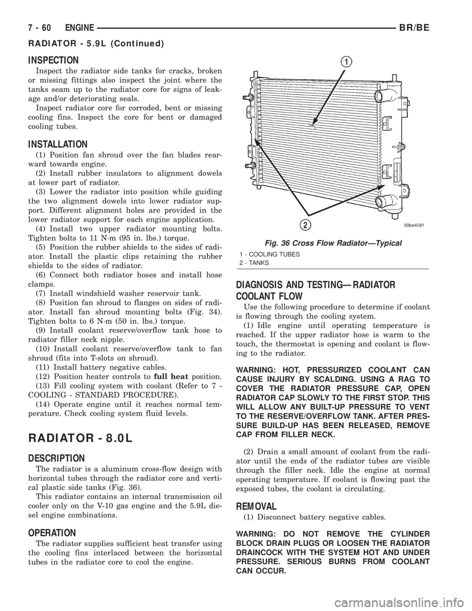
The radiator is a aluminum cross-flow design with
horizontal tubes through the radiator core and verti-
cal plastic side tanks (Fig. 36).
This radiator contains an internal transmission oil
cooler only on the V-10 gas engine and the 5.9L die-
sel engine combinations.
OPERATION
The radiator supplies sufficient heat transfer using
the cooling fins interlaced between the horizontal
tubes in the radiator core to cool the engine.
DIAGNOSIS AND TESTINGÐRADIATOR
COOLANT FLOW
Use the following procedure to determine if coolant
is flowing through the cooling system.
(1) Idle engine until operating temperature is
reached. If the upper radiator hose is warm to the
touch, the thermostat is opening and coolant is flow-
ing to the radiator.
WARNING: HOT, PRESSURIZED COOLANT CAN
CAUSE INJURY BY SCALDING. USING A RAG TO
COVER THE RADIATOR PRESSURE CAP, OPEN
RADIATOR CAP SLOWLY TO THE FIRST STOP. THIS
WILL ALLOW ANY BUILT-UP PRESSURE TO VENT
TO THE RESERVE/OVERFLOW TANK. AFTER PRES-
SURE BUILD-UP HAS BEEN RELEASED, REMOVE
CAP FROM FILLER NECK.
(2) Drain a small amount of coolant from the radi-
ator until the ends of the radiator tubes are visible
through the filler neck. Idle the engine at normal
operating temperature. If coolant is flowing past the
exposed tubes, the coolant is circulating.
REMOVAL
(1) Disconnect battery negative cables.
WARNING: DO NOT REMOVE THE CYLINDER
BLOCK DRAIN PLUGS OR LOOSEN THE RADIATOR
DRAINCOCK WITH THE SYSTEM HOT AND UNDER
PRESSURE. SERIOUS BURNS FROM COOLANT
CAN OCCUR.
Fig. 36 Cross Flow RadiatorÐTypical
1 - COOLING TUBES
2 - TANKS
7 - 60 ENGINEBR/BE
RADIATOR - 5.9L (Continued)
Page 311 of 2255
(2) Install rubber insulators to alignment dowels
at lower part of radiator.
(3) Lower the radiator into position while guiding
the two alignment dowels into lower radiator sup-
port. Different alignment holes are provided in the
lower radiator support for each engine application.
(4) Install two upper radiator mounting bolts.
Tighten bolts to 11 N´m (95 in. lbs.) torque.
(5) Connect both radiator hoses and install hose
clamps.
(6) Install windshield washer reservoir tank.
(7) Position fan shroud to flanges on sides of radi-
ator. Install fan shroud mounting bolts (Fig. 37).
Tighten bolts to 6 N´m (50 in. lbs.) torque.
(8) Install coolant reserve/overflow tank hose to
radiator filler neck nipple.
(9) Connect the overflow hose to the radiator.
(10) Install battery negative cables.
(11) Position heater controls tofull heatposition.
(12) Fill cooling system with coolant (Refer to 7 -
COOLING - STANDARD PROCEDURE).
(13) Operate engine until it reaches normal tem-
perature. Check cooling system fluid levels.
RADIATOR - 5.9L DIESEL
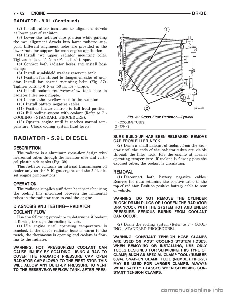
DESCRIPTION
The radiator is a aluminum cross-flow design with
horizontal tubes through the radiator core and verti-
cal plastic side tanks (Fig. 39).
This radiator contains an internal transmission oil
cooler only on the V-10 gas engine and the 5.9L die-
sel engine combinations.
OPERATION
The radiator supplies sufficient heat transfer using
the cooling fins interlaced between the horizontal
tubes in the radiator core to cool the engine.
DIAGNOSIS AND TESTINGÐRADIATOR
COOLANT FLOW
Use the following procedure to determine if coolant
is flowing through the cooling system.
(1) Idle engine until operating temperature is
reached. If the upper radiator hose is warm to the
touch, the thermostat is opening and coolant is flow-
ing to the radiator.
WARNING: HOT, PRESSURIZED COOLANT CAN
CAUSE INJURY BY SCALDING. USING A RAG TO
COVER THE RADIATOR PRESSURE CAP, OPEN
RADIATOR CAP SLOWLY TO THE FIRST STOP. THIS
WILL ALLOW ANY BUILT-UP PRESSURE TO VENT
TO THE RESERVE/OVERFLOW TANK. AFTER PRES-SURE BUILD-UP HAS BEEN RELEASED, REMOVE
CAP FROM FILLER NECK.
(2) Drain a small amount of coolant from the radi-
ator until the ends of the radiator tubes are visible
through the filler neck. Idle the engine at normal
operating temperature. If coolant is flowing past the
exposed tubes, the coolant is circulating.
REMOVAL
(1) Disconnect both battery negative cables.
Remove the nuts retaining the positive cable to the
top of radiator. Position positive battery cable to rear
of vehicle.
WARNING: DO NOT REMOVE THE CYLINDER
BLOCK DRAIN PLUGS OR LOOSEN THE RADIATOR
DRAINCOCK WITH THE SYSTEM HOT AND UNDER
PRESSURE. SERIOUS BURNS FROM COOLANT
CAN OCCUR.
(2) Drain the cooling system (Refer to 7 - COOL-
ING - STANDARD PROCEDURE).
WARNING: CONSTANT TENSION HOSE CLAMPS
ARE USED ON MOST COOLING SYSTEM HOSES.
WHEN REMOVING OR INSTALLING, USE ONLY
TOOLS DESIGNED FOR SERVICING THIS TYPE OF
CLAMP, SUCH AS SPECIAL CLAMP TOOL (NUMBER
6094). SNAP-ON CLAMP TOOL (NUMBER HPC-20)
MAY BE USED FOR LARGER CLAMPS. ALWAYS
WEAR SAFETY GLASSES WHEN SERVICING CON-
STANT TENSION CLAMPS.
Fig. 39 Cross Flow RadiatorÐTypical
1 - COOLING TUBES
2 - TANKS
7 - 62 ENGINEBR/BE
RADIATOR - 8.0L (Continued)
Page 313 of 2255
CLEANING
Clean radiator fins are necessary for good heat
transfer. The radiator and air conditioning fins
should be cleaned when an accumulation of debris
has occurred. With the engine cold, apply cold water
and compressed air to the back (engine side) of the
radiator to flush the radiator and/or A/C condenser of
debris.
INSPECTION
Inspect the radiator side tanks for cracks, broken
or missing fittings also inspect the joint where the
tanks seam up to the radiator core for signs of leak-
age and/or deteriorating seals.
Inspect radiator core for corroded, bent or missing
cooling fins. Inspect the core for bent or damaged
cooling tubes.
INSTALLATION
(1) Position fan shroud over the fan blades rear-
ward towards engine.
(2) Install rubber insulators to alignment dowels
at lower part of radiator.
(3) Lower the radiator into position while guiding
the two alignment dowels into lower radiator sup-
port. Different alignment holes are provided in the
lower radiator support for each engine application.
(4) Install two upper radiator mounting bolts.
Tighten bolts to 11 N´m (95 in. lbs.) torque.
(5) Connect both radiator hoses and install hose
clamps.
(6) Connect transmission cooler lines to radiator
tank. Inspect quick connect fittings for debris and
install until an audible ªclickº is heard. Pull apart to
verify connection.
(7) Install windshield washer reservoir tank.
(8) Position fan shroud to flanges on sides of radi-
ator. Install fan shroud mounting bolts (Fig. 41).
Tighten bolts to 6 N´m (50 in. lbs.) torque.
(9) Install metal clips to top of fan shroud.
(10) Install coolant reserve/overflow tank hose to
radiator filler neck nipple.
(11) Install coolant reserve/overflow tank to fan
shroud (fits into T-slots on shroud).
(12) Install battery negative cables.
(13) Install positive battery cable to top of radia-
tor. Tighten radiator-to-battery cable mounting nuts.
(14) Position heater controls tofull heatposition.
(15) Fill cooling system with coolant (Refer to 7 -
COOLING - STANDARD PROCEDURE).
(16) Operate engine until it reaches normal tem-
perature. Check cooling system and automatic trans-
mission (if equipped) fluid levels.
RADIATOR PRESSURE CAP
DESCRIPTION
Radiators are equipped with a pressure cap, which
releases pressure at some point within a range of
97-124 kPa (14-18 psi). The pressure relief point (in
pounds) is engraved on top of cap.
The cooling system will operate at pressures
slightly above atmospheric pressure. This results in a
higher coolant boiling point allowing increased radi-
ator cooling capacity.
A rubber gasket seals radiator filler neck to pre-
vent leakage. This is done to keep system under
pressure. It also maintains vacuum during coolant
cool-down allowing coolant to return from reserve/
overflow tank.
OPERATION
The cap (Fig. 43) contains a spring-loaded pressure
relief valve that opens when system pressure reaches
release range of 97-124 kPa (14-18 psi).
A vent valve in the center of cap allows a small
coolant flow through cap when coolant is below boil-
ing temperature. The valve is completely closed when
boiling point is reached. As the coolant cools, it con-
tracts and creates a vacuum in the cooling system.
This causes the vacuum valve to open and coolant in
the reserve/overflow tank to be drawn through its
connecting hose into radiator. If the vacuum valve is
stuck shut, the radiator hoses will collapse on cool-
down. Clean the vent valve (Fig. 43).
Fig. 43 Radiator Pressure Cap and Filler NeckÐ
Typical
1 - STAINLESS-STEEL SWIVEL TOP
2 - RUBBER SEALS
3 - VENT VALVE
4 - RADIATOR TANK
5 - FILLER NECK
6 - OVERFLOW NIPPLE
7 - MAIN SPRING
8 - GASKET RETAINER
7 - 64 ENGINEBR/BE
RADIATOR - 5.9L DIESEL (Continued)