compression ratio DODGE RAM 2003 Service User Guide
[x] Cancel search | Manufacturer: DODGE, Model Year: 2003, Model line: RAM, Model: DODGE RAM 2003Pages: 2895, PDF Size: 83.15 MB
Page 1347 of 2895
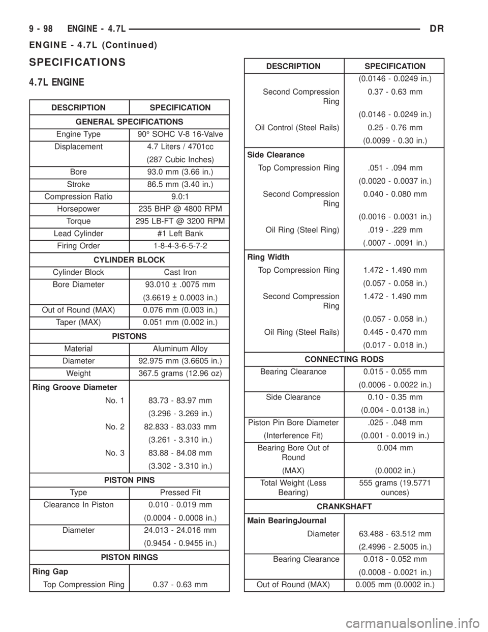
SPECIFICATIONS
4.7L ENGINE
DESCRIPTION SPECIFICATION
GENERAL SPECIFICATIONS
Engine Type 90É SOHC V-8 16-Valve
Displacement 4.7 Liters / 4701cc
(287 Cubic Inches)
Bore 93.0 mm (3.66 in.)
Stroke 86.5 mm (3.40 in.)
Compression Ratio 9.0:1
Horsepower 235 BHP @ 4800 RPM
Torque 295 LB-FT @ 3200 RPM
Lead Cylinder #1 Left Bank
Firing Order 1-8-4-3-6-5-7-2
CYLINDER BLOCK
Cylinder Block Cast Iron
Bore Diameter 93.010 .0075 mm
(3.6619 0.0003 in.)
Out of Round (MAX) 0.076 mm (0.003 in.)
Taper (MAX) 0.051 mm (0.002 in.)
PISTONS
Material Aluminum Alloy
Diameter 92.975 mm (3.6605 in.)
Weight 367.5 grams (12.96 oz)
Ring Groove Diameter
No. 1 83.73 - 83.97 mm
(3.296 - 3.269 in.)
No. 2 82.833 - 83.033 mm
(3.261 - 3.310 in.)
No. 3 83.88 - 84.08 mm
(3.302 - 3.310 in.)
PISTON PINS
Type Pressed Fit
Clearance In Piston 0.010 - 0.019 mm
(0.0004 - 0.0008 in.)
Diameter 24.013 - 24.016 mm
(0.9454 - 0.9455 in.)
PISTON RINGS
Ring Gap
Top Compression Ring 0.37 - 0.63 mm
DESCRIPTION SPECIFICATION
(0.0146 - 0.0249 in.)
Second Compression
Ring0.37 - 0.63 mm
(0.0146 - 0.0249 in.)
Oil Control (Steel Rails) 0.25 - 0.76 mm
(0.0099 - 0.30 in.)
Side Clearance
Top Compression Ring .051 - .094 mm
(0.0020 - 0.0037 in.)
Second Compression
Ring0.040 - 0.080 mm
(0.0016 - 0.0031 in.)
Oil Ring (Steel Ring) .019 - .229 mm
(.0007 - .0091 in.)
Ring Width
Top Compression Ring 1.472 - 1.490 mm
(0.057 - 0.058 in.)
Second Compression
Ring1.472 - 1.490 mm
(0.057 - 0.058 in.)
Oil Ring (Steel Rails) 0.445 - 0.470 mm
(0.017 - 0.018 in.)
CONNECTING RODS
Bearing Clearance 0.015 - 0.055 mm
(0.0006 - 0.0022 in.)
Side Clearance 0.10 - 0.35 mm
(0.004 - 0.0138 in.)
Piston Pin Bore Diameter .025 - .048 mm
(Interference Fit) (0.001 - 0.0019 in.)
Bearing Bore Out of
Round0.004 mm
(MAX) (0.0002 in.)
Total Weight (Less
Bearing)555 grams (19.5771
ounces)
CRANKSHAFT
Main BearingJournal
Diameter 63.488 - 63.512 mm
(2.4996 - 2.5005 in.)
Bearing Clearance 0.018 - 0.052 mm
(0.0008 - 0.0021 in.)
Out of Round (MAX) 0.005 mm (0.0002 in.)
9 - 98 ENGINE - 4.7LDR
ENGINE - 4.7L (Continued)
Page 1425 of 2895
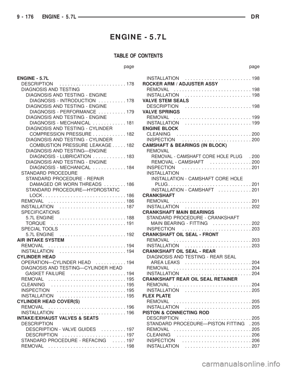
ENGINE - 5.7L
TABLE OF CONTENTS
page page
ENGINE - 5.7L
DESCRIPTION........................178
DIAGNOSIS AND TESTING
DIAGNOSIS AND TESTING - ENGINE
DIAGNOSIS - INTRODUCTION..........178
DIAGNOSIS AND TESTING - ENGINE
DIAGNOSIS - PERFORMANCE..........179
DIAGNOSIS AND TESTING - ENGINE
DIAGNOSIS - MECHANICAL............181
DIAGNOSIS AND TESTING - CYLINDER
COMPRESSION PRESSURE............182
DIAGNOSIS AND TESTING - CYLINDER
COMBUSTION PRESSURE LEAKAGE.....182
DIAGNOSIS AND TESTINGÐENGINE
DIAGNOSIS - LUBRICATION............183
DIAGNOSIS AND TESTING - ENGINE
DIAGNOSIS - MECHANICAL............184
STANDARD PROCEDURE
STANDARD PROCEDURE - REPAIR
DAMAGED OR WORN THREADS........186
STANDARD PROCEDUREÐHYDROSTATIC
LOCK..............................186
REMOVAL............................186
INSTALLATION........................187
SPECIFICATIONS
5.7L ENGINE........................188
TORQUE...........................191
SPECIAL TOOLS
5.7L ENGINE........................192
AIR INTAKE SYSTEM
REMOVAL............................194
INSTALLATION........................194
CYLINDER HEAD
OPERATIONÐCYLINDER HEAD...........194
DIAGNOSIS AND TESTINGÐCYLINDER HEAD
GASKET FAILURE....................194
REMOVAL............................195
CLEANING...........................195
INSPECTION.........................195
INSTALLATION........................195
CYLINDER HEAD COVER(S)
REMOVAL............................196
INSTALLATION........................196
INTAKE/EXHAUST VALVES & SEATS
DESCRIPTION
DESCRIPTION - VALVE GUIDES.........197
DESCRIPTION.......................197
STANDARD PROCEDURE - REFACING.....197
REMOVAL............................198INSTALLATION........................198
ROCKER ARM / ADJUSTER ASSY
REMOVAL............................198
INSTALLATION........................198
VALVE STEM SEALS
DESCRIPTION........................198
VALVE SPRINGS
REMOVAL............................199
INSTALLATION........................199
ENGINE BLOCK
CLEANING...........................200
INSPECTION.........................200
CAMSHAFT & BEARINGS (IN BLOCK)
REMOVAL
REMOVAL - CAMSHAFT CORE HOLE PLUG. 200
REMOVAL - CAMSHAFT...............200
INSPECTION.........................201
INSTALLATION
INSTALLATION - CAMSHAFT CORE HOLE
PLUG..............................201
INSTALLATION - CAMSHAFT............201
CRANKSHAFT
REMOVAL............................201
INSTALLATION........................202
CRANKSHAFT MAIN BEARINGS
STANDARD PROCEDURE - CRANKSHAFT
MAIN BEARING - FITTING..............202
INSPECTION.........................203
CRANKSHAFT OIL SEAL - FRONT
REMOVAL............................203
INSTALLATION........................203
CRANKSHAFT OIL SEAL - REAR
DIAGNOSIS AND TESTING - REAR SEAL
AREA LEAKS........................204
REMOVAL............................204
INSTALLATION........................204
CRANKSHAFT REAR OIL SEAL RETAINER
REMOVAL............................204
INSTALLATION........................205
FLEX PLATE
REMOVAL............................205
INSTALLATION........................205
PISTON & CONNECTING ROD
DESCRIPTION........................205
STANDARD PROCEDUREÐPISTON FITTING . 205
REMOVAL............................205
CLEANING...........................206
INSPECTION.........................206
INSTALLATION........................207
9 - 176 ENGINE - 5.7LDR
Page 1429 of 2895
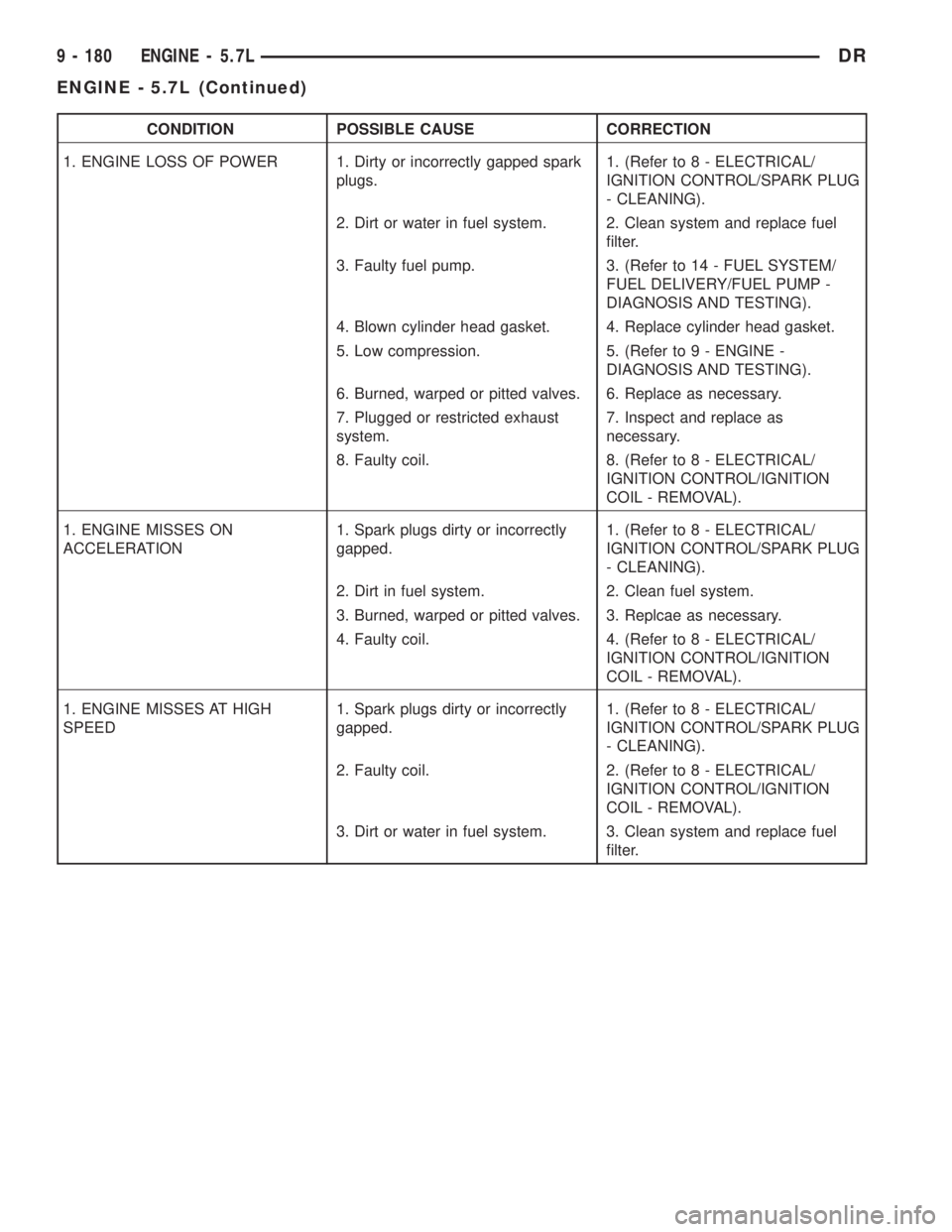
CONDITION POSSIBLE CAUSE CORRECTION
1. ENGINE LOSS OF POWER 1. Dirty or incorrectly gapped spark
plugs.1. (Refer to 8 - ELECTRICAL/
IGNITION CONTROL/SPARK PLUG
- CLEANING).
2. Dirt or water in fuel system. 2. Clean system and replace fuel
filter.
3. Faulty fuel pump. 3. (Refer to 14 - FUEL SYSTEM/
FUEL DELIVERY/FUEL PUMP -
DIAGNOSIS AND TESTING).
4. Blown cylinder head gasket. 4. Replace cylinder head gasket.
5. Low compression. 5. (Refer to 9 - ENGINE -
DIAGNOSIS AND TESTING).
6. Burned, warped or pitted valves. 6. Replace as necessary.
7. Plugged or restricted exhaust
system.7. Inspect and replace as
necessary.
8. Faulty coil. 8. (Refer to 8 - ELECTRICAL/
IGNITION CONTROL/IGNITION
COIL - REMOVAL).
1. ENGINE MISSES ON
ACCELERATION1. Spark plugs dirty or incorrectly
gapped.1. (Refer to 8 - ELECTRICAL/
IGNITION CONTROL/SPARK PLUG
- CLEANING).
2. Dirt in fuel system. 2. Clean fuel system.
3. Burned, warped or pitted valves. 3. Replcae as necessary.
4. Faulty coil. 4. (Refer to 8 - ELECTRICAL/
IGNITION CONTROL/IGNITION
COIL - REMOVAL).
1. ENGINE MISSES AT HIGH
SPEED1. Spark plugs dirty or incorrectly
gapped.1. (Refer to 8 - ELECTRICAL/
IGNITION CONTROL/SPARK PLUG
- CLEANING).
2. Faulty coil. 2. (Refer to 8 - ELECTRICAL/
IGNITION CONTROL/IGNITION
COIL - REMOVAL).
3. Dirt or water in fuel system. 3. Clean system and replace fuel
filter.
9 - 180 ENGINE - 5.7LDR
ENGINE - 5.7L (Continued)
Page 1437 of 2895
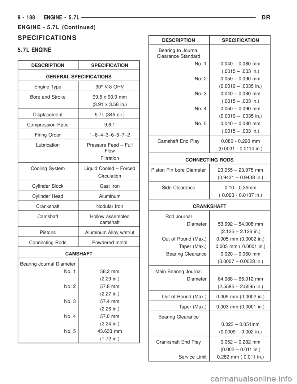
SPECIFICATIONS
5.7L ENGINE
DESCRIPTION SPECIFICATION
GENERAL SPECIFICATIONS
Engine Type 90É V-8 OHV
Bore and Stroke 99.5 x 90.9 mm
(3.91 x 3.58 in.)
Displacement 5.7L (345 c.i.)
Compression Ratio 9.6:1
Firing Order 1±8±4±3±6±5±7±2
Lubrication Pressure Feed ± Full
Flow
Filtration
Cooling System Liquid Cooled ± Forced
Circulation
Cylinder Block Cast Iron
Cylinder Head Aluminum
Crankshaft Nodular Iron
Camshaft Hollow assembled
camshaft
Pistons Aluminum Alloy w/strut
Connecting Rods Powdered metal
CAMSHAFT
Bearing Journal Diameter
No. 1 58.2 mm
(2.29 in.)
No. 2 57.8 mm
(2.27 in.)
No. 3 57.4 mm
(2.26 in.)
No. 4 57.0 mm
(2.24 in.)
No. 5 43.633 mm
(1.72 in.)
DESCRIPTION SPECIFICATION
Bearing to Journal
Clearance Standard
No. 1 0.040 ± 0.080 mm
(.0015 ± .003 in.)
No. 2 0.050 ± 0.090 mm
(0.0019 ± .0035 in.)
No. 3 0.040 ± 0.080 mm
(.0015 ± .003 in.)
No. 4 0.050 ± 0.090 mm
(0.0019 ± .0035 in.)
No. 5 0.040 ± 0.080 mm
(.0015 ± .003 in.)
Camshaft End Play 0.080 - 0.290 mm
(0.0031 - 0.0114 in.)
CONNECTING RODS
Piston Pin bore Diameter 23.955 ± 23.975 mm
(0.9431 ± 0.9438 in.)
Side Clearance 0.10 - 0.35mm
( 0.003 - 0.0137 in.)
CRANKSHAFT
Rod Journal
Diameter 53.992 ± 54.008 mm
(2.125 ± 2.126 in.)
Out of Round (Max.) 0.005 mm (0.0002 in.)
Taper (Max.) 0.003 mm ( 0.0001 in.)
Bearing Clearance 0.020 ± 0.060 mm
(0.0007 ± 0.0023 in.)
Main Bearing Journal
Diameter 64.988 ± 65.012 mm
(2.5585 ± 2.5595 in.)
Out of Round (Max.) 0.005 mm (0.0002 in.)
Taper (Max.) 0.003 mm (0.0001 in.)
Bearing Clearance
0.023 ± 0.051mm
(0.0009 ± 0.002 in.)
Crankshaft End Play 0.052 ± 0.282 mm
(0.002 ± 0.011 in.)
Service Limit 0.282 mm ( 0.011 in.)
9 - 188 ENGINE - 5.7LDR
ENGINE - 5.7L (Continued)
Page 1444 of 2895
þ Loss of engine power
þ Engine misfiring
þ Poor fuel economy
²Possible indications of the cylinder head gasket
leaking between a cylinder and an adjacent water
jacket are:
þ Engine overheating
þ Loss of coolant
þ Excessive steam (white smoke) emitting from
exhaust
þ Coolant foaming
CYLINDER-TO-CYLINDER LEAKAGE TEST
To determine if an engine cylinder head gasket is
leaking between adjacent cylinders, follow the proce-
dures in Cylinder Compression Pressure Test in this
section. An engine cylinder head gasket leaking
between adjacent cylinders will result in approxi-
mately a 50±70% reduction in compression pressure.
CYLINDER-TO-WATER JACKET LEAKAGE TEST
WARNING: USE EXTREME CAUTION WHEN THE
ENGINE IS OPERATING WITH COOLANT PRES-
SURE CAP REMOVED.
VISUAL TEST METHOD
With the engine cool, remove the coolant pressure
cap. Start the engine and allow it to warm up until
thermostat opens.
If a large combustion/compression pressure leak
exists, bubbles will be visible in the coolant.
COOLING SYSTEM TESTER METHOD
WARNING: WITH COOLING SYSTEM TESTER IN
PLACE, PRESSURE WILL BUILD UP FAST. EXCES-
SIVE PRESSURE BUILT UP, BY CONTINUOUS
ENGINE OPERATION, MUST BE RELEASED TO A
SAFE PRESSURE POINT. NEVER PERMIT PRES-
SURE TO EXCEED 138 kPa (20 psi).
Install Cooling System Tester 7700 or equivalent to
pressure cap neck. Start the engine and observe the
tester's pressure gauge. If gauge pulsates with every
power stroke of a cylinder a combustion pressure
leak is evident.
CHEMICAL TEST METHOD
Combustion leaks into the cooling system can also
be checked by using Bloc-Chek Kit C-3685-A or
equivalent. Perform test following the procedures
supplied with the tool kit.
REMOVAL
(1) Disconnect the battery negative cable.
(2) Drain cooling system.
(3) Remove the air cleaner resonator and duct
work.
(4) Remove the generator.
(5) Remove closed crankcase ventilation system.
(6) Disconnect the evaporation control system.
(7) Perform the Fuel System Pressure Release pro-
cedure (Refer to 14 - FUEL SYSTEM/FUEL DELIV-
ERY - STANDARD PROCEDURE). Disconnect the
fuel supply line (Refer to 14 - FUEL SYSTEM/FUEL
DELIVERY/QUICK CONNECT FITTING - STAN-
DARD PROCEDURE).
(8) Disconnect heater hoses.
(9) Remove cylinder head covers and gaskets.
(10) Remove intake manifold and throttle body as
an assembly.
(11) Remove rocker arm assemblies and push rods.
Identify to ensure installation in original locations.
(12) Remove the head bolts from each cylinder
head and remove cylinder heads. Discard the cylin-
der head gasket.
CLEANING
Clean all surfaces of cylinder block and cylinder
heads.
Clean cylinder block front and rear gasket surfaces
using a suitable solvent.
INSPECTION
(1) Inspect the cylinder head for out-of-flatness,
using a straightedge and a feeler gauge. If tolerances
exceed 0.0508 mm (0.002 in.) replace the cylinder
head.
(2) Inspect the valve seats for damage. Service the
valve seats as necessary.
(3) Inspect the valve guides for wear, cracks or
looseness. If either condition exist, replace the cylin-
der head.
(4) Inspect pushrods. Replace worn or bent push-
rods.
INSTALLATION
(1) Clean all surfaces of cylinder block and cylin-
der heads.
(2) Clean cylinder block front and rear gasket sur-
faces using a suitable solvent.
CAUTION: The head gaskets are not interchange-
able between left and right sides. They are marked
ªLº and ªRº to indicate left and right sides.
(3) Position new cylinder head gaskets onto the
cylinder block.
DRENGINE - 5.7L 9 - 195
CYLINDER HEAD (Continued)
Page 1472 of 2895
ENGINE - 5.9L
TABLE OF CONTENTS
page page
ENGINE - 5.9L
DESCRIPTION........................224
DIAGNOSIS AND TESTING
DIAGNOSIS AND TESTING - ENGINE
DIAGNOSIS - INTRODUCTION..........225
DIAGNOSIS AND TESTINGÐENGINE
DIAGNOSIS - PERFORMANCE..........226
DIAGNOSIS AND TESTING - ENGINE
DIAGNOSIS - MECHANICAL............228
DIAGNOSIS AND TESTINGÐENGINE
DIAGNOSIS - LUBRICATION............230
DIAGNOSIS AND TESTINGÐCYLINDER
COMPRESSION PRESSURE............231
DIAGNOSIS AND TESTING - CYLINDER
COMBUSTION PRESSURE LEAKAGE.....231
STANDARD PROCEDURE
STANDARD PROCEDURE - FORM-IN-
PLACE GASKETS AND SEALERS........232
STANDARD PROCEDURE - REPAIR
DAMAGED OR WORN THREADS........232
STANDARD PROCEDUREÐHYDROSTATIC
LOCK..............................232
STANDARD PROCEDURE - CYLINDER
BORE HONING......................233
REMOVAL............................233
INSTALLATION........................234
SPECIFICATIONS
5.9L ENGINE........................235
TORQUE...........................239
SPECIAL TOOLS
5.9L ENGINE........................240
AIR CLEANER ELEMENT
REMOVAL............................242
INSTALLATION........................242
CYLINDER HEAD
DESCRIPTION
DESCRIPTIONÐCYLINDER HEAD.......243
DESCRIPTION - CYLINDER HEAD COVER
GASKET...........................243
OPERATION
OPERATIONÐCYLINDER HEAD.........243
OPERATION - CYLINDER HEAD COVER
GASKET...........................243
DIAGNOSIS AND TESTINGÐCYLINDER HEAD
GASKET FAILURE....................243
REMOVAL............................244
CLEANING...........................244
INSPECTION.........................244
INSTALLATION........................244CYLINDER HEAD COVER(S)
REMOVAL............................245
CLEANING...........................245
INSPECTION.........................245
INSTALLATION........................245
INTAKE/EXHAUST VALVES & SEATS
DESCRIPTION........................246
STANDARD PROCEDUREÐVALVES, GUIDES
AND SPRINGS.......................246
REMOVAL............................248
CLEANING...........................248
INSPECTION.........................248
INSTALLATION........................248
ROCKER ARM / ADJUSTER ASSEMBLY
REMOVAL............................249
INSTALLATION........................249
ENGINE BLOCK
CLEANING...........................249
INSPECTION.........................249
CAMSHAFT & BEARINGS (IN BLOCK)
REMOVALÐCAMSHAFT.................250
INSTALLATIONÐCAMSHAFT.............250
CONNECTING ROD BEARINGS
STANDARD PROCEDURE - CONNECTING
ROD BEARING FITTING...............251
CRANKSHAFT
DESCRIPTION........................252
OPERATION..........................252
REMOVAL............................252
INSTALLATION........................252
CRANKSHAFT MAIN BEARINGS
DESCRIPTION........................253
OPERATION..........................253
STANDARD PROCEDUREÐCRANKSHAFT
MAIN BEARING FITTING...............253
REMOVAL............................254
INSTALLATION........................254
CRANKSHAFT OIL SEAL - FRONT
DESCRIPTION........................254
OPERATION..........................254
REMOVAL............................254
INSTALLATION........................255
CRANKSHAFT OIL SEAL - REAR
DESCRIPTION........................255
OPERATION..........................255
REMOVAL............................255
INSTALLATION........................256
DISTRIBUTOR BUSHING
REMOVAL............................258
INSTALLATION........................258
DRENGINE - 5.9L 9 - 223
Page 1484 of 2895
(19) Install the distributor cap and wiring.
(20) Install the intake manifold (Refer to 9 -
ENGINE/MANIFOLDS/INTAKE MANIFOLD -
INSTALLATION).
(21) Using a new gasket, install throttle body
(Refer to 14 - FUEL SYSTEM/FUEL INJECTION/
THROTTLE BODY - INSTALLATION).
(22) Connect the throttle linkage (Refer to 14 -
FUEL SYSTEM/FUEL INJECTION/THROTTLE
CONTROL CABLE - INSTALLATION).
(23) Install the air cleaner resonator and duct
work..
(24) Install the generator and wire connections
(Refer to 8 - ELECTRICAL/CHARGING/GENERA-
TOR - INSTALLATION).
(25) Install a/c compressor and lines (Refer to 24 -
HEATING & AIR CONDITIONING/PLUMBING/A/C
COMPRESSOR - INSTALLATION).
(26) Install the accessory drive belt (Refer to 7 -
COOLING/ACCESSORY DRIVE/DRIVE BELTS -
INSTALLATION).
(27) Install upper radiator support crossmember.
(28) Install radiator (Refer to 7 - COOLING/EN-
GINE/RADIATOR - INSTALLATION).
(29) Connect the radiator lower hose.
(30) Connect the transmission oil cooler lines to
the radiator.
(31) Install the fan shroud.
(32) Install the fan (Refer to 7 - COOLING/EN-
GINE/RADIATOR FAN - INSTALLATION).
(33) Connect the radiator upper hose.
(34) Install the washer bottle.
(35) Install the transmission oil cooler (Refer to 7 -
COOLING/TRANSMISSION/TRANS COOLER -
INSTALLATION).
(36) Connect the transmission cooler lines.
(37) If equipped, install the condenser (Refer to 24
- HEATING & AIR CONDITIONING/PLUMBING/
A/C CONDENSER - INSTALLATION).
(38) Evacuate and charge the air conditioning sys-
tem, if equipped (Refer to 24 - HEATING & AIR
CONDITIONING/PLUMBING - STANDARD PRO-
CEDURE).
(39) Add engine oil to crankcase (Refer to LUBRI-
CATION & MAINTENANCE/FLUID TYPES - SPEC-
IFICATIONS).
(40) Fill cooling system (Refer to 7 - COOLING -
STANDARD PROCEDURE).
(41) Connect battery negative cable.
(42) Start engine and inspect for leaks.
(43) Road test vehicle.SPECIFICATIONS
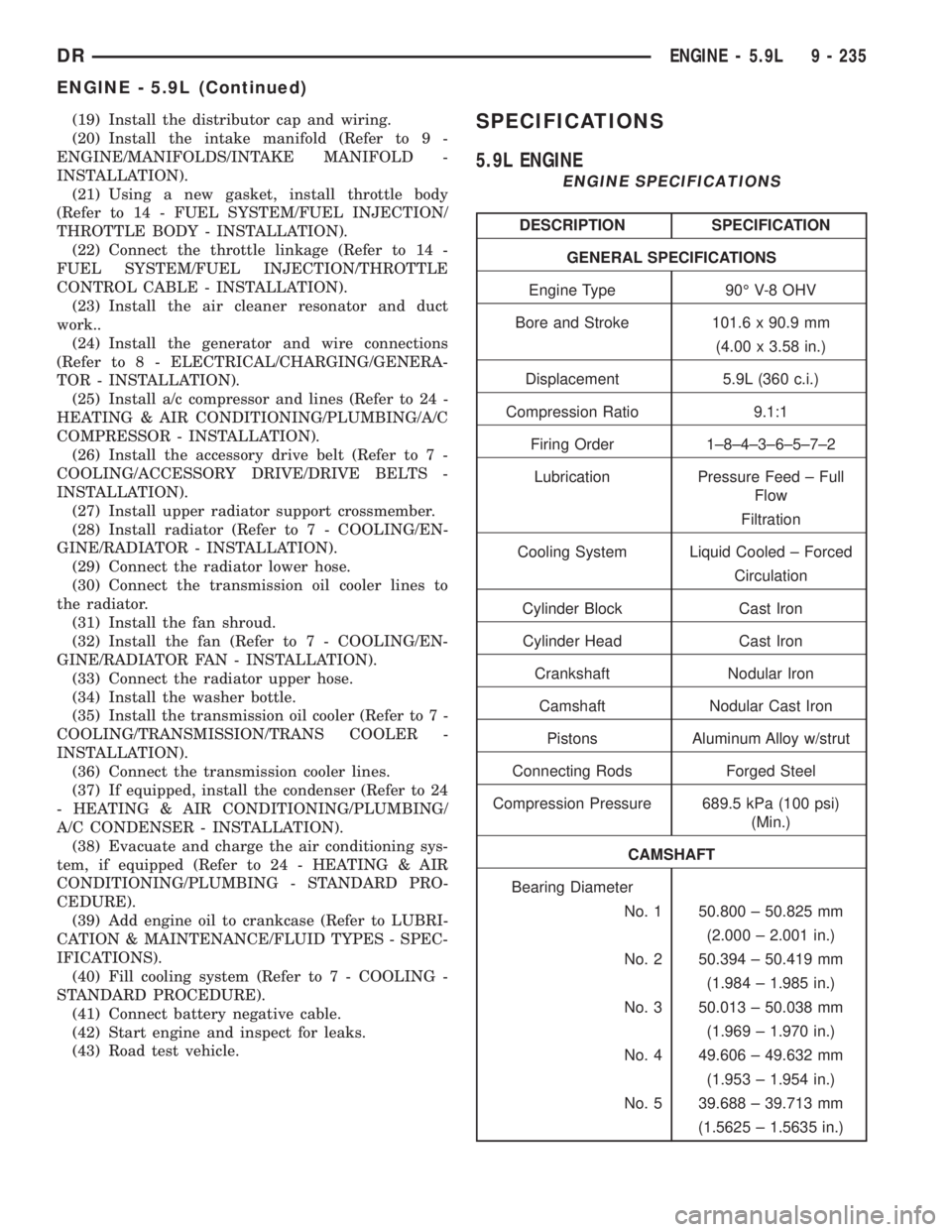
5.9L ENGINE
ENGINE SPECIFICATIONS
DESCRIPTION SPECIFICATION
GENERAL SPECIFICATIONS
Engine Type 90É V-8 OHV
Bore and Stroke 101.6 x 90.9 mm
(4.00 x 3.58 in.)
Displacement 5.9L (360 c.i.)
Compression Ratio 9.1:1
Firing Order 1±8±4±3±6±5±7±2
Lubrication Pressure Feed ± Full
Flow
Filtration
Cooling System Liquid Cooled ± Forced
Circulation
Cylinder Block Cast Iron
Cylinder Head Cast Iron
Crankshaft Nodular Iron
Camshaft Nodular Cast Iron
Pistons Aluminum Alloy w/strut
Connecting Rods Forged Steel
Compression Pressure 689.5 kPa (100 psi)
(Min.)
CAMSHAFT
Bearing Diameter
No. 1 50.800 ± 50.825 mm
(2.000 ± 2.001 in.)
No. 2 50.394 ± 50.419 mm
(1.984 ± 1.985 in.)
No. 3 50.013 ± 50.038 mm
(1.969 ± 1.970 in.)
No. 4 49.606 ± 49.632 mm
(1.953 ± 1.954 in.)
No. 5 39.688 ± 39.713 mm
(1.5625 ± 1.5635 in.)
DRENGINE - 5.9L 9 - 235
ENGINE - 5.9L (Continued)
Page 1487 of 2895
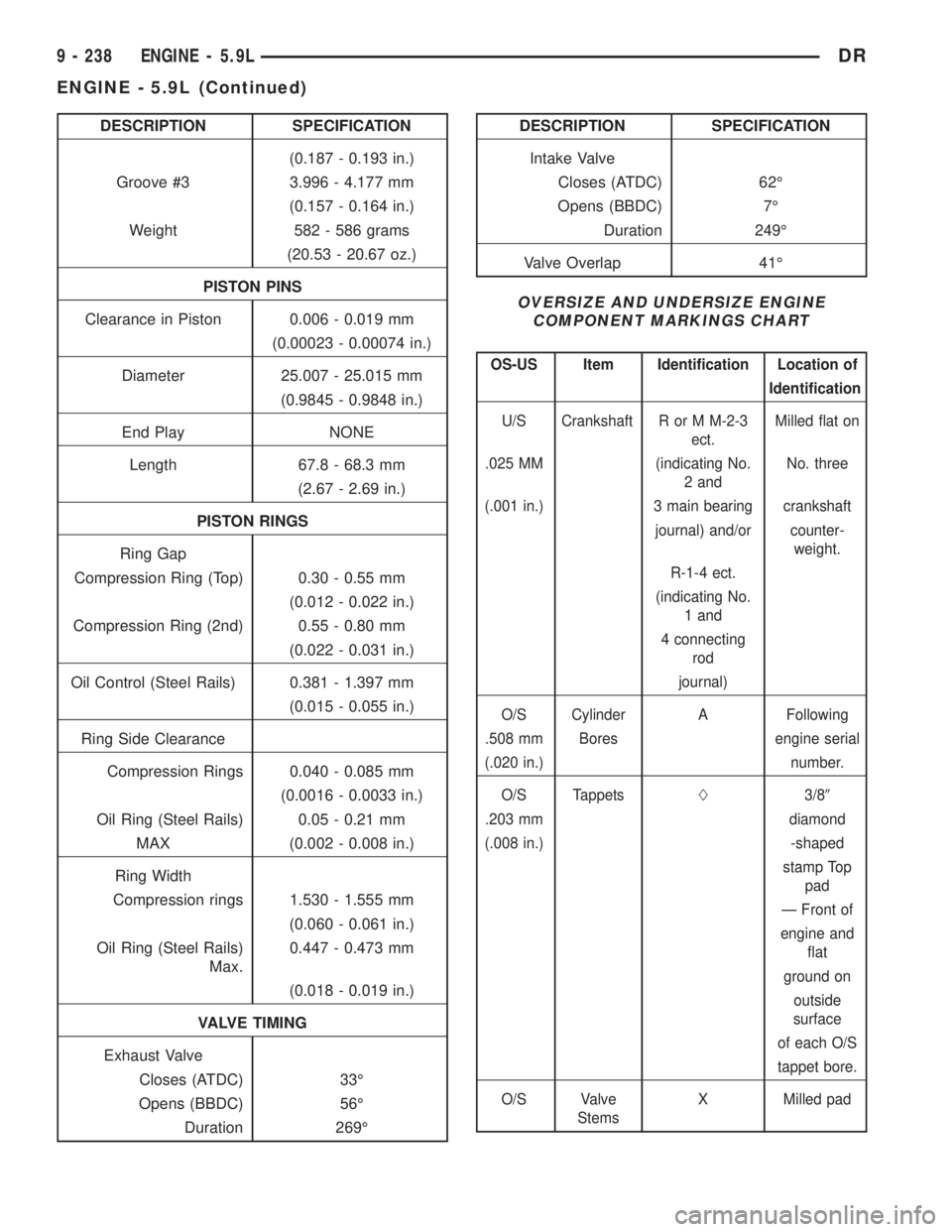
DESCRIPTION SPECIFICATION
(0.187 - 0.193 in.)
Groove #3 3.996 - 4.177 mm
(0.157 - 0.164 in.)
Weight 582 - 586 grams
(20.53 - 20.67 oz.)
PISTON PINS
Clearance in Piston 0.006 - 0.019 mm
(0.00023 - 0.00074 in.)
Diameter 25.007 - 25.015 mm
(0.9845 - 0.9848 in.)
End Play NONE
Length 67.8 - 68.3 mm
(2.67 - 2.69 in.)
PISTON RINGS
Ring Gap
Compression Ring (Top) 0.30 - 0.55 mm
(0.012 - 0.022 in.)
Compression Ring (2nd) 0.55 - 0.80 mm
(0.022 - 0.031 in.)
Oil Control (Steel Rails) 0.381 - 1.397 mm
(0.015 - 0.055 in.)
Ring Side Clearance
Compression Rings 0.040 - 0.085 mm
(0.0016 - 0.0033 in.)
Oil Ring (Steel Rails) 0.05 - 0.21 mm
MAX (0.002 - 0.008 in.)
Ring Width
Compression rings 1.530 - 1.555 mm
(0.060 - 0.061 in.)
Oil Ring (Steel Rails)
Max.0.447 - 0.473 mm
(0.018 - 0.019 in.)
VALVE TIMING
Exhaust Valve
Closes (ATDC) 33É
Opens (BBDC) 56É
Duration 269ÉDESCRIPTION SPECIFICATION
Intake Valve
Closes (ATDC) 62É
Opens (BBDC) 7É
Duration 249É
Valve Overlap 41É
OVERSIZE AND UNDERSIZE ENGINE
COMPONENT MARKINGS CHART
OS-US Item Identification Location of
Identification
U/S Crankshaft R or M M-2-3
ect.Milled flat on
.025 MM (indicating No.
2 andNo. three
(.001 in.) 3 main bearing crankshaft
journal) and/or counter-
weight.
R-1-4 ect.
(indicating No.
1 and
4 connecting
rod
journal)
O/S Cylinder A Following
.508 mm Bores engine serial
(.020 in.) number.
O/S TappetsL3/89
.203 mm diamond
(.008 in.) -shaped
stamp Top
pad
Ð Front of
engine and
flat
ground on
outside
surface
of each O/S
tappet bore.
O/S Valve
StemsX Milled pad
9 - 238 ENGINE - 5.9LDR
ENGINE - 5.9L (Continued)
Page 1492 of 2895
CYLINDER HEAD
DESCRIPTION
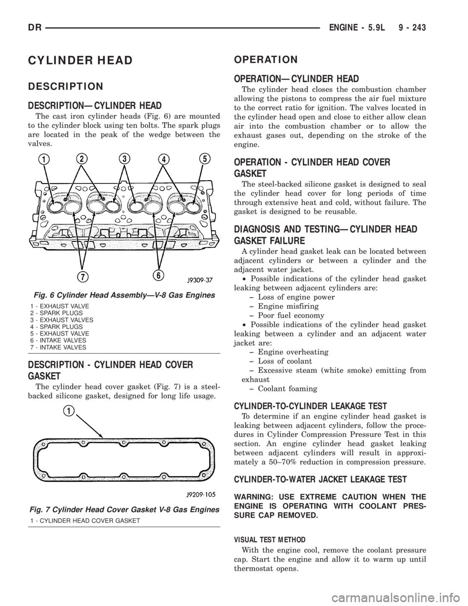
DESCRIPTIONÐCYLINDER HEAD
The cast iron cylinder heads (Fig. 6) are mounted
to the cylinder block using ten bolts. The spark plugs
are located in the peak of the wedge between the
valves.
DESCRIPTION - CYLINDER HEAD COVER
GASKET
The cylinder head cover gasket (Fig. 7) is a steel-
backed silicone gasket, designed for long life usage.
OPERATION
OPERATIONÐCYLINDER HEAD
The cylinder head closes the combustion chamber
allowing the pistons to compress the air fuel mixture
to the correct ratio for ignition. The valves located in
the cylinder head open and close to either allow clean
air into the combustion chamber or to allow the
exhaust gases out, depending on the stroke of the
engine.
OPERATION - CYLINDER HEAD COVER
GASKET
The steel-backed silicone gasket is designed to seal
the cylinder head cover for long periods of time
through extensive heat and cold, without failure. The
gasket is designed to be reusable.
DIAGNOSIS AND TESTINGÐCYLINDER HEAD
GASKET FAILURE
A cylinder head gasket leak can be located between
adjacent cylinders or between a cylinder and the
adjacent water jacket.
²Possible indications of the cylinder head gasket
leaking between adjacent cylinders are:
þ Loss of engine power
þ Engine misfiring
þ Poor fuel economy
²Possible indications of the cylinder head gasket
leaking between a cylinder and an adjacent water
jacket are:
þ Engine overheating
þ Loss of coolant
þ Excessive steam (white smoke) emitting from
exhaust
þ Coolant foaming
CYLINDER-TO-CYLINDER LEAKAGE TEST
To determine if an engine cylinder head gasket is
leaking between adjacent cylinders, follow the proce-
dures in Cylinder Compression Pressure Test in this
section. An engine cylinder head gasket leaking
between adjacent cylinders will result in approxi-
mately a 50±70% reduction in compression pressure.
CYLINDER-TO-WATER JACKET LEAKAGE TEST
WARNING: USE EXTREME CAUTION WHEN THE
ENGINE IS OPERATING WITH COOLANT PRES-
SURE CAP REMOVED.
VISUAL TEST METHOD
With the engine cool, remove the coolant pressure
cap. Start the engine and allow it to warm up until
thermostat opens.
Fig. 6 Cylinder Head AssemblyÐV-8 Gas Engines
1 - EXHAUST VALVE
2 - SPARK PLUGS
3 - EXHAUST VALVES
4 - SPARK PLUGS
5 - EXHAUST VALVE
6 - INTAKE VALVES
7 - INTAKE VALVES
Fig. 7 Cylinder Head Cover Gasket V-8 Gas Engines
1 - CYLINDER HEAD COVER GASKET
DRENGINE - 5.9L 9 - 243
Page 1493 of 2895
If a large combustion/compression pressure leak
exists, bubbles will be visible in the coolant.
COOLING SYSTEM TESTER METHOD
WARNING: WITH COOLING SYSTEM TESTER IN
PLACE, PRESSURE WILL BUILD UP FAST. EXCES-
SIVE PRESSURE BUILT UP, BY CONTINUOUS
ENGINE OPERATION, MUST BE RELEASED TO A
SAFE PRESSURE POINT. NEVER PERMIT PRES-
SURE TO EXCEED 138 kPa (20 psi).
Install Cooling System Tester 7700 or equivalent to
pressure cap neck. Start the engine and observe the
tester's pressure gauge. If gauge pulsates with every
power stroke of a cylinder a combustion pressure
leak is evident.
CHEMICAL TEST METHOD
Combustion leaks into the cooling system can also
be checked by using Bloc-Chek Kit C-3685-A or
equivalent. Perform test following the procedures
supplied with the tool kit.
REMOVAL
(1) Disconnect the battery negative cable.
(2) Drain cooling system (Refer to 7 - COOLING -
STANDARD PROCEDURE).
(3) Remove the air cleaner resonator and duct
work.
(4) Remove the intake manifold-to-generator
bracket support rod. Remove the generator.
(5) Remove closed crankcase ventilation system.
(6) Disconnect the evaporation control system.
(7) Perform the Fuel System Pressure Release pro-
cedure (Refer to 14 - FUEL SYSTEM/FUEL DELIV-
ERY - STANDARD PROCEDURE). Disconnect the
fuel supply line (Refer to 14 - FUEL SYSTEM/FUEL
DELIVERY/QUICK CONNECT FITTING - STAN-
DARD PROCEDURE).
(8) Disconnect accelerator linkage and if so
equipped, the speed control and transmission kick-
down cables.
(9) Remove distributor cap and wires.
(10) Disconnect the coil wires.
(11) Disconnect heat indicator sending unit wire.
(12) Disconnect heater hoses and bypass hose.
(13) Remove the master cylinder and booster
assembly. Refer to section 5 brakes.
(14) Remove cylinder head covers and gaskets
(Refer to 9 - ENGINE/CYLINDER HEAD/CYLIN-
DER HEAD COVER(S) - REMOVAL).
(15) Remove intake manifold (Refer to 9 -
ENGINE/MANIFOLDS/INTAKE MANIFOLD -
REMOVAL) and throttle body as an assembly. Dis-
card the flange side gaskets and the front and rear
cross-over gaskets.(16) Remove exhaust manifolds (Refer to 9 -
ENGINE/MANIFOLDS/EXHAUST MANIFOLD -
REMOVAL).
(17) Remove rocker arm assemblies and push rods.
Identify to ensure installation in original locations.
(18) Remove the head bolts from each cylinder
head and remove cylinder heads. Discard the cylin-
der head gasket.
(19) Remove spark plugs.
CLEANING
Clean all surfaces of cylinder block and cylinder
heads.
Clean cylinder block front and rear gasket surfaces
using a suitable solvent.
INSPECTION
Inspect all surfaces with a straightedge if there is
any reason to suspect leakage. If out-of-flatness
exceeds 0.00075mm/mm (0.0001in/in.) times the span
length in any direction, either replace head or lightly
machine the head surface.
FOR EXAMPLE:ÐA 305 mm (12 in.) span is
0.102 mm (0.004 in.) out-of-flat. The allowable out-of-
flat is 305 x 0.00075 (12 x 0.00075) equals 0.23 mm
(0.009 in.). This amount of out-of-flat is acceptable.
The cylinder head surface finish should be
1.78-3.00 microns (70-125 microinches).
Inspect push rods. Replace worn or bent rods.
INSTALLATION
(1) Clean all surfaces of cylinder block and cylin-
der heads.
(2) Clean cylinder block front and rear gasket sur-
faces using a suitable solvent.
(3) Position new cylinder head gaskets onto the
cylinder block.
(4) Position cylinder heads onto head gaskets and
cylinder block.
(5) Starting at top center, tighten all cylinder head
bolts, in sequence (Fig. 8).
CAUTION: When tightening the rocker arm bolts,
make sure the piston in that cylinder is NOT at
TDC. Contact between the valves and piston could
occur.
(6) Install push rods and rocker arm assemblies in
their original position. Tighten the bolts to 28 N´m
(21 ft. lbs.) torque.
(7) Install the intake manifold (Refer to 9 -
ENGINE/MANIFOLDS/INTAKE MANIFOLD -
INSTALLATION) and throttle body assembly.
(8) Install exhaust manifolds (Refer to 9 -
ENGINE/MANIFOLDS/EXHAUST MANIFOLD -
INSTALLATION).
9 - 244 ENGINE - 5.9LDR
CYLINDER HEAD (Continued)