brake sensor DODGE RAM 2003 Service Owner's Manual
[x] Cancel search | Manufacturer: DODGE, Model Year: 2003, Model line: RAM, Model: DODGE RAM 2003Pages: 2895, PDF Size: 83.15 MB
Page 269 of 2895
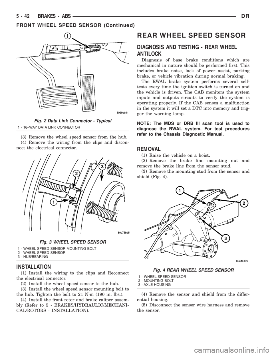
(3) Remove the wheel speed sensor from the hub.
(4) Remove the wiring from the clips and discon-
nect the electrical connector.
INSTALLATION
(1) Install the wiring to the clips and Reconnect
the electrical connector.
(2) Install the wheel speed sensor to the hub.
(3) Install the wheel speed sensor mounting bolt to
the hub. Tighten the bolt to 21 N´m (190 in. lbs.).
(4) Install the front rotor and brake caliper assem-
bly (Refer to 5 - BRAKES/HYDRAULIC/MECHANI-
CAL/ROTORS - INSTALLATION).
REAR WHEEL SPEED SENSOR
DIAGNOSIS AND TESTING - REAR WHEEL
ANTILOCK
Diagnosis of base brake conditions which are
mechanical in nature should be performed first. This
includes brake noise, lack of power assist, parking
brake, or vehicle vibration during normal braking.
The RWAL brake system performs several self-
tests every time the ignition switch is turned on and
the vehicle is driven. The CAB monitors the system
inputs and outputs circuits to verify the system is
operating properly. If the CAB senses a malfunction
in the system it will set a DTC into memory and trig-
ger the warning lamp.
NOTE: The MDS or DRB III scan tool is used to
diagnose the RWAL system. For test procedures
refer to the Chassis Diagnostic Manual.
REMOVAL
(1) Raise the vehicle on a hoist.
(2) Remove the brake line mounting nut and
remove the brake line from the sensor stud.
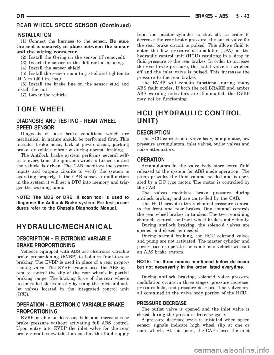
(3) Remove the mounting stud from the sensor and
shield (Fig. 4).
(4) Remove the sensor and shield from the differ-
ential housing.
(5) Disconnect the sensor wire harness and remove
the sensor.
Fig. 2 Data Link Connector - Typical
1 - 16±WAY DATA LINK CONNECTOR
Fig. 3 WHEEL SPEED SENSOR
1 - WHEEL SPEED SENSOR MOUNTING BOLT
2 - WHEEL SPEED SENSOR
3 - HUB/BEARING
Fig. 4 REAR WHEEL SPEED SENSOR
1 - WHEEL SPEED SENSOR
2 - MOUNTING BOLT
3 - AXLE HOUSING
5 - 42 BRAKES - ABSDR
FRONT WHEEL SPEED SENSOR (Continued)
Page 270 of 2895
INSTALLATION
(1) Connect the harness to the sensor.Be sure
the seal is securely in place between the sensor
and the wiring connector.
(2) Install the O-ring on the sensor (if removed).
(3) Insert the sensor in the differential housing.
(4) Install the sensor shield.
(5) Install the sensor mounting stud and tighten to
24 N´m (200 in. lbs.).
(6) Install the brake line on the sensor stud and
install the nut.
(7) Lower the vehicle.
TONE WHEEL
DIAGNOSIS AND TESTING - REAR WHEEL
SPEED SENSOR
Diagnosis of base brake conditions which are
mechanical in nature should be performed first. This
includes brake noise, lack of power assist, parking
brake, or vehicle vibration during normal braking.
The Antilock brake system performs several self-
tests every time the ignition switch is turned on and
the vehicle is driven. The CAB monitors the system
inputs and outputs circuits to verify the system is
operating properly. If the CAB senses a malfunction
in the system it will set a DTC into memory and trig-
ger the warning lamp.
NOTE: The MDS or DRB III scan tool is used to
diagnose the Antilock Brake system. For test proce-
dures refer to the Chassis Diagnostic Manual.
HYDRAULIC/MECHANICAL
DESCRIPTION - ELECTRONIC VARIABLE
BRAKE PROPORTIONING
Vehicles equipped with ABS use electronic variable
brake proportioning (EVBP) to balance front-to-rear
braking. The EVBP is used in place of a rear propor-
tioning valve. The EVBP system uses the ABS sys-
tem to control the slip of the rear wheels in partial
braking range. The braking force of the rear wheels
is controlled electronically by using the inlet and out-
let valves located in the integrated control unit
(ICU).
OPERATION - ELECTRONIC VARIABLE BRAKE
PROPORTIONING
EVBP is able to decrease, hold and increase rear
brake pressure without activating full ABS control.
Upon entry into EVBP the inlet valve for the rear
brake circuit is switched on so that the fluid supplyfrom the master cylinder is shut off. In order to
decrease the rear brake pressure, the outlet valve for
the rear brake circuit is pulsed. This allows fluid to
enter the low pressure accumulator (LPA) in the
hydraulic control unit (HCU) resulting in a drop in
fluid pressure to the rear brakes. In order to increase
the rear brake pressure, the outlet valve is switched
off and the inlet valve is pulsed. This increases the
pressure to the rear brakes.
The EVBP will remain functional during many
ABS fault modes. If both the red BRAKE and amber
ABS warning indicators are illuminated, the EVBP
may not be functioning.
HCU (HYDRAULIC CONTROL
UNIT)
DESCRIPTION
The HCU consists of a valve body, pump motor, low
pressure accumulators, inlet valves, outlet valves and
noise attenuators.
OPERATION
Accumulators in the valve body store extra fluid
released to the system for ABS mode operation. The
pump provides the fluid volume needed and is oper-
ated by a DC type motor. The motor is controlled by
the CAB.
The valves modulate brake pressure during
antilock braking and are controlled by the CAB.
The HCU provides three channel pressure control
to the front and rear brakes. One channel controls
the rear wheel brakes in tandem. The two remaining
channels control the front wheel brakes individually.
During antilock braking, the solenoid valves are
opened and closed as needed.
During normal braking, the HCU solenoid valves
and pump are not activated. The master cylinder and
power booster operate the same as a vehicle without
an ABS brake system.
NOTE: The three modes mentioned below do occur
but not necessarily in the order listed everytime.
During antilock braking, solenoid valve pressure
modulation occurs in three stages, pressure increase,
pressure hold, and pressure decrease. The valves are
all contained in the valve body portion of the HCU.
PRESSURE DECREASE
The outlet valve is opened and the inlet valve is
closed during the pressure decrease cycle.
A pressure decrease cycle is initiated when speed
sensor signals indicate high wheel slip at one or
more wheels. At this point, the CAB closes the inlet
DRBRAKES - ABS 5 - 43
REAR WHEEL SPEED SENSOR (Continued)
Page 271 of 2895
then opens the outlet valve, which also opens the
return circuit to the accumulators. Fluid pressure is
allowed to bleed off (decrease) as needed to prevent
wheel lock.
Once the period of high wheel slip has ended, the
CAB closes the outlet valve and begins a pressure
increase or hold cycle as needed.
PRESSURE HOLD
Both solenoid valves are closed in the pressure
hold cycle but only the inlet valve is energized. Fluid
apply pressure in the control channel is maintained
at a constant rate. The CAB maintains the hold cycle
until sensor inputs indicate a pressure change is nec-
essary.
PRESSURE INCREASE
The inlet valve is open and the outlet valve is
closed during the pressure increase cycle. The pres-
sure increase cycle is used to reapply thew brakes.
This cycle controls re-application of fluid apply pres-
sure.
REMOVAL
(1) Install a prop rod on the brake pedal to keep
pressure on the brake system.
(2) Disconnect the battery cables from the battery.
(3) Remove the battery.
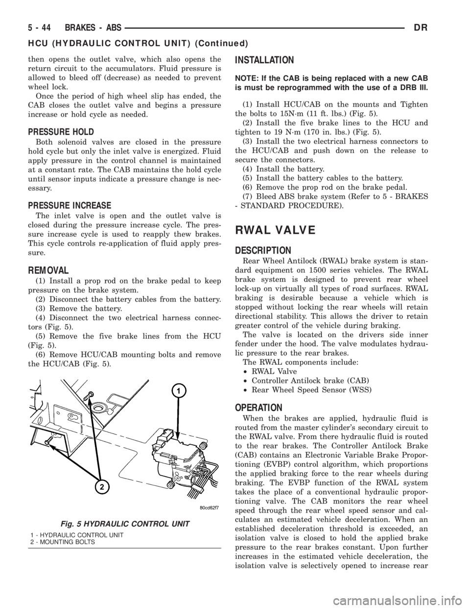
(4) Disconnect the two electrical harness connec-
tors (Fig. 5).
(5) Remove the five brake lines from the HCU
(Fig. 5).
(6) Remove HCU/CAB mounting bolts and remove
the HCU/CAB (Fig. 5).
INSTALLATION
NOTE: If the CAB is being replaced with a new CAB
is must be reprogrammed with the use of a DRB III.
(1) Install HCU/CAB on the mounts and Tighten
the bolts to 15N´m (11 ft. lbs.) (Fig. 5).
(2) Install the five brake lines to the HCU and
tighten to 19 N´m (170 in. lbs.) (Fig. 5).
(3) Install the two electrical harness connectors to
the HCU/CAB and push down on the release to
secure the connectors.
(4) Install the battery.
(5) Install the battery cables to the battery.
(6) Remove the prop rod on the brake pedal.
(7) Bleed ABS brake system (Refer to 5 - BRAKES
- STANDARD PROCEDURE).
RWAL VALVE
DESCRIPTION
Rear Wheel Antilock (RWAL) brake system is stan-
dard equipment on 1500 series vehicles. The RWAL
brake system is designed to prevent rear wheel
lock-up on virtually all types of road surfaces. RWAL
braking is desirable because a vehicle which is
stopped without locking the rear wheels will retain
directional stability. This allows the driver to retain
greater control of the vehicle during braking.
The valve is located on the drivers side inner
fender under the hood. The valve modulates hydrau-
lic pressure to the rear brakes.
The RWAL components include:
²RWAL Valve
²Controller Antilock brake (CAB)
²Rear Wheel Speed Sensor (WSS)
OPERATION
When the brakes are applied, hydraulic fluid is
routed from the master cylinder's secondary circuit to
the RWAL valve. From there hydraulic fluid is routed
to the rear brakes. The Controller Antilock Brake
(CAB) contains an Electronic Variable Brake Propor-
tioning (EVBP) control algorithm, which proportions
the applied braking force to the rear wheels during
braking. The EVBP function of the RWAL system
takes the place of a conventional hydraulic propor-
tioning valve. The CAB monitors the rear wheel
speed through the rear wheel speed sensor and cal-
culates an estimated vehicle deceleration. When an
established deceleration threshold is exceeded, an
isolation valve is closed to hold the applied brake
pressure to the rear brakes constant. Upon further
increases in the estimated vehicle deceleration, the
isolation valve is selectively opened to increase rear
Fig. 5 HYDRAULIC CONTROL UNIT
1 - HYDRAULIC CONTROL UNIT
2 - MOUNTING BOLTS
5 - 44 BRAKES - ABSDR
HCU (HYDRAULIC CONTROL UNIT) (Continued)
Page 295 of 2895
CONDITION POSSIBLE CAUSES CORRECTION
TEMPERATURE GAUGE READS
HIGH. COOLANT MAY OR MAY
NOT BE LEAKING FROM
SYSTEMNOTE:
Information on dash cluster is
displayed based on broadcast data
from ECM. DTC will be set for
engine sensor circuit concern.1. Vehicle overloaded, high ambient
(outside) temperatures with A/C
turned on, stop and go driving or
prolonged operation at idle speeds.1. Temporary condition, repair not
required. Notify customer of vehicle
operation instructions located in
Owners Manual.
2. Temperature gauge not
functioning correctly.2. Check cluster (Refer to 8 -
ELECTRICAL/INSTRUMENT
CLUSTER - DIAGNOSIS AND
TESTING)
3. Air trapped in cooling system 3. Drain cooling system (Refer to 7 -
COOLING - STANDARD
PROCEDURE) and refill (Refer to 7
- COOLING - STANDARD
PROCEDURE)
4. Radiator cap faulty. 4. Replace radiator cap.
5. Plugged A/C or radiator cooling
fins.5. Clean all debris away from A/C
and radiator cooling fins.
6. Coolant mixture incorrect. 6. Drain cooling system (Refer to 7 -
COOLING - STANDARD
PROCEDURE) refill with correct
mixture (Refer to 7 - COOLING -
STANDARD PROCEDURE).
7. Thermostat stuck shut. 7. Inspect and test thermostat.
Replace thermostat if necessary.
8. Bug screen or winter front being
used.8. Remove bug screen or winter
front.
9. Electronically controlled viscous
fan drive not operating properly.9. Check viscous fan (Refer to 7 -
COOLING/ENGINE/FAN DRIVE
VISCOUS CLUTCH - DIAGNOSIS
AND TESTING)
10. Cylinder head gasket leaking. 10. Check for leaking head gaskets
(Refer to 7 - COOLING -
DIAGNOSIS AND TESTING).
11. Heater core leaking. 11. Replace heater core.
12. Cooling system hoses leaking. 12. Tighten clamps or Replace
hoses.
13. Brakes dragging. 13. Check brakes. (Refer to 5 -
BRAKES/HYDRAULIC/
MECHANICAL - DIAGNOSIS AND
TESTING)
14. Accessory drive belt. 14. Inspect. Replace as necessary.
15. Water Pump. 15. Inspect and replace as
necessary.
7 - 8 COOLINGDR
COOLING (Continued)
Page 382 of 2895
ELECTRONIC CONTROL MODULES
TABLE OF CONTENTS
page page
COMMUNICATION
DESCRIPTION..........................1
OPERATION............................2
CONTROLLER ANTILOCK BRAKE
DESCRIPTION..........................3
OPERATION............................3
REMOVAL.............................3
INSTALLATION..........................3
DATA LINK CONNECTOR
DESCRIPTION - DATA LINK CONNECTOR.....3
OPERATION - DATA LINK CONNECTOR......3
ENGINE CONTROL MODULE
DESCRIPTION - ECM.....................4
OPERATION - ECM......................4
REMOVAL.............................4
INSTALLATION..........................5
FRONT CONTROL MODULE
DESCRIPTION..........................5
OPERATION............................5
DIAGNOSIS AND TESTING - FRONT
CONTROL MODULE....................6
REMOVAL.............................6
INSTALLATION..........................6
HEATED SEAT MODULE
DESCRIPTION..........................6
OPERATION............................6
DIAGNOSIS AND TESTING - HEATED SEAT
MODULE.............................7
REMOVAL.............................7
INSTALLATION..........................7
POWERTRAIN CONTROL MODULE
DESCRIPTION
DESCRIPTION - PCM...................8DESCRIPTION - MODES OF OPERATION....8
DESCRIPTION - 5 VOLT SUPPLIES.......10
DESCRIPTION - IGNITION CIRCUIT SENSE . 10
DESCRIPTION - POWER GROUNDS......10
DESCRIPTION - SENSOR RETURN.......10
OPERATION
OPERATION - PCM....................11
OPERATION - 5 VOLT SUPPLIES.........11
OPERATION - IGNITION CIRCUIT SENSE . . . 12
REMOVAL.............................12
INSTALLATION.........................12
SENTRY KEY IMMOBILIZER MODULE
DESCRIPTION.........................13
OPERATION...........................13
STANDARD PROCEDURE - PCM/SKIM
PROGRAMMING......................14
REMOVAL.............................15
INSTALLATION.........................15
TRANSFER CASE CONTROL MODULE
DESCRIPTION.........................15
OPERATION...........................15
TRANSMISSION CONTROL MODULE
DESCRIPTION.........................19
OPERATION...........................19
STANDARD PROCEDURE
STANDARD PROCEDURE - TCM QUICK
LEARN..............................21
STANDARD PROCEDURE - DRIVE LEARN . . 21
COMMUNICATION
DESCRIPTION
The DaimlerChrysler Programmable Communica-
tion Interface (PCI) data bus system is a single wire
multiplex system used for vehicle communications on
many DaimlerChrysler Corporation vehicles. Multi-plexing is a system that enables the transmission of
several messages over a single channel or circuit. All
DaimlerChrysler vehicles use this principle for com-
munication between various microprocessor-based
electronic control modules. The PCI data bus exceeds
the Society of Automotive Engineers (SAE) J1850
Standard for Class B Multiplexing.
DRELECTRONIC CONTROL MODULES 8E - 1
Page 392 of 2895
OPERATION
OPERATION - PCM
The PCM operates the fuel system. The PCM is a
pre-programmed, triple microprocessor digital com-
puter. It regulates ignition timing, air-fuel ratio,
emission control devices, charging system, certain
transmission features, speed control, air conditioning
compressor clutch engagement and idle speed. The
PCM can adapt its programming to meet changing
operating conditions.
The PCM receives input signals from various
switches and sensors. Based on these inputs, the
PCM regulates various engine and vehicle operations
through different system components. These compo-
nents are referred to as Powertrain Control Module
(PCM) Outputs. The sensors and switches that pro-
vide inputs to the PCM are considered Powertrain
Control Module (PCM) Inputs.
The PCM adjusts ignition timing based upon
inputs it receives from sensors that react to: engine
rpm, manifold absolute pressure, engine coolant tem-
perature, throttle position, transmission gear selec-
tion (automatic transmission), vehicle speed, power
steering pump pressure, and the brake switch.
The PCM adjusts idle speed based on inputs it
receives from sensors that react to: throttle position,
vehicle speed, transmission gear selection, engine
coolant temperature and from inputs it receives from
the air conditioning clutch switch and brake switch.
Based on inputs that it receives, the PCM adjusts
ignition coil dwell. The PCM also adjusts the gener-
ator charge rate through control of the generator
field and provides speed control operation.
NOTE: PCM Inputs:
²ABS module (if equipped)
²A/C request (if equipped with factory A/C)
²A/C select (if equipped with factory A/C)
²A/C pressure transducer
²Auto shutdown (ASD) sense
²Battery temperature sensor
²Battery voltage
²Brake switch
²J1850 bus (+) circuits
²J1850 bus (-) circuits
²Camshaft position sensor signal
²Crankshaft position sensor
²Data link connection for DRB scan tool
²EATX module (if equipped)
²Engine coolant temperature sensor
²Fuel level (through J1850 circuitry)
²Generator (battery voltage) output
²Ignition circuit sense (ignition switch in on/off/
crank/run position)²Intake manifold air temperature sensor
²Knock sensors (2 on 3.7L engine)
²Leak detection pump (switch) sense (if equipped)
²Manifold absolute pressure (MAP) sensor
²Oil pressure
²Oxygen sensors
²Park/neutral switch (auto. trans. only)
²Power ground
²Power steering pressure switch (if equipped)
²Sensor return
²Signal ground
²Speed control multiplexed single wire input
²Throttle position sensor
²Transfer case switch (4WD range position)
²Vehicle speed signal
NOTE: PCM Outputs:
²A/C clutch relay
²Auto shutdown (ASD) relay
²J1850 bus (+/-) circuits for: speedometer, voltme-
ter, fuel gauge, oil pressure gauge/lamp, engine temp.
gauge and speed control warn. lamp
²Data link connection for DRB scan tool
²EGR valve control solenoid (if equipped)
²EVAP canister purge solenoid
²Five volt sensor supply (primary)
²Five volt sensor supply (secondary)
²Fuel injectors
²Fuel pump relay
²Generator field driver (-)
²Generator field driver (+)
²Idle air control (IAC) motor
²Ignition coil(s)
²Leak detection pump (if equipped)
²Malfunction indicator lamp (Check engine lamp).
Driven through J1850 circuits.
²Oxygen sensor heater relays
²Oxygen sensors (pulse width modulated)
²Radiator cooling fan relay (pulse width modu-
lated)
²Speed control vacuum solenoid
²Speed control vent solenoid
²Tachometer (if equipped). Driven through J1850
circuits.
²Transmission convertor clutch circuit. Driven
through J1850 circuits.
OPERATION - 5 VOLT SUPPLIES
Primary 5±volt supply:
²supplies the required 5 volt power source to the
Crankshaft Position (CKP) sensor.
²supplies the required 5 volt power source to the
Camshaft Position (CMP) sensor.
²supplies a reference voltage for the Manifold
Absolute Pressure (MAP) sensor.
DRELECTRONIC CONTROL MODULES 8E - 11
POWERTRAIN CONTROL MODULE (Continued)
Page 397 of 2895
²Diagnostic Requests
²Manual Transmission and Brake Applied
²PRNDL
²Ignition Status
²ABS Messages
Once the TCCM determines that a requested shift
is allowed, it actuates the bi-directional shift motor
as necessary to achieve the desired transfer case
operating mode. The TCCM also monitors the mode
sensor while controlling the shift motor to determine
the status of the shift attempt.
Several items can cause the requested shift not to
be completed. If the TCCM has recognized a fault
(DTC) of some variety, it will begin operation in one
of four Functionality Levels. These levels are:
²Level Zero- Normal Operation.
²Level One- Only Mode Shifts Are Allowed.
²Level Two- Only Mode Shifts and Shifts Into
LOW Are Allowed (No Neutral Shifts Are Allowed).
²Level Three- No Shifts Are Allowed
The TCCM can also be operating in one of three
possible power modes. These power modes are:
²Full Power Modeis the normal operational
mode of the module. This mode is achieved by normal
PCI bus traffic being present and the ignition being
in the RUN position.
²Reduced Power Modewill be entered when
the ignition has been powered off. In this state, the
module will shut down power supplied to external
devices, and to electronic interface inputs and out-
puts. From this state the module can enter either
Sleep Mode or Full Power Mode. To enter this mode,
the module must receive an ignition message denot-
ing that the ignition is off, or not receive any mes-
sages for 5 0.5 seconds. To exit this mode, themodule must receive one ignition message that
denotes that the ignition is in the RUN position.
²Sleep Modewill be entered, from the Reduced
Power Mode, when no PCI traffic has been sensed for
20 1 seconds. If during Sleep Mode the module
detects PCI bus traffic, it will revert to the Reduced
Power mode while monitoring for ignition messages.
It will remain in this state as long as there is traffic
other than run or start messages, and will return to
Sleep mode if the bus goes without traffic for 20 1
seconds.
SHIFT REQUIREMENTS
If the TCCM is in full power mode and at function-
ality level zero, it uses the following criteria to deter-
mine if a shift is allowed.
If any of the driver controllable conditions are not
met once the shift request is recognized, the TCCM
will solidly illuminate the source position's LED and
flash the desired position's LED for all shifts except
NEUTRAL. The NEUTRAL shift LED strategy will
be discussed later.
Mode shiftswill be allowed regardless of trans-
mission gear or vehicle speed, whenever the following
conditions are met:
²Front and rear wheel speed are within 21 km/hr
(13 mph).
²A change in the Selector switch state indicates
that a mode shift has been requested.
²A valid mode sensor signal is being sensed by
the TCCM.
²Proper transmit/receive messages are occurring
on the PCI bus.
²Ignition key switch is in the RUN position.
Range shiftswill be allowed only if all of the fol-
lowing conditions are met:
²Front and rear wheel speed are within 21 km/hr
(13 mph).
²A change in the Selector Switch state indicating
a range shift has been requested.
²Transmission in NEUTRAL signal must be rec-
ognized for at least 1.5 seconds 100 msec. (Automat-
ic transmissions only)
²Proper transmit/receive messages are occurring
on the PCI bus.
²Clutch signal is recognized for 500 msec 50
msec (Manual transmissions only).
²Vehicle speed is less than or equal to 4.8 km/hr
(3 miles per hour).
²Ignition key switch is in the RUN position.
²A valid mode sensor signal is being sensed by
the TCCM.
Ashift into transfer case Neutralwill be
allowed only if all of the following conditions are met:
²Front and rear wheel speed are within 21 km/hr
(13 mph).
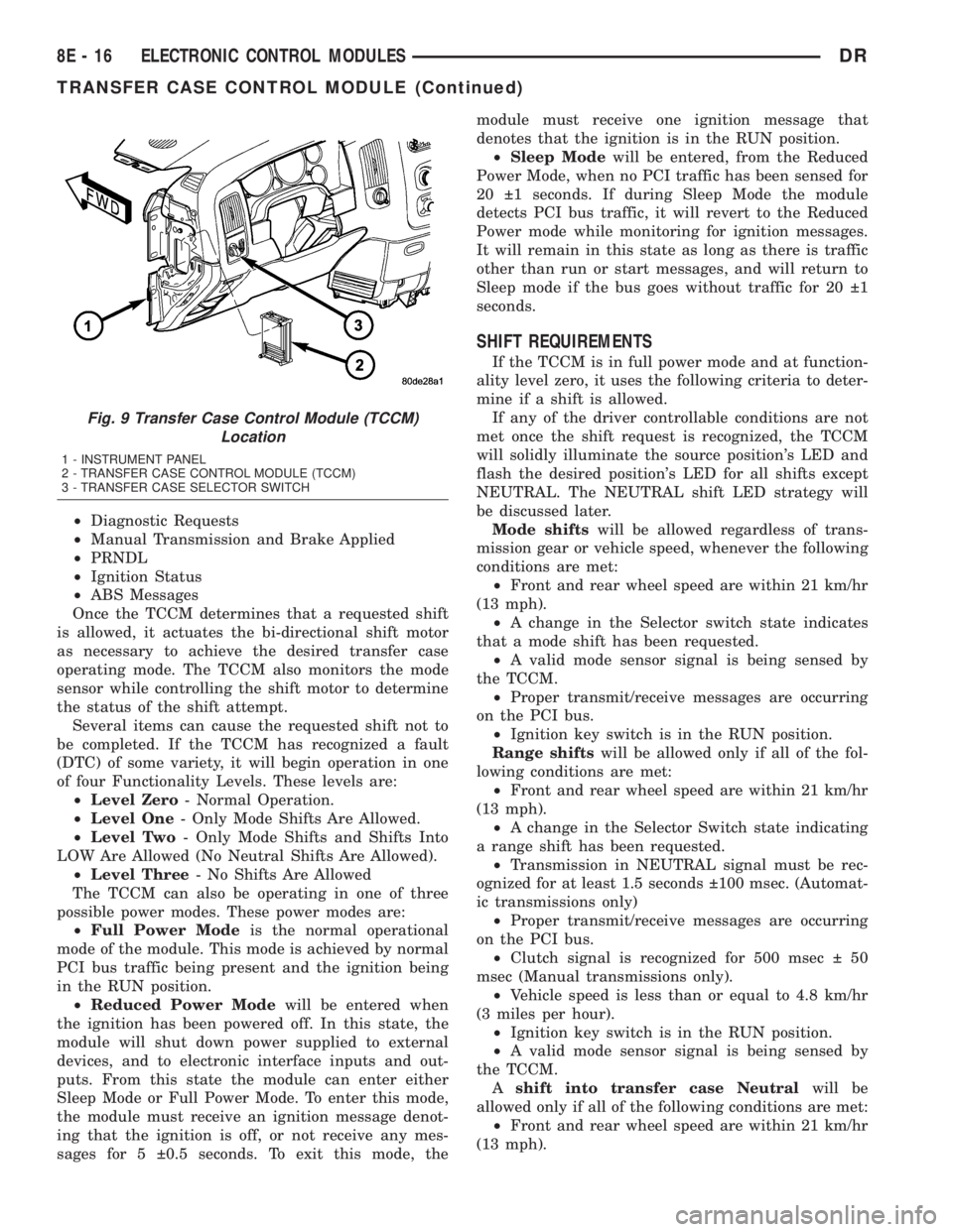
Fig. 9 Transfer Case Control Module (TCCM)
Location
1 - INSTRUMENT PANEL
2 - TRANSFER CASE CONTROL MODULE (TCCM)
3 - TRANSFER CASE SELECTOR SWITCH
8E - 16 ELECTRONIC CONTROL MODULESDR
TRANSFER CASE CONTROL MODULE (Continued)
Page 398 of 2895
²The recessed Neutral Selection switch has been
depressed continuously for 4.0 seconds 100 msec
while all shift conditions have been continuously met.
²Transmission in NEUTRAL signal recognized
from the bus. (Automatic transmissions only)
²Clutch signal is recognized from the bus (Manu-
al transmissions only).
²Proper message transmissions/receptions are
occurring on the PCI bus.
²Vehicle speed is less than or equal to 4.8 km/hr
(3 miles per hour).
²Ignition key switch is in the RUN position,
engine off.
²Foot Brake is applied.
²A valid mode sensor signal is being sensed by
the TCCM.
Ashift out of transfer case Neutralwill be
allowed only if all of the following conditions are met:
²Front and rear wheel speed are within 21 km/hr
(13 mph).
²The recessed Neutral Selection switch has been
depressed continuously for 1.0 seconds 100 msec
while all shift conditions have been continuously met.
²Transmission in NEUTRAL signal recognized
from the bus.(Automatic transmissions only)
²Clutch signal is recognized from the bus (Manu-
al transmissions only).
²Proper message transmissions/receptions are
occurring on the PCI bus.
²Vehicle speed is less than or equal to 4.8 km/hr
(3 miles per hour).
²Ignition key switch is in the RUN position.
²Foot Brake is applied.
²A valid mode sensor signal is being sensed by
the TCCM.
SHIFT SEQUENCES
Once all the driver controllable conditions for the
requested shift have been met, the TCCM begins a
shift timer with a maximum duration of 1 second per
'D' channel transition. If the shift timer expires
before the TCCM recognizes to correct mode sensor
code, the shift is considered to have been blocked.
The blocked shift will increment the blocked shift
counter by one. The TCCM strategy for handling
blocked shifts will be described later. The process the
TCCM performs for the various shifts will be
described first.
RANGE AND MODE SHIFTS
The process for performing all the range and mode
shifts are the same. The following steps describe the
process.
²Allow time for Selector Switch debounce; 250
msec 50 msec.²Extinguish the source gear's LED while flashing
desired transfer case position's LED.
²Engage the shift motor for a maximum of 1 sec-
ond 100 msec per 'D' channel transition in the des-
tination gear's direction while monitoring the mode
sensor channel transitions.
²Disengage the shift motor when the correct
mode sensor code is recognized.
²Solidly illuminate the selected gear's LED.
²Transmit a bus message that the transfer case
shift is complete.
²If the desired mode sensor code is not received
after the shift timer expires (ie. a blocked or other
condition exists), stop driving the motor and wait for
200 msec 50 msec. The shift motor is then reversed
in the direction back toward the source gear for up to
1.0 seconds 100 msec. per 'D' channel. The TCCM
waits for 2.0 seconds 50 msec. and repeats the
attempt to shift to the desired position.
The exception to the preceding sequence is when a
shift from 4L to 2WD/AWD is requested. If 2WD/
AWD is requested from the 4L position, the transfer
case is first driven to the 4H position. If the 4H posi-
tion is reached, the transfer case is then driven back
to the 2WD/AWD position and the shift is considered
complete. If the transfer case does not reach any the
4H position, but is in the 2WD/AWD 'D' channel, or
the 2WD/AWD between gear position on the 4H side
of 2WD/AWD, the shift is also considered complete.
SHIFT OUT OF NEUTRAL
²Extinguish the Neutral LED.
²Engage the shift motor for a maximum of 1 sec-
ond 100 msec toward the transfer case 4H mode
position while monitoring the mode sensor channel
transitions.
²Disengage the shift motor when the correct
mode sensor code is recognized.
²Extinguish the Neutral LED.
²Transmit a bus message that the transfer case
shift is complete.
²If the desired mode sensor code is not received
after the shift timer expires (ie. a blocked or other
condition exists), stop driving the motor and wait for
200 msec 50 msec. The shift motor is then reversed
in the direction back toward the source gear for up to
1.0 seconds 100 msec. The TCCM waits for 2.0 sec-
onds 50 msec. and repeats the attempt to shift to
the desired position.
²When the Neutral button is released, if the 4H
position is the desired position, the shift is complete.
Illuminate the 4H LED.
²Otherwise when the Neutral button is released,
if all of the shift requirements are being met then
engage the shift motor towards the desired position
for 1 second 100 msec per 'D' channel. (if require-
DRELECTRONIC CONTROL MODULES 8E - 17
TRANSFER CASE CONTROL MODULE (Continued)
Page 422 of 2895
INSTALLATION
(1) Position the battery cable in the engine com-
partment.
(2) One at a time, install the battery cable retain-
ing pushpins, fasteners and routing clips until the
cable is installed exactly where it was in the vehicle.
Refer to Wiring for illustrations.
(3) Install the battery in the vehicle. Refer to the
procedure in this group.
(4) Connect the battery negative cable terminal.
BATTERY TRAY
DESCRIPTION
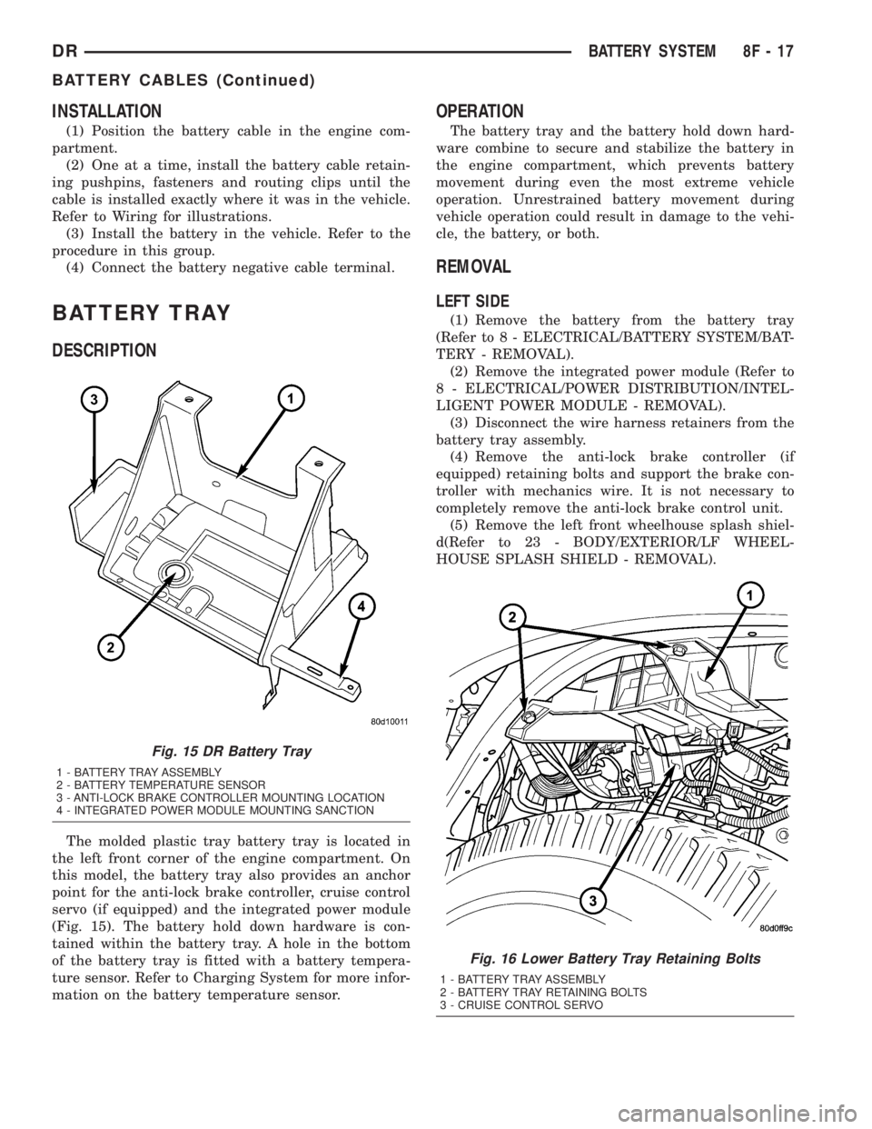
The molded plastic tray battery tray is located in
the left front corner of the engine compartment. On
this model, the battery tray also provides an anchor
point for the anti-lock brake controller, cruise control
servo (if equipped) and the integrated power module
(Fig. 15). The battery hold down hardware is con-
tained within the battery tray. A hole in the bottom
of the battery tray is fitted with a battery tempera-
ture sensor. Refer to Charging System for more infor-
mation on the battery temperature sensor.
OPERATION
The battery tray and the battery hold down hard-
ware combine to secure and stabilize the battery in
the engine compartment, which prevents battery
movement during even the most extreme vehicle
operation. Unrestrained battery movement during
vehicle operation could result in damage to the vehi-
cle, the battery, or both.
REMOVAL
LEFT SIDE
(1) Remove the battery from the battery tray
(Refer to 8 - ELECTRICAL/BATTERY SYSTEM/BAT-
TERY - REMOVAL).
(2) Remove the integrated power module (Refer to
8 - ELECTRICAL/POWER DISTRIBUTION/INTEL-
LIGENT POWER MODULE - REMOVAL).
(3) Disconnect the wire harness retainers from the
battery tray assembly.
(4) Remove the anti-lock brake controller (if
equipped) retaining bolts and support the brake con-
troller with mechanics wire. It is not necessary to
completely remove the anti-lock brake control unit.
(5) Remove the left front wheelhouse splash shiel-
d(Refer to 23 - BODY/EXTERIOR/LF WHEEL-
HOUSE SPLASH SHIELD - REMOVAL).
Fig. 15 DR Battery Tray
1 - BATTERY TRAY ASSEMBLY
2 - BATTERY TEMPERATURE SENSOR
3 - ANTI-LOCK BRAKE CONTROLLER MOUNTING LOCATION
4 - INTEGRATED POWER MODULE MOUNTING SANCTION
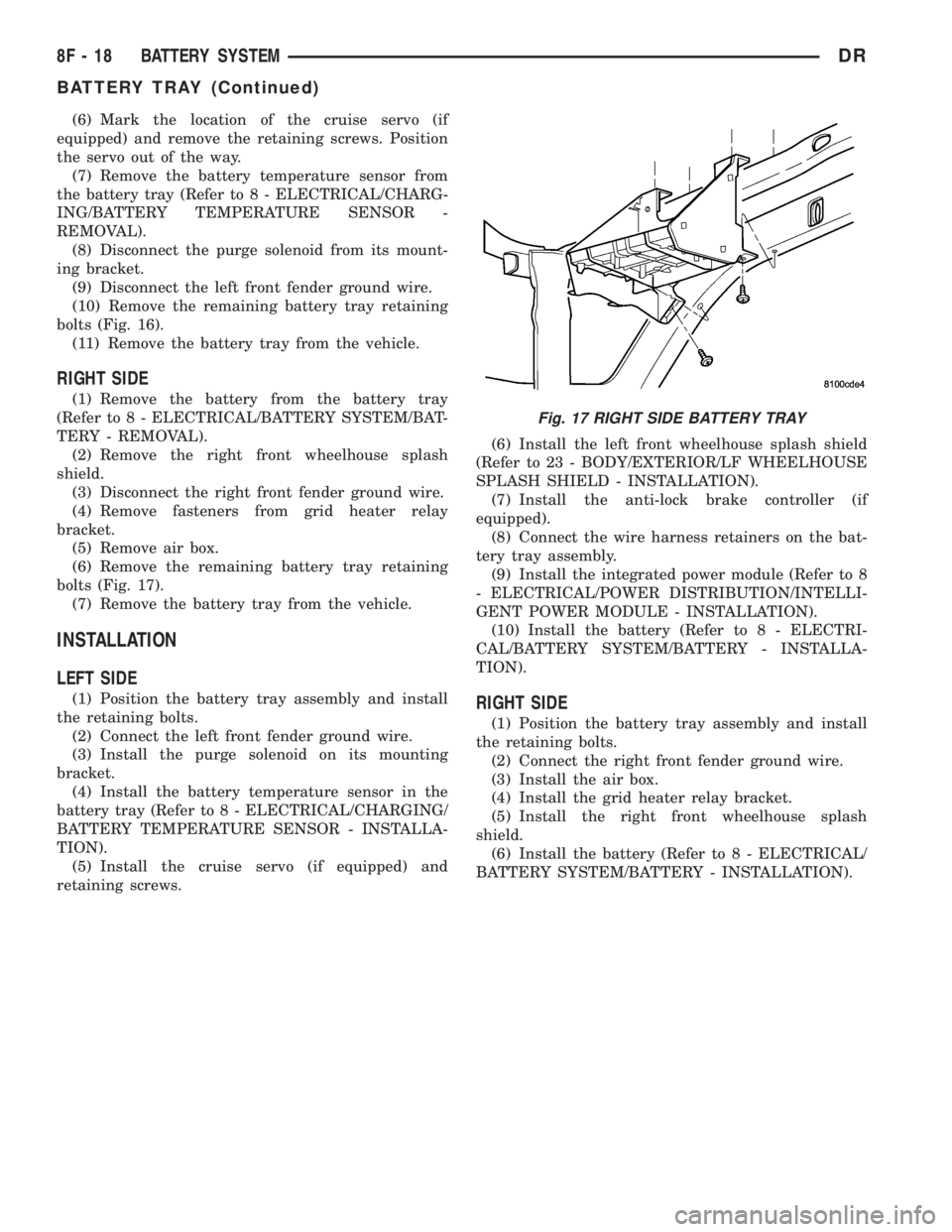
Fig. 16 Lower Battery Tray Retaining Bolts
1 - BATTERY TRAY ASSEMBLY
2 - BATTERY TRAY RETAINING BOLTS
3 - CRUISE CONTROL SERVO
DRBATTERY SYSTEM 8F - 17
BATTERY CABLES (Continued)
Page 423 of 2895
(6) Mark the location of the cruise servo (if
equipped) and remove the retaining screws. Position
the servo out of the way.
(7) Remove the battery temperature sensor from
the battery tray (Refer to 8 - ELECTRICAL/CHARG-
ING/BATTERY TEMPERATURE SENSOR -
REMOVAL).
(8) Disconnect the purge solenoid from its mount-
ing bracket.
(9) Disconnect the left front fender ground wire.
(10) Remove the remaining battery tray retaining
bolts (Fig. 16).
(11) Remove the battery tray from the vehicle.
RIGHT SIDE
(1) Remove the battery from the battery tray
(Refer to 8 - ELECTRICAL/BATTERY SYSTEM/BAT-
TERY - REMOVAL).
(2) Remove the right front wheelhouse splash
shield.
(3) Disconnect the right front fender ground wire.
(4) Remove fasteners from grid heater relay
bracket.
(5) Remove air box.
(6) Remove the remaining battery tray retaining
bolts (Fig. 17).
(7) Remove the battery tray from the vehicle.
INSTALLATION
LEFT SIDE
(1) Position the battery tray assembly and install
the retaining bolts.
(2) Connect the left front fender ground wire.
(3) Install the purge solenoid on its mounting
bracket.
(4) Install the battery temperature sensor in the
battery tray (Refer to 8 - ELECTRICAL/CHARGING/
BATTERY TEMPERATURE SENSOR - INSTALLA-
TION).
(5) Install the cruise servo (if equipped) and
retaining screws.(6) Install the left front wheelhouse splash shield
(Refer to 23 - BODY/EXTERIOR/LF WHEELHOUSE
SPLASH SHIELD - INSTALLATION).
(7) Install the anti-lock brake controller (if
equipped).
(8) Connect the wire harness retainers on the bat-
tery tray assembly.
(9) Install the integrated power module (Refer to 8
- ELECTRICAL/POWER DISTRIBUTION/INTELLI-
GENT POWER MODULE - INSTALLATION).
(10) Install the battery (Refer to 8 - ELECTRI-
CAL/BATTERY SYSTEM/BATTERY - INSTALLA-
TION).RIGHT SIDE
(1) Position the battery tray assembly and install
the retaining bolts.
(2) Connect the right front fender ground wire.
(3) Install the air box.
(4) Install the grid heater relay bracket.
(5) Install the right front wheelhouse splash
shield.
(6) Install the battery (Refer to 8 - ELECTRICAL/
BATTERY SYSTEM/BATTERY - INSTALLATION).
Fig. 17 RIGHT SIDE BATTERY TRAY
8F - 18 BATTERY SYSTEMDR
BATTERY TRAY (Continued)