headlamp DODGE RAM 2003 Service Manual PDF
[x] Cancel search | Manufacturer: DODGE, Model Year: 2003, Model line: RAM, Model: DODGE RAM 2003Pages: 2895, PDF Size: 83.15 MB
Page 1186 of 2895
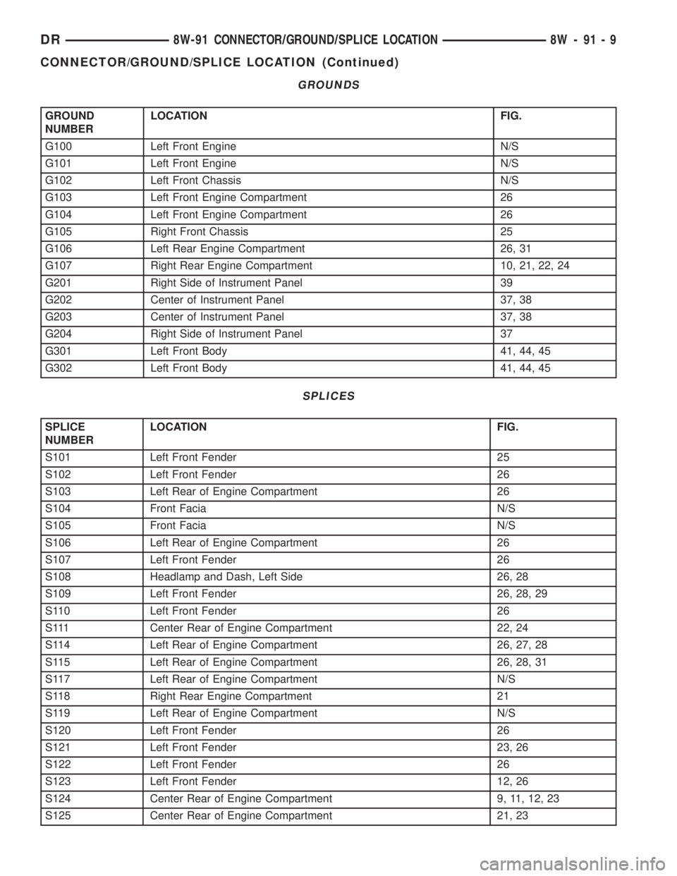
GROUNDS
GROUND
NUMBERLOCATION FIG.
G100 Left Front Engine N/S
G101 Left Front Engine N/S
G102 Left Front Chassis N/S
G103 Left Front Engine Compartment 26
G104 Left Front Engine Compartment 26
G105 Right Front Chassis 25
G106 Left Rear Engine Compartment 26, 31
G107 Right Rear Engine Compartment 10, 21, 22, 24
G201 Right Side of Instrument Panel 39
G202 Center of Instrument Panel 37, 38
G203 Center of Instrument Panel 37, 38
G204 Right Side of Instrument Panel 37
G301 Left Front Body 41, 44, 45
G302 Left Front Body 41, 44, 45
SPLICES
SPLICE
NUMBERLOCATION FIG.
S101 Left Front Fender 25
S102 Left Front Fender 26
S103 Left Rear of Engine Compartment 26
S104 Front Facia N/S
S105 Front Facia N/S
S106 Left Rear of Engine Compartment 26
S107 Left Front Fender 26
S108 Headlamp and Dash, Left Side 26, 28
S109 Left Front Fender 26, 28, 29
S110 Left Front Fender 26
S111 Center Rear of Engine Compartment 22, 24
S114 Left Rear of Engine Compartment 26, 27, 28
S115 Left Rear of Engine Compartment 26, 28, 31
S117 Left Rear of Engine Compartment N/S
S118 Right Rear Engine Compartment 21
S119 Left Rear of Engine Compartment N/S
S120 Left Front Fender 26
S121 Left Front Fender 23, 26
S122 Left Front Fender 26
S123 Left Front Fender 12, 26
S124 Center Rear of Engine Compartment 9, 11, 12, 23
S125 Center Rear of Engine Compartment 21, 23
DR8W-91 CONNECTOR/GROUND/SPLICE LOCATION 8W - 91 - 9
CONNECTOR/GROUND/SPLICE LOCATION (Continued)
Page 1187 of 2895
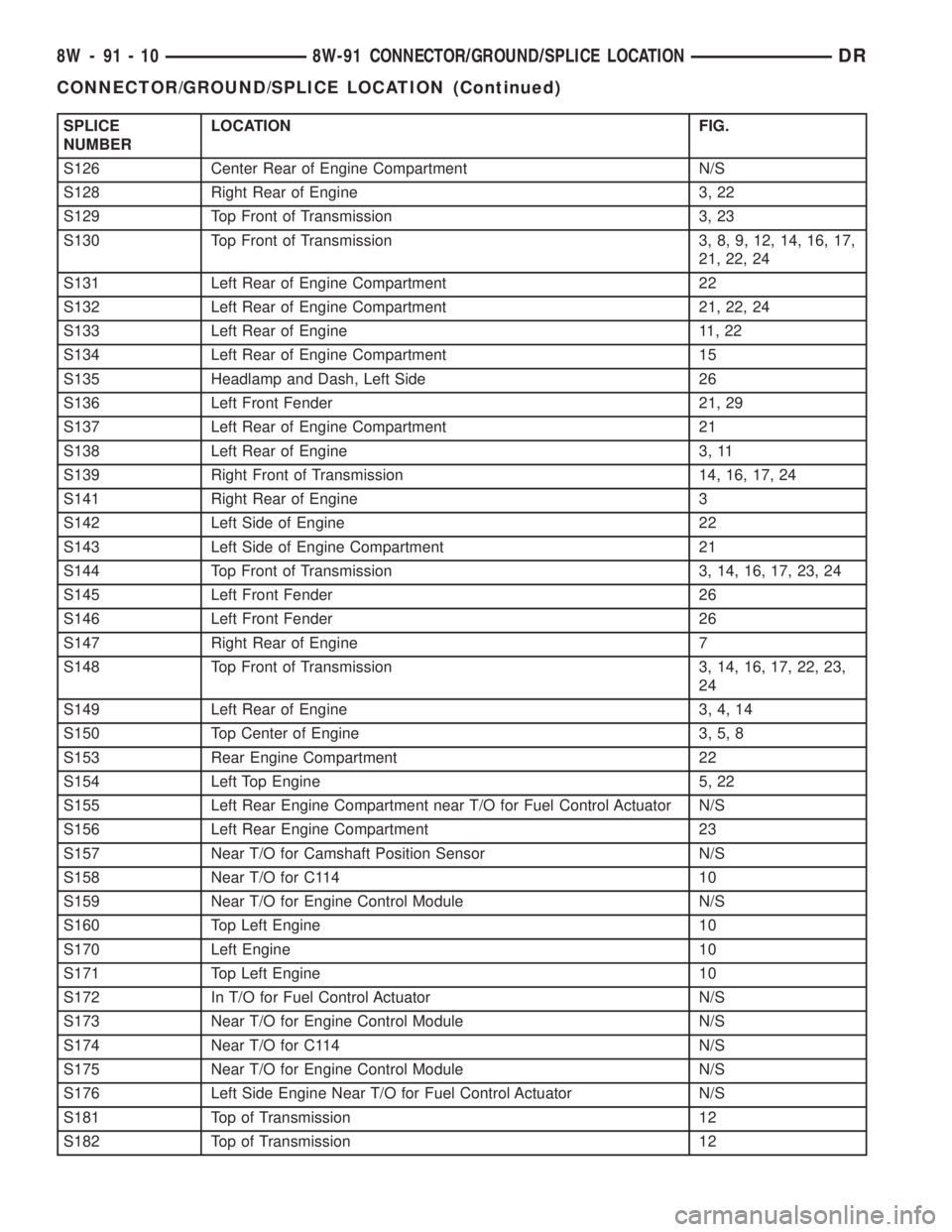
SPLICE
NUMBERLOCATION FIG.
S126 Center Rear of Engine Compartment N/S
S128 Right Rear of Engine 3, 22
S129 Top Front of Transmission 3, 23
S130 Top Front of Transmission 3, 8, 9, 12, 14, 16, 17,
21, 22, 24
S131 Left Rear of Engine Compartment 22
S132 Left Rear of Engine Compartment 21, 22, 24
S133 Left Rear of Engine 11, 22
S134 Left Rear of Engine Compartment 15
S135 Headlamp and Dash, Left Side 26
S136 Left Front Fender 21, 29
S137 Left Rear of Engine Compartment 21
S138 Left Rear of Engine 3, 11
S139 Right Front of Transmission 14, 16, 17, 24
S141 Right Rear of Engine 3
S142 Left Side of Engine 22
S143 Left Side of Engine Compartment 21
S144 Top Front of Transmission 3, 14, 16, 17, 23, 24
S145 Left Front Fender 26
S146 Left Front Fender 26
S147 Right Rear of Engine 7
S148 Top Front of Transmission 3, 14, 16, 17, 22, 23,
24
S149 Left Rear of Engine 3, 4, 14
S150 Top Center of Engine 3, 5, 8
S153 Rear Engine Compartment 22
S154 Left Top Engine 5, 22
S155 Left Rear Engine Compartment near T/O for Fuel Control Actuator N/S
S156 Left Rear Engine Compartment 23
S157 Near T/O for Camshaft Position Sensor N/S
S158 Near T/O for C114 10
S159 Near T/O for Engine Control Module N/S
S160 Top Left Engine 10
S170 Left Engine 10
S171 Top Left Engine 10
S172 In T/O for Fuel Control Actuator N/S
S173 Near T/O for Engine Control Module N/S
S174 Near T/O for C114 N/S
S175 Near T/O for Engine Control Module N/S
S176 Left Side Engine Near T/O for Fuel Control Actuator N/S
S181 Top of Transmission 12
S182 Top of Transmission 12
8W - 91 - 10 8W-91 CONNECTOR/GROUND/SPLICE LOCATIONDR
CONNECTOR/GROUND/SPLICE LOCATION (Continued)
Page 1244 of 2895
tery and provides the primary means of circuit pro-
tection and power distribution for all vehicle
electrical systems. The front control module controls
power to some of these vehicle systems electrical and
electromechanical loads based on inputs received
from hard wired switch inputs and data received on
the PCI bus circuit (J1850).
For information on theIntegrated Power Mod-
ule Refer to the Power Distribution Sectionof
the service manual.
OPERATION
As messages are sent over the PCI bus circuit, the
front control module reads these messages and con-
trols power to some of the vehicles electrical systems
by completing the circuit to ground (low side driver)
or completing the circuit to 12 volt power (high side
driver). The following functions areControlledby
the Front Control Module:
²Headlamp Power with Voltage Regulation
²Windshield Wiper ªON/OFFº Relay Actuation
²Windshield Wiper ªHI/LOº Relay Actuation
²Windshield Washer Pump Motor
²Fog Lamp Relay Actuation
²Park Lamp Relay Actuation
²Horn Relay Actuation
The following inputs areReceived/Monitoredby
the Front Control Module:
²B+ Connection Detection²Power Ground
²Ambient Temperature Sensing
²Ignition Switch Run
²Washer Fluid Level Switch
²Windshield Wiper Park Switch
²PCI Bus Circuit
DIAGNOSIS AND TESTING - FRONT CONTROL
MODULE
The front control module is a printed circuit board
based module with a on-board micro-processor. The
front control module interfaces with other electronic
modules in the vehicle via the Programmable Com-
munications Interface (PCI) data bus (J1850). In
order to obtain conclusive testing the Programmable
Communications Interface (PCI) data bus network
and all of the electronic modules that provide inputs
to, or receive outputs from the front control module
must be checked. All PCI (J1850) communication
faults must be resolved prior to further diagnosing
any front control module related issues.
The front control module was designed to be diag-
nosed with an appropriate diagnostic scan tool, such
as the DRB IIIt. The most reliable, efficient, and
accurate means to diagnose the front control module
requires the use of a DRB IIItscan tool and the
proper Body Diagnostic Procedures manual.
Before any testing of the front control module is
attempted, the battery should be fully charged and
all wire harness and ground connections inspected
around the affected areas on the vehicle.
REMOVAL
(1) Disconnect the positive and negative battery
cables from the battery.
(2) Partially remove the integrated power module
from the engine compartment (Refer to 8 - ELECTRI-
CAL/POWER DISTRIBUTION/INTEGRATED
POWER MODULE - REMOVAL).
(3)
Remove the front control module retaining
screws.
(4) Using both hands, pull the front control module
straightfrom the integrated power module assembly
to disconnect the 49-way electrical connector and
remove the front control module from the vehicle.
INSTALLATION
(1) Install the front control module on the inte-
grated power module assembly by pushing the
49-way electrical connector straight in.
(2) Install the front control module retaining
screws. Torque the screws to 7 in. lbs.
(3) Install the integrated power module (Refer to 8
- ELECTRICAL/POWER DISTRIBUTION/INTE-
GRATED POWER MODULE - INSTALLATION).
(4)
Connect the positive and negative battery cables.
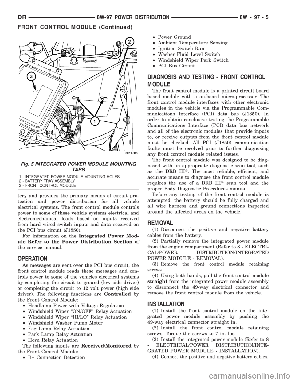
Fig. 5 INTEGRATED POWER MODULE MOUNTING
TABS
1 - INTEGRATED POWER MODULE MOUNTING HOLES
2 - BATTERY TRAY ASSEMBLY
3 - FRONT CONTROL MODULE
DR8W-97 POWER DISTRIBUTION 8W - 97 - 5
FRONT CONTROL MODULE (Continued)
Page 1683 of 2895
STANDARD PROCEDURE - HYDROFORM
FENDER RAIL REPAIR
SAFETY PRECAUTIONS AND WARNINGS
WARNING: USE EYE PROTECTION WHEN GRIND-
ING OR WELDING METAL, SERIOUS EYE INJURY
CAN RESULT.
²BEFORE PROCEEDING WITH FRAME REPAIR
INVOLVING GRINDING OR WELDING, VERIFY THAT
VEHICLE FUEL SYSTEM IS NOT LEAKING OR IN
CONTACT WITH REPAIR AREA, PERSONAL INJURY
CAN RESULT.
²DO NOT ALLOW OPEN FLAME OR HEAT AND
METAL SPATTER FROM ARC WELDING, TO CON-
TACT PLASTIC BODY PANELS. FIRE OR EXPLO-
SION CAN RESULT.
²WHEN WELDED FRAME COMPONENTS ARE
REPLACED, ENSURE COMPLETE PENETRATION
WELD IS ACHIEVED DURING INSTALLATION. IF
NOT, DANGEROUS OPERATING CONDITIONS CAN
RESULT.
²STAND CLEAR OF CABLES OR CHAINS ON
PULLING EQUIPMENT DURING FRAME STRAIGHT-
ENING OPERATIONS, PERSONAL INJURY CAN
RESULT.
²DO NOT VENTURE UNDER A HOISTED VEHI-
CLE THAT IS NOT SUPPORTED ON SAFETY
STANDS, PERSONAL INJURY CAN RESULT.
CAUTION: Do not reuse damaged fasteners, quality
of repair would be suspect. Failure to use only pro-
duction fasteners or fasteners of equivalent hard-
ness can result in loosening or failure. Do not drill
holes in top or bottom frame rail flanges, frame rail
failure can result. When using heat to straighten
frame components do not exceed 566ÉC (1050ÉF),
metal fatigue can result.
CAUTION: This repair procedure assumes damage
to the right or left hydroform fender rail (Fig. 19).
Prior to any repairs, the vehicle must be mounted
on the appropriate frame repair equipment (ªframe
rackº), checked with three dimensional measuring
equipment, and necessary pull corrections made. If
damage exists in the hydroform fender rail, or cab
beyond the area covered by this service procedure
after dimensional corrections are made, the hydro-
form must be replaced in its entirety. Refer to 23 -
BODY/BODY STRUCTURE/WELD LOCATIONS -
SPECIFICATIONS, when replacing the entire hydro-
form.(1) Disconnect and isolate the battery negative
cable.
(2) Remove the front wheelhouse splash shield.
(Refer to 23 - BODY/EXTERIOR/FRONT WHEEL-
HOUSE SPLASH SHIELD - REMOVAL)
(3) Remove the fender. (Refer to 23 - BODY/EXTE-
RIOR/FRONT FENDER - REMOVAL)
(4) Remove the A/C condenser, if required. (Refer
to 24 - HEATING & AIR CONDITIONING/PLUMB-
ING/A/C CONDENSER - REMOVAL)
(5) Remove the A/C lines, if required. Refer to the
Heating and Air Conditioning section of the manual
for recommended procedures.
(6) Remove the radiator assembly. (Refer to 7 -
COOLING/ENGINE/RADIATOR - REMOVAL)
(7) Remove the air cleaner and support bracket, if
required. (Refer to 9 - ENGINE/AIR INTAKE SYS-
TEM/AIR CLEANER ELEMENT - REMOVAL)
(8) Remove the integrated power module. (Refer to
8 - ELECTRICAL/POWER DISTRIBUTION/INTE-
GRATED POWER MODULE - REMOVAL)
(9) Remove the bolts and position aside the wire
harness and grounds, if required.
(10) Remove the upper radiator crossmember.
(Refer to 23 - BODY/EXTERIOR/UPPER RADIATOR
CROSSMEMBER - REMOVAL)
(11) Remove the headlamp unit. (Refer to 8 -
ELECTRICAL/LAMPS/LIGHTING - EXTERIOR/
HEADLAMP UNIT - REMOVAL)
(12) Remove the front cab mount to the Front End
Sheet Metal bracket (FESM) bolt.
(13) Remove the bolts attaching the lower radiator
crossmember to the hydroform fender rail. (Fig. 19)
CAUTION: Do not use any flame or plasma cutting
equipment to cut the frame in this procedure. The
inaccurate and high temperatures achieved during
flame or plasma cutting will change the metal char-
acteristics and may weaken the frame and/or repair
location.
(14) Using a reciprocating saw or equivalent, cut
the fender rail and shotgun at a straight and square
section of the hydroform and remove.
(15) Smooth and square the cut edges.
(16) Using the damaged structure as a reference
cut the service part at the same location as the first
cut. Smooth and square the cut edges.
NOTE: The repair structure should butt up to the
remaining structure and provide the same overall
vehicle geometry.
13 - 12 FRAMES & BUMPERSDR
FRAME (Continued)
Page 1685 of 2895
(26) Install the front cab mount bolt if previously
removed and tighten to 81 N´m (60 ft. lbs.).
(27) Install the lower radiator crossmember bolts
and tighten to 28 N´m (21 ft. lbs.).
(28) Install the headlamp unit. (Refer to 8 - ELEC-
TRICAL/LAMPS/LIGHTING - EXTERIOR/HEAD-
LAMP UNIT - INSTALLATION)
(29) Install the upper radiator crossmember. (Refer
to 23 - BODY/EXTERIOR/UPPER RADIATOR
CROSSMEMBER - INSTALLATION)
(30) Install the wire harness and ground if previ-
ously removed and install the bolts.
(31) Install the integrated power module, if previ-
ously removed. (Refer to 8 - ELECTRICAL/POWER
DISTRIBUTION/INTEGRATED POWER MODULE -
INSTALLATION)
(32) Install the air cleaner bracket and air cleaner,
if previously removed. (Refer to 9 - ENGINE/AIR
INTAKE SYSTEM/AIR CLEANER ELEMENT -
INSTALLATION)(33) Install the radiator assembly. (Refer to 7 -
COOLING/ENGINE/RADIATOR - INSTALLATION)
(34) Install the A/C lines, if previously removed.
Refer to the Heating and Air Conditioning section of
the manual for the recommended procedures.
(35) Install the A/C condenser, if previously
removed. (Refer to 24 - HEATING & AIR CONDI-
TIONING/PLUMBING/A/C CONDENSER - INSTAL-
LATION)
(36) Install the fender. (Refer to 23 - BODY/EXTE-
RIOR/FRONT FENDER - INSTALLATION)
(37) Install the front wheelhouse splash shield.
(Refer to 23 - BODY/EXTERIOR/FRONT WHEEL-
HOUSE SPLASH SHIELD - INSTALLATION)
(38) Reconnect the battery ground.
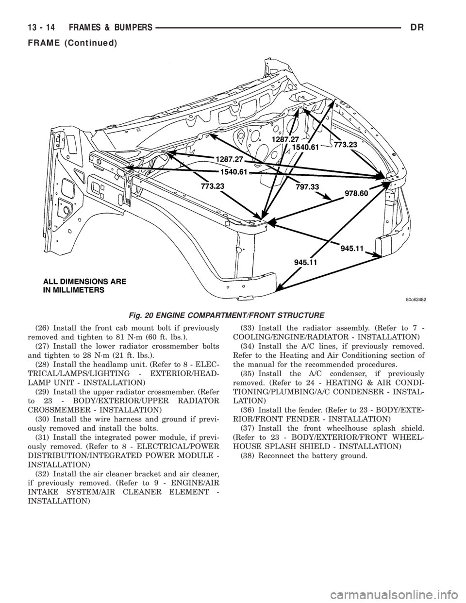
Fig. 20 ENGINE COMPARTMENT/FRONT STRUCTURE
13 - 14 FRAMES & BUMPERSDR
FRAME (Continued)
Page 2614 of 2895
FRONT FENDER
REMOVAL
(1) Remove the antenna, if equipped. (Refer to 8 -
ELECTRICAL/AUDIO/ANTENNA BODY & CABLE -
REMOVAL)
(2) Remove the battery tray, if required. (Refer to 8
- ELECTRICAL/BATTERY SYSTEM/TRAY -
REMOVAL)
(3) Remove the cowl grille. (Refer to 23 - BODY/
EXTERIOR/COWL GRILLE - REMOVAL)
(4) Remove the headlamp unit. (Refer to 8 - ELEC-
TRICAL/LAMPS/LIGHTING - EXTERIOR/HEAD-
LAMP UNIT - REMOVAL)
(5) Remove the wheelhouse splash shield. (Refer to
23 - BODY/EXTERIOR/FRONT WHEELHOUSE
SPLASH SHIELD - REMOVAL)
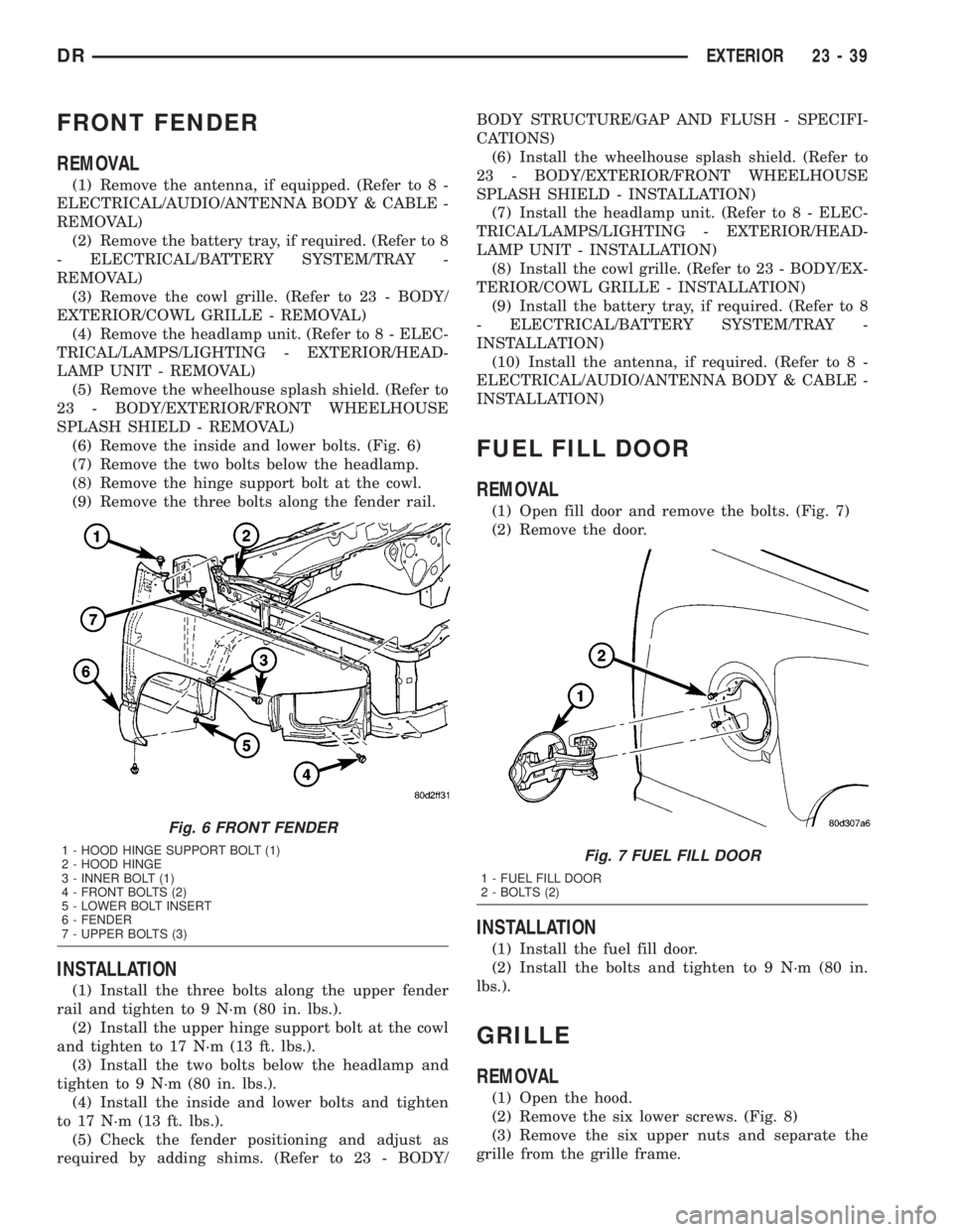
(6) Remove the inside and lower bolts. (Fig. 6)
(7) Remove the two bolts below the headlamp.
(8) Remove the hinge support bolt at the cowl.
(9) Remove the three bolts along the fender rail.
INSTALLATION
(1) Install the three bolts along the upper fender
rail and tighten to 9 N´m (80 in. lbs.).
(2) Install the upper hinge support bolt at the cowl
and tighten to 17 N´m (13 ft. lbs.).
(3) Install the two bolts below the headlamp and
tighten to 9 N´m (80 in. lbs.).
(4) Install the inside and lower bolts and tighten
to 17 N´m (13 ft. lbs.).
(5) Check the fender positioning and adjust as
required by adding shims. (Refer to 23 - BODY/BODY STRUCTURE/GAP AND FLUSH - SPECIFI-
CATIONS)
(6) Install the wheelhouse splash shield. (Refer to
23 - BODY/EXTERIOR/FRONT WHEELHOUSE
SPLASH SHIELD - INSTALLATION)
(7) Install the headlamp unit. (Refer to 8 - ELEC-
TRICAL/LAMPS/LIGHTING - EXTERIOR/HEAD-
LAMP UNIT - INSTALLATION)
(8) Install the cowl grille. (Refer to 23 - BODY/EX-
TERIOR/COWL GRILLE - INSTALLATION)
(9) Install the battery tray, if required. (Refer to 8
- ELECTRICAL/BATTERY SYSTEM/TRAY -
INSTALLATION)
(10) Install the antenna, if required. (Refer to 8 -
ELECTRICAL/AUDIO/ANTENNA BODY & CABLE -
INSTALLATION)
FUEL FILL DOOR
REMOVAL
(1) Open fill door and remove the bolts. (Fig. 7)
(2) Remove the door.
INSTALLATION
(1) Install the fuel fill door.
(2) Install the bolts and tighten to 9 N´m (80 in.
lbs.).
GRILLE
REMOVAL
(1) Open the hood.
(2) Remove the six lower screws. (Fig. 8)
(3) Remove the six upper nuts and separate the
grille from the grille frame.
Fig. 6 FRONT FENDER
1 - HOOD HINGE SUPPORT BOLT (1)
2 - HOOD HINGE
3 - INNER BOLT (1)
4 - FRONT BOLTS (2)
5 - LOWER BOLT INSERT
6 - FENDER
7 - UPPER BOLTS (3)Fig. 7 FUEL FILL DOOR
1 - FUEL FILL DOOR
2 - BOLTS (2)
DREXTERIOR 23 - 39
Page 2625 of 2895
INSTRUMENT PANEL
TABLE OF CONTENTS
page page
CLUSTER BEZEL
REMOVAL.............................50
INSTALLATION.........................50
ASH RECEIVER
REMOVAL.............................51
INSTALLATION.........................52
CUP HOLDER
REMOVAL.............................52
INSTALLATION.........................52
GLOVE BOX
REMOVAL.............................53
INSTALLATION.........................53
GLOVE BOX LATCH
REMOVAL.............................53
INSTALLATION.........................53
INSTRUMENT PANEL ASSEMBLY
REMOVAL.............................53
INSTALLATION.........................56
INSTRUMENT PANEL HEADLAMP SWITCH
BEZEL
REMOVAL.............................57
INSTALLATION.........................57INSTRUMENT PANEL CENTER BEZEL
REMOVAL.............................58
INSTALLATION.........................58
INSTRUMENT PANEL DRIVER SIDE BEZEL
REMOVAL.............................58
INSTALLATION.........................59
INSTRUMENT PANEL TOP COVER
REMOVAL.............................59
INSTALLATION.........................60
INSTRUMENT PANEL LOWER SURROUND
REMOVAL.............................60
INSTALLATION.........................60
STEERING COLUMN OPENING COVER
REMOVAL.............................61
INSTALLATION.........................61
STEERING COLUMN OPENING SUPPORT
BRACKET
REMOVAL.............................61
INSTALLATION.........................62
STORAGE BIN
REMOVAL.............................62
INSTALLATION.........................62
CLUSTER BEZEL
REMOVAL
WARNING: ON VEHICLES EQUIPPED WITH AIR-
BAGS, DISABLE THE AIRBAG SYSTEM BEFORE
ATTEMPTING ANY STEERING WHEEL, STEERING
COLUMN, SEAT BELT TENSIONER, OR INSTRU-
MENT PANEL COMPONENT DIAGNOSIS OR SER-
VICE. DISCONNECT AND ISOLATE THE BATTERY
NEGATIVE (GROUND) CABLE, THEN WAIT TWO
MINUTES FOR THE AIRBAG SYSTEM CAPACITOR
TO DISCHARGE BEFORE PERFORMING FURTHER
DIAGNOSIS OR SERVICE. THIS IS THE ONLY SURE
WAY TO DISABLE THE AIRBAG SYSTEM. FAILURE
TO TAKE THE PROPER PRECAUTIONS COULD
RESULT IN ACCIDENTAL AIRBAG DEPLOYMENT
AND POSSIBLE PERSONAL INJURY.
(1) Remove the headlamp switch bezel. (Refer to
23 - BODY/INSTRUMENT PANEL/INSTRUMENT
PANEL SWITCH BEZEL - REMOVAL)
(2) Remove the center bezel. (Refer to 23 - BODY/
INSTRUMENT PANEL/INSTRUMENT PANEL
CENTER BEZEL - REMOVAL)(3) Remove the two top screws. (Fig. 1)
(4) Using a trim stick C-4755 or equivalent, sepa-
rate the two lower clips.
(5) Disengage the two top attachment bosses and
remove the bezel.
INSTALLATION
WARNING: ON VEHICLES EQUIPPED WITH AIR-
BAGS, DISABLE THE AIRBAG SYSTEM BEFORE
ATTEMPTING ANY STEERING WHEEL, STEERING
COLUMN, SEAT BELT TENSIONER, OR INSTRU-
MENT PANEL COMPONENT DIAGNOSIS OR SER-
VICE. DISCONNECT AND ISOLATE THE BATTERY
NEGATIVE (GROUND) CABLE, THEN WAIT TWO
MINUTES FOR THE AIRBAG SYSTEM CAPACITOR
TO DISCHARGE BEFORE PERFORMING FURTHER
DIAGNOSIS OR SERVICE. THIS IS THE ONLY SURE
WAY TO DISABLE THE AIRBAG SYSTEM. FAILURE
TO TAKE THE PROPER PRECAUTIONS COULD
RESULT IN ACCIDENTAL AIRBAG DEPLOYMENT
AND POSSIBLE PERSONAL INJURY.
(1) Position the cluster bezel over the cluster and
seat the outer bosses over the posts on the left and
right sides.
23 - 50 INSTRUMENT PANELDR
Page 2626 of 2895
(2) Snap the top edge of the bezel into place fully.
(3) Seat the two bottom clips fully.
(4) Install the two top screws.
(5) Install the center bezel (Refer to 23 - BODY/
INSTRUMENT PANEL/INSTRUMENT PANEL
CENTER BEZEL - INSTALLATION)
(6) Install the headlamp switch bezel. (Refer to 23
- BODY/INSTRUMENT PANEL/INSTRUMENT
PANEL SWITCH BEZEL - INSTALLATION)
ASH RECEIVER
REMOVAL
WARNING: ON VEHICLES EQUIPPED WITH AIR-
BAGS, DISABLE THE AIRBAG SYSTEM BEFORE
ATTEMPTING ANY STEERING WHEEL, STEERING
COLUMN, SEAT BELT TENSIONER, OR INSTRU-
MENT PANEL COMPONENT DIAGNOSIS OR SER-
VICE. DISCONNECT AND ISOLATE THE BATTERY
NEGATIVE (GROUND) CABLE, THEN WAIT TWO
MINUTES FOR THE AIRBAG SYSTEM CAPACITOR
TO DISCHARGE BEFORE PERFORMING FURTHER
DIAGNOSIS OR SERVICE. THIS IS THE ONLY SURE
WAY TO DISABLE THE AIRBAG SYSTEM. FAILURE
TO TAKE THE PROPER PRECAUTIONS COULD
RESULT IN ACCIDENTAL AIRBAG DEPLOYMENT
AND POSSIBLE PERSONAL INJURY.(1) Open ash receiver and place hand inside. (Fig.
2)
(2) Apply force with anabruptdownward motion
and roll rearward. (Fig. 3)
(3) Dislodge and roll ash receiver out of panel to
remove.
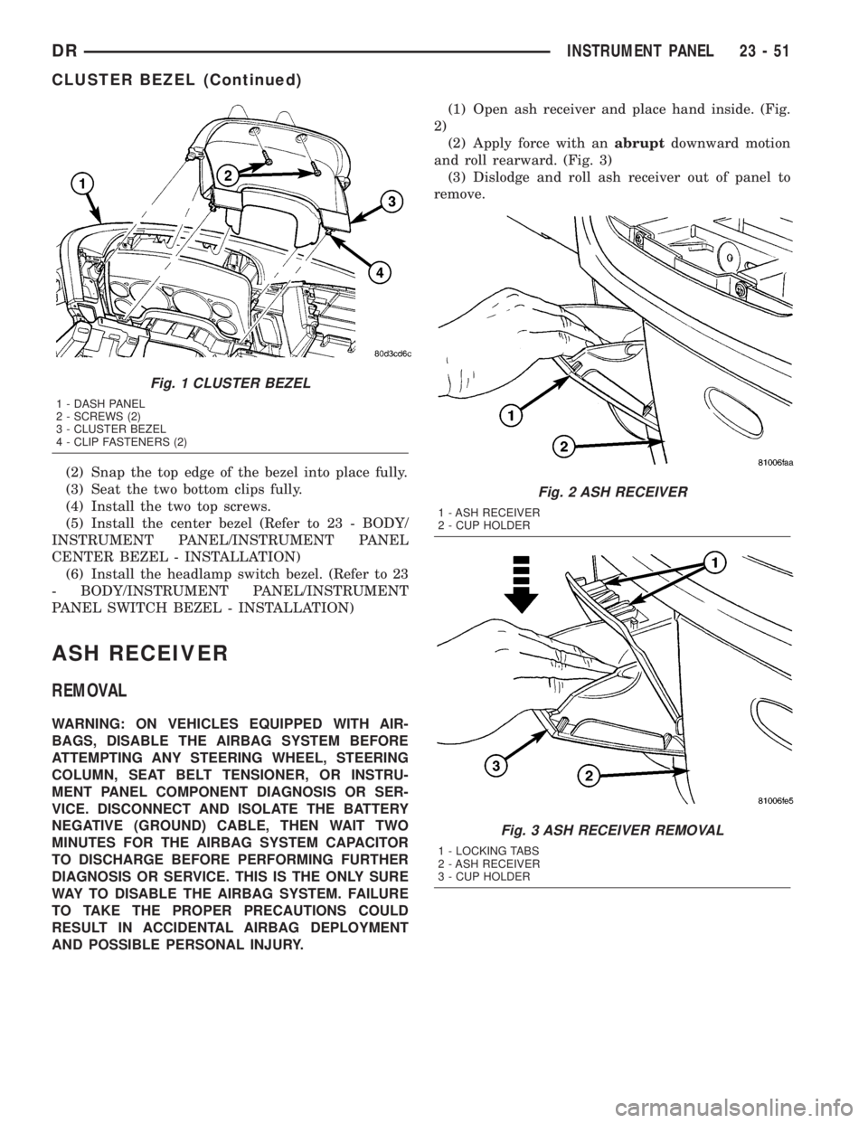
Fig. 1 CLUSTER BEZEL
1 - DASH PANEL
2 - SCREWS (2)
3 - CLUSTER BEZEL
4 - CLIP FASTENERS (2)
Fig. 2 ASH RECEIVER
1 - ASH RECEIVER
2 - CUP HOLDER
Fig. 3 ASH RECEIVER REMOVAL
1 - LOCKING TABS
2 - ASH RECEIVER
3 - CUP HOLDER
DRINSTRUMENT PANEL 23 - 51
CLUSTER BEZEL (Continued)
Page 2632 of 2895
(11) Install the right a-pillar trim panel. (Refer to
23 - BODY/INTERIOR/A-PILLAR TRIM - INSTAL-
LATION)
(12) Position the right end cap and seat the
attachment clips fully.
(13) Install the one HVAC mounting screw.
(14) Connect the radio antenna.
(15) Connect the two electrical connectors at the
right cowl panel.
(16) Install the right cowl trim cover. (Refer to 23 -
BODY/INTERIOR/COWL TRIM - INSTALLATION)
(17) Connect the air bag control module electrical
connector.
(18) Install the center bracket bolts and tighten to
12 N´m (9 ft. lbs.).
(19) Install the floor console, if equipped. (Refer to
23 - BODY/INTERIOR/FLOOR CONSOLE - INSTAL-
LATION)
(20) Install the air bag control module cover, if
equipped.
(21) Connect the park brake release handle actua-
tor rod.
(22) Install the hood release handle and tighten
the screws.
(23) Install the two bolts at the column support
bracket and tighten to 14 N´m (10 ft. lbs.).
(24) Install the steering column. (Refer to 19 -
STEERING/COLUMN - INSTALLATION)
(25) Connect the wire harness electrical connectors
above the brake pedal.
(26) Install the two top instrument panel bolts and
tighten to 12 N´m (9 ft. lbs.).
(27) Install the four top instrument panel screws.
(28) Install the instrument panel top cover. (Refer
to 23 - BODY/INSTRUMENT PANEL/INSTRUMENT
PANEL TOP COVER - INSTALLATION)
INSTRUMENT PANEL
HEADLAMP SWITCH BEZEL
REMOVAL
WARNING: ON VEHICLES EQUIPPED WITH AIR-
BAGS, DISABLE THE AIRBAG SYSTEM BEFORE
ATTEMPTING ANY STEERING WHEEL, STEERING
COLUMN, SEAT BELT TENSIONER, OR INSTRU-
MENT PANEL COMPONENT DIAGNOSIS OR SER-
VICE. DISCONNECT AND ISOLATE THE BATTERY
NEGATIVE (GROUND) CABLE, THEN WAIT TWO
MINUTES FOR THE AIRBAG SYSTEM CAPACITOR
TO DISCHARGE BEFORE PERFORMING FURTHER
DIAGNOSIS OR SERVICE. THIS IS THE ONLY SURE
WAY TO DISABLE THE AIRBAG SYSTEM. FAILURE
TO TAKE THE PROPER PRECAUTIONS COULDRESULT IN ACCIDENTAL AIRBAG DEPLOYMENT
AND POSSIBLE PERSONAL INJURY.
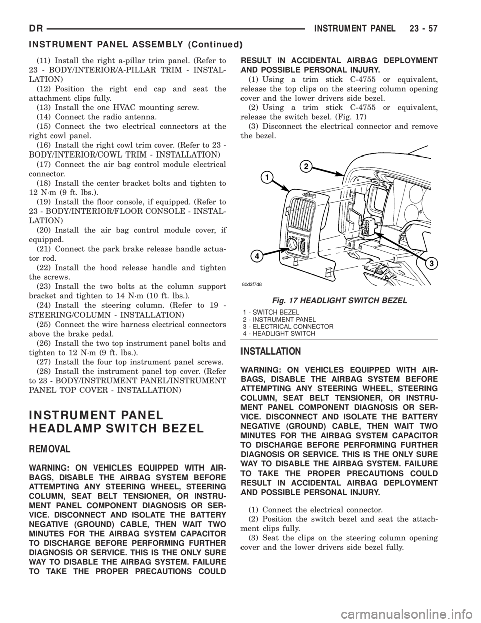
(1) Using a trim stick C-4755 or equivalent,
release the top clips on the steering column opening
cover and the lower drivers side bezel.
(2) Using a trim stick C-4755 or equivalent,
release the switch bezel. (Fig. 17)
(3) Disconnect the electrical connector and remove
the bezel.
INSTALLATION
WARNING: ON VEHICLES EQUIPPED WITH AIR-
BAGS, DISABLE THE AIRBAG SYSTEM BEFORE
ATTEMPTING ANY STEERING WHEEL, STEERING
COLUMN, SEAT BELT TENSIONER, OR INSTRU-
MENT PANEL COMPONENT DIAGNOSIS OR SER-
VICE. DISCONNECT AND ISOLATE THE BATTERY
NEGATIVE (GROUND) CABLE, THEN WAIT TWO
MINUTES FOR THE AIRBAG SYSTEM CAPACITOR
TO DISCHARGE BEFORE PERFORMING FURTHER
DIAGNOSIS OR SERVICE. THIS IS THE ONLY SURE
WAY TO DISABLE THE AIRBAG SYSTEM. FAILURE
TO TAKE THE PROPER PRECAUTIONS COULD
RESULT IN ACCIDENTAL AIRBAG DEPLOYMENT
AND POSSIBLE PERSONAL INJURY.
(1) Connect the electrical connector.
(2) Position the switch bezel and seat the attach-
ment clips fully.
(3) Seat the clips on the steering column opening
cover and the lower drivers side bezel fully.
Fig. 17 HEADLIGHT SWITCH BEZEL
1 - SWITCH BEZEL
2 - INSTRUMENT PANEL
3 - ELECTRICAL CONNECTOR
4 - HEADLIGHT SWITCH
DRINSTRUMENT PANEL 23 - 57
INSTRUMENT PANEL ASSEMBLY (Continued)
Page 2671 of 2895
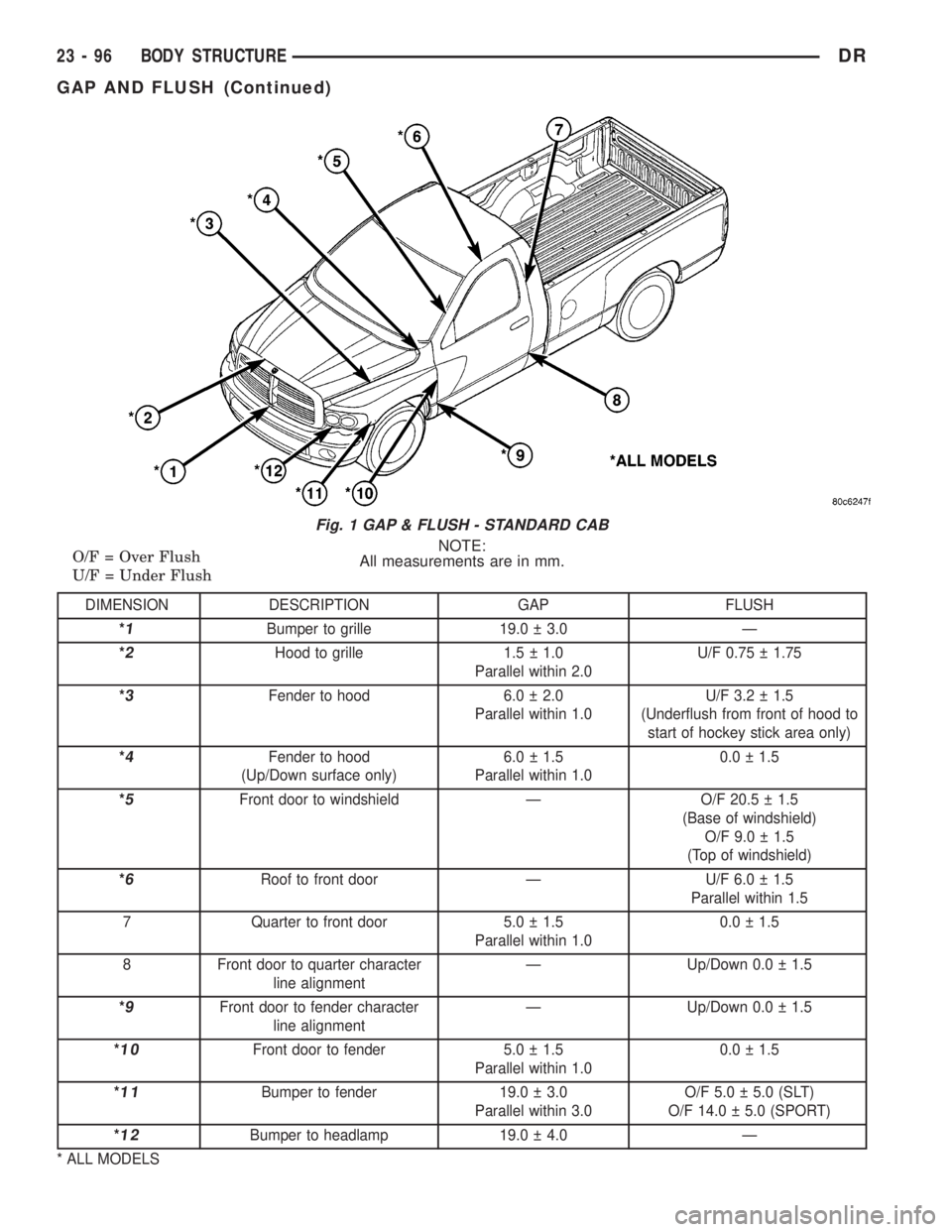
NOTE:
All measurements are in mm. O/F = Over Flush
U/F = Under Flush
DIMENSION DESCRIPTION GAP FLUSH
*
1Bumper to grille 19.0 3.0 Ð
*
2Hood to grille 1.5 1.0
Parallel within 2.0U/F 0.75 1.75
*
3Fender to hood 6.0 2.0
Parallel within 1.0U/F 3.2 1.5
(Underflush from front of hood to
start of hockey stick area only)
*
4Fender to hood
(Up/Down surface only)6.0 1.5
Parallel within 1.00.0 1.5
*
5Front door to windshield Ð O/F 20.5 1.5
(Base of windshield)
O/F 9.0 1.5
(Top of windshield)
*
6Roof to front door Ð U/F 6.0 1.5
Parallel within 1.5
7 Quarter to front door 5.0 1.5
Parallel within 1.00.0 1.5
8 Front door to quarter character
line alignmentÐ Up/Down 0.0 1.5
*
9Front door to fender character
line alignmentÐ Up/Down 0.0 1.5
*
10Front door to fender 5.0 1.5
Parallel within 1.00.0 1.5
*
11Bumper to fender 19.0 3.0
Parallel within 3.0O/F 5.0 5.0 (SLT)
O/F 14.0 5.0 (SPORT)
*
12Bumper to headlamp 19.0 4.0 Ð
* ALL MODELS
Fig. 1 GAP & FLUSH - STANDARD CAB
23 - 96 BODY STRUCTUREDR
GAP AND FLUSH (Continued)