brake light DODGE RAM 2003 Service Repair Manual
[x] Cancel search | Manufacturer: DODGE, Model Year: 2003, Model line: RAM, Model: DODGE RAM 2003Pages: 2895, PDF Size: 83.15 MB
Page 7 of 2895
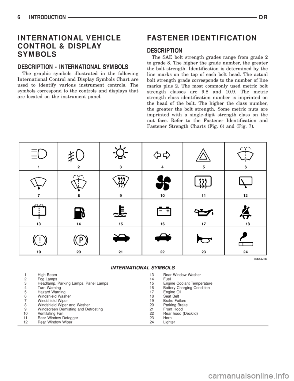
INTERNATIONAL VEHICLE
CONTROL & DISPLAY
SYMBOLS
DESCRIPTION - INTERNATIONAL SYMBOLS
The graphic symbols illustrated in the following
International Control and Display Symbols Chart are
used to identify various instrument controls. The
symbols correspond to the controls and displays that
are located on the instrument panel.
FASTENER IDENTIFICATION
DESCRIPTION
The SAE bolt strength grades range from grade 2
to grade 8. The higher the grade number, the greater
the bolt strength. Identification is determined by the
line marks on the top of each bolt head. The actual
bolt strength grade corresponds to the number of line
marks plus 2. The most commonly used metric bolt
strength classes are 9.8 and 10.9. The metric
strength class identification number is imprinted on
the head of the bolt. The higher the class number,
the greater the bolt strength. Some metric nuts are
imprinted with a single-digit strength class on the
nut face. Refer to the Fastener Identification and
Fastener Strength Charts (Fig. 6) and (Fig. 7).
INTERNATIONAL SYMBOLS
1 High Beam 13 Rear Window Washer
2 Fog Lamps 14 Fuel
3 Headlamp, Parking Lamps, Panel Lamps 15 Engine Coolant Temperature
4 Turn Warning 16 Battery Charging Condition
5 Hazard Warning 17 Engine Oil
6 Windshield Washer 18 Seat Belt
7 Windshield Wiper 19 Brake Failure
8 Windshield Wiper and Washer 20 Parking Brake
9 Windscreen Demisting and Defrosting 21 Front Hood
10 Ventilating Fan 22 Rear hood (Decklid)
11 Rear Window Defogger 23 Horn
12 Rear Window Wiper 24 Lighter
6 INTRODUCTIONDR
Page 19 of 2895
MAINTENANCE SCHEDULES
DESCRIPTION
Maintenance Schedule Information not included in
this section, is located in the appropriate Owner's
Manual.
There are two maintenance schedules that show
therequiredservice for your vehicle.
First is ScheduleªBº. It is for vehicles that are
operated under the conditions that are listed below
and at the beginning of the schedule.
²Day or night temperatures are below 0É C (32É
F).
²Stop and go driving.
²Extensive engine idling.
²Driving in dusty conditions.
²Short trips of less than 16 km (10 miles).
²More than 50% of your driving is at sustained
high speeds during hot weather, above 32É C (90É F).
²Trailer towing.
²Taxi, police, or delivery service (commercial ser-
vice).
²Off-road or desert operation.
²If equipped for and operating with E-85
(ethanol) fuel.
NOTE: Most vehicles are operated under the condi-
tions listed for Schedule(B(.
Second is ScheduleªAº. It is for vehicles that are
not operated under any of the conditions listed under
Schedule9B9.
Use the schedule that best describes your driving
conditions. Where time and mileage are listed, follow
the interval that occurs first.
CAUTION: Failure to perform the required mainte-
nance items may result in damage to the vehicle.
At Each Stop for Fuel
²Check the engine oil level about 5 minutes after
a fully warmed engine is shut off. Checking the oil
level while the vehicle is on level ground will
improve the accuracy of the oil level reading. Add oil
only when the level is at or below the ADD or MIN
mark.
²Check the windshield washer solvent and add if
required.
Once a Month
²Check tire pressure and look for unusual wear
or damage.
²Inspect the battery and clean and tighten the
terminals as required.
²Check the fluid levels of coolant reservoir, brake
master cylinder, power steering and transmission
and add as needed.
²Check all lights and all other electrical items for
correct operation.
At Each Oil Change
²Change the engine oil filter.
²Inspect the exhaust system.
²Inspect the brake hoses.
²Inspect the CV joints (if equipped) and front sus-
pension components.
²Check the automatic transmission fluid level.
²Check the manual transmission fluid level.
²Check the coolant level, hoses, and clamps.
²Rotate the tires at each oil change interval
shown on Schedule ªAº 10 000 km (6,000 miles) or
every other interval shown on Schedule ªBº 10 000
km (6,000 miles).
Schedule ªBº
Follow schedule ªBº if you usually operate your
vehicle under one or more of the following conditions.
²Day or night temperatures are below 0É C (32É
F).
²Stop and go driving.
²Extensive engine idling.
²Driving in dusty conditions.
²Short trips of less than 16 km (10 miles).
²More than 50% of your driving is at sustained
high speeds during hot weather, above 32É C (90É F).
²Trailer towing.
²Taxi, police, or delivery service (commercial ser-
vice).
²Off-road or desert operation.
²If equipped for and operating with E-85
(ethanol) fuel.
0 - 6 LUBRICATION & MAINTENANCEDR
Page 85 of 2895
(9) Disengage inner C/V joint from the axle shaft
snap-ring by apply pressure with two pry bars
between the C/V housing and axle housing.
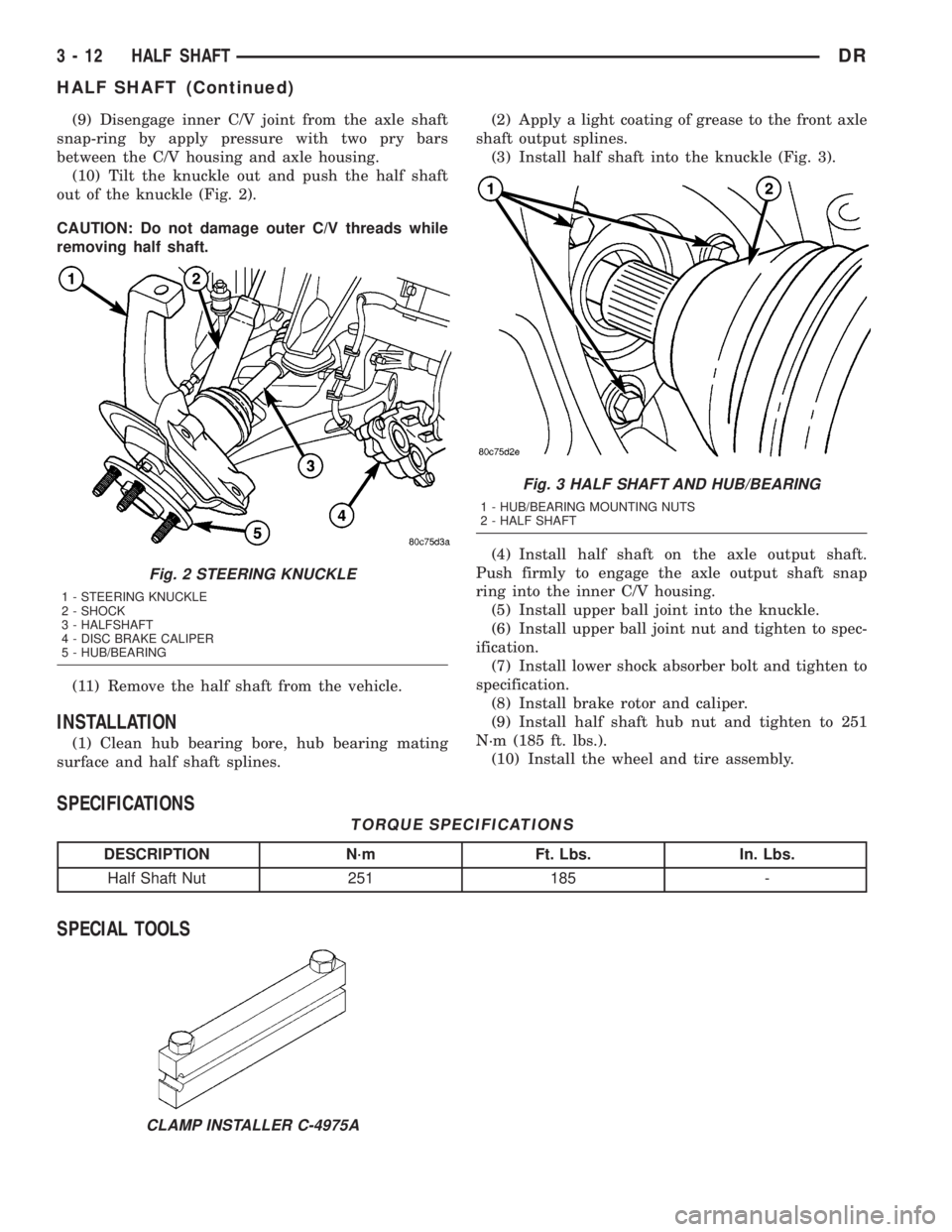
(10) Tilt the knuckle out and push the half shaft
out of the knuckle (Fig. 2).
CAUTION: Do not damage outer C/V threads while
removing half shaft.
(11) Remove the half shaft from the vehicle.
INSTALLATION
(1) Clean hub bearing bore, hub bearing mating
surface and half shaft splines.(2) Apply a light coating of grease to the front axle
shaft output splines.
(3) Install half shaft into the knuckle (Fig. 3).
(4) Install half shaft on the axle output shaft.
Push firmly to engage the axle output shaft snap
ring into the inner C/V housing.
(5) Install upper ball joint into the knuckle.
(6) Install upper ball joint nut and tighten to spec-
ification.
(7) Install lower shock absorber bolt and tighten to
specification.
(8) Install brake rotor and caliper.
(9) Install half shaft hub nut and tighten to 251
N´m (185 ft. lbs.).
(10) Install the wheel and tire assembly.
SPECIFICATIONS
TORQUE SPECIFICATIONS
DESCRIPTION N´m Ft. Lbs. In. Lbs.
Half Shaft Nut 251 185 -
SPECIAL TOOLS
Fig. 2 STEERING KNUCKLE
1 - STEERING KNUCKLE
2 - SHOCK
3 - HALFSHAFT
4 - DISC BRAKE CALIPER
5 - HUB/BEARING
Fig. 3 HALF SHAFT AND HUB/BEARING
1 - HUB/BEARING MOUNTING NUTS
2 - HALF SHAFT
CLAMP INSTALLER C-4975A
3 - 12 HALF SHAFTDR
HALF SHAFT (Continued)
Page 101 of 2895
(34) Zero dial indicator face to pointer.
(35) Push and hold ring gear downward while not
allowing the pinion gear to rotate. Dial indicator
reading should be between 0.12 mm (0.005 in.) and
0.20 mm (0.008 in.). If backlash is not within specifi-
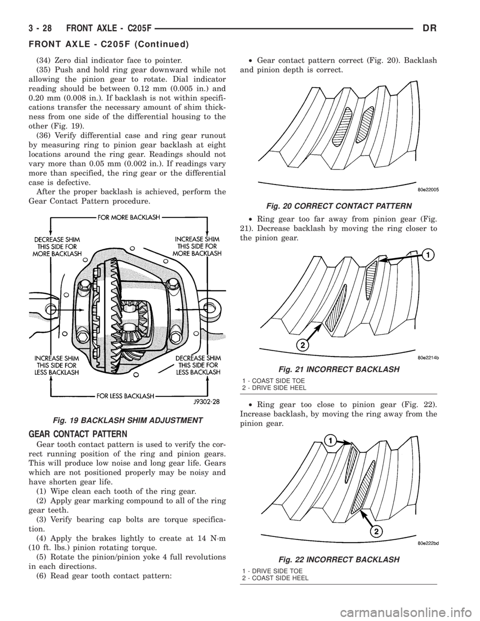
cations transfer the necessary amount of shim thick-
ness from one side of the differential housing to the
other (Fig. 19).
(36) Verify differential case and ring gear runout
by measuring ring to pinion gear backlash at eight
locations around the ring gear. Readings should not
vary more than 0.05 mm (0.002 in.). If readings vary
more than specified, the ring gear or the differential
case is defective.
After the proper backlash is achieved, perform the
Gear Contact Pattern procedure.
GEAR CONTACT PATTERN
Gear tooth contact pattern is used to verify the cor-
rect running position of the ring and pinion gears.
This will produce low noise and long gear life. Gears
which are not positioned properly may be noisy and
have shorten gear life.
(1) Wipe clean each tooth of the ring gear.
(2) Apply gear marking compound to all of the ring
gear teeth.
(3) Verify bearing cap bolts are torque specifica-
tion.
(4) Apply the brakes lightly to create at 14 N´m
(10 ft. lbs.) pinion rotating torque.
(5) Rotate the pinion/pinion yoke 4 full revolutions
in each directions.
(6) Read gear tooth contact pattern:²Gear contact pattern correct (Fig. 20). Backlash
and pinion depth is correct.
²Ring gear too far away from pinion gear (Fig.
21). Decrease backlash by moving the ring closer to
the pinion gear.
²Ring gear too close to pinion gear (Fig. 22).
Increase backlash, by moving the ring away from the
pinion gear.
Fig. 19 BACKLASH SHIM ADJUSTMENT
Fig. 20 CORRECT CONTACT PATTERN
Fig. 21 INCORRECT BACKLASH
1 - COAST SIDE TOE
2 - DRIVE SIDE HEEL
Fig. 22 INCORRECT BACKLASH
1 - DRIVE SIDE TOE
2 - COAST SIDE HEEL
3 - 28 FRONT AXLE - C205FDR
FRONT AXLE - C205F (Continued)
Page 124 of 2895
(6) Install ring gear side adjuster lock and bolt. Do
not tighten adjuster lock bolt at this time.
(7) Tighten pinion gear side adjuster firmly
against the differential case bearing cup.
(8) Rotate the pinion several times to seat the dif-
ferential bearings.
(9) Loosen pinion gear side adjuster until it is no
longer in contact with the bearing cup, then tighten
it until it makes contact.
(10) Tighten pinion gear side adjuster an addi-
tional:
²New Bearings:6 Adjuster Holes
²Original Bearings:4 Adjuster Holes
(11) Install pinion gear side adjuster lock and bolt.
Do not tighten adjuster lock bolt at this time.
(12) Tighten bearing cap bolts to 85 N´m (63 ft.
lbs.).
(13) Tighten adjuster lock bolts to 25 N´m (18 ft.
lbs.).
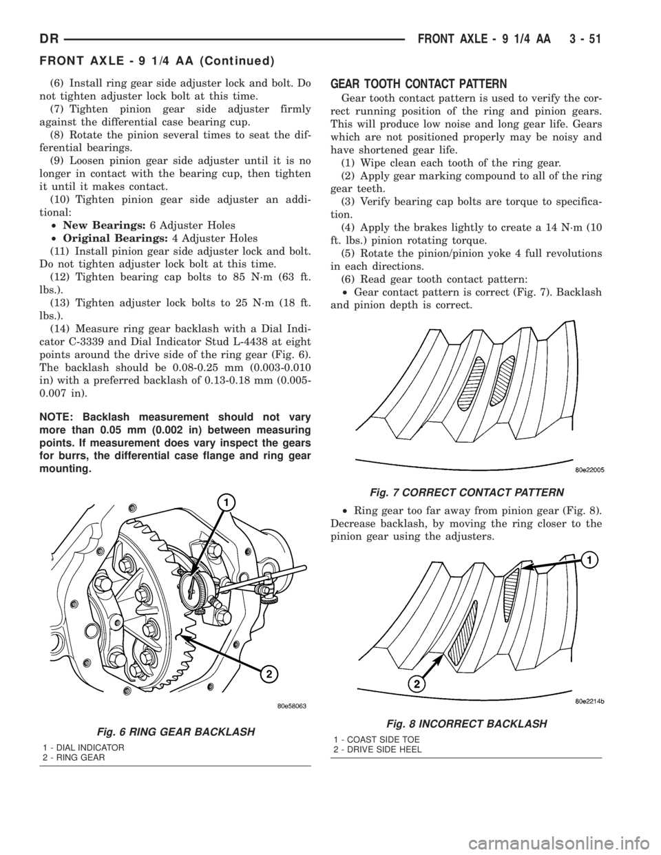
(14) Measure ring gear backlash with a Dial Indi-
cator C-3339 and Dial Indicator Stud L-4438 at eight
points around the drive side of the ring gear (Fig. 6).
The backlash should be 0.08-0.25 mm (0.003-0.010
in) with a preferred backlash of 0.13-0.18 mm (0.005-
0.007 in).
NOTE: Backlash measurement should not vary
more than 0.05 mm (0.002 in) between measuring
points. If measurement does vary inspect the gears
for burrs, the differential case flange and ring gear
mounting.GEAR TOOTH CONTACT PATTERN
Gear tooth contact pattern is used to verify the cor-
rect running position of the ring and pinion gears.
This will produce low noise and long gear life. Gears
which are not positioned properly may be noisy and
have shortened gear life.
(1) Wipe clean each tooth of the ring gear.
(2) Apply gear marking compound to all of the ring
gear teeth.
(3) Verify bearing cap bolts are torque to specifica-
tion.
(4) Apply the brakes lightly to create a 14 N´m (10
ft. lbs.) pinion rotating torque.
(5) Rotate the pinion/pinion yoke 4 full revolutions
in each directions.
(6) Read gear tooth contact pattern:
²Gear contact pattern is correct (Fig. 7). Backlash
and pinion depth is correct.
²Ring gear too far away from pinion gear (Fig. 8).
Decrease backlash, by moving the ring closer to the
pinion gear using the adjusters.
Fig. 6 RING GEAR BACKLASH
1 - DIAL INDICATOR
2 - RING GEAR
Fig. 7 CORRECT CONTACT PATTERN
Fig. 8 INCORRECT BACKLASH
1 - COAST SIDE TOE
2 - DRIVE SIDE HEEL
DRFRONT AXLE - 9 1/4 AA 3 - 51
FRONT AXLE - 9 1/4 AA (Continued)
Page 150 of 2895
(3) Rotate the ring gear to the position of the least
backlash. Mark the gear so that all future backlash
measurements will be taken with the same gear
teeth meshed.
(4) Loosen the right-side, tighten the left-side
threaded adjuster. Obtain backlash of 0.076 to 0.102
mm (0.003-0.004 in.) with each adjuster tightened to
14 N´m (10 ft. lbs.). Seat the bearing cups with the
procedure described above.
(5) Tighten the differential bearing cap bolts 136
N´m (100 ft. lbs.).
(6) Tighten the right-side threaded adjuster to 102
N´m (75 ft. lbs.). Seat the bearing cups with the pro-
cedure described above. Continue to tighten the
right-side adjuster and seat bearing cups until the
torque remains constant at 102 N´m (75 ft. lbs.)
(7) Measure the ring gear backlash. The range of
backlash is 0.15 to 0.203 mm (0.006 to 0.008 in.).
(8) Continue increasing the torque at the right-
side threaded adjuster until the specified backlash is
obtained.
NOTE: The left-side threaded adjuster torque
should have approximately 102 N´m (75 ft. lbs.). If
the torque is considerably less, the complete
adjustment procedure must be repeated.
(9) Tighten the left-side threaded adjuster until
102 N´m (75 ft. lbs.) torque is indicated. Seat the
bearing rollers with the procedure described above.
Do this until the torque remains constant.
(10) Install the threaded adjuster locks and
tighten the lock screws to 10 N´m (90 in. lbs.).GEAR CONTACT PATTERN
Gear tooth contact pattern is used to verify the cor-
rect running position of the ring and pinion gears.
This will produce low noise and long gear life. Gears
which are not positioned properly may be noisy and
have shorten gear life.
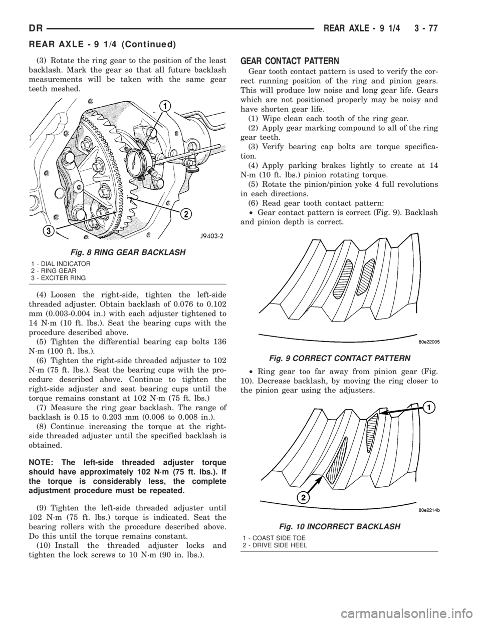
(1) Wipe clean each tooth of the ring gear.
(2) Apply gear marking compound to all of the ring
gear teeth.
(3) Verify bearing cap bolts are torque specifica-
tion.
(4) Apply parking brakes lightly to create at 14
N´m (10 ft. lbs.) pinion rotating torque.
(5) Rotate the pinion/pinion yoke 4 full revolutions
in each directions.
(6) Read gear tooth contact pattern:
²Gear contact pattern is correct (Fig. 9). Backlash
and pinion depth is correct.
²Ring gear too far away from pinion gear (Fig.
10). Decrease backlash, by moving the ring closer to
the pinion gear using the adjusters.
Fig. 8 RING GEAR BACKLASH
1 - DIAL INDICATOR
2 - RING GEAR
3 - EXCITER RING
Fig. 9 CORRECT CONTACT PATTERN
Fig. 10 INCORRECT BACKLASH
1 - COAST SIDE TOE
2 - DRIVE SIDE HEEL
DRREAR AXLE - 9 1/4 3 - 77
REAR AXLE - 9 1/4 (Continued)
Page 158 of 2895
(3) Coat the lip of thenewaxle seal with axle
lubricant and install with Installer C-4076-B and
Handle C-4735-1.
NOTE: When tool contacts the axle tube, the seal is
installed to the correct depth.
(4) Install the axle shaft.
(5) Install differential cover and fill with gear
lubricant to the bottom of the fill plug hole.
PINION SEAL
REMOVAL
(1) Mark universal joint, companion flange and
pinion shaft for installation reference.
(2) Remove propeller shaft from the companion
flange.
(3) Remove the brake rotors to prevent any drag.
(4) Rotate companion flange three or four times
and record pinion rotating torque with an inch pound
torque wrench.
(5) Install two bolts into the companion flange
threaded holes, 180É apart. Position Holder 6719A
against the companion flange and install and tighten
two bolts and washers into the remaining holes.
(6) Hold the companion flange with Holder 6719A
and remove pinion nut and washer.
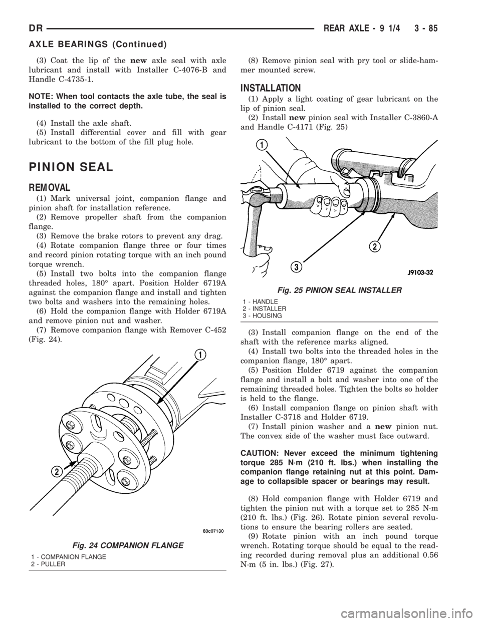
(7) Remove companion flange with Remover C-452
(Fig. 24).(8) Remove pinion seal with pry tool or slide-ham-
mer mounted screw.
INSTALLATION
(1) Apply a light coating of gear lubricant on the
lip of pinion seal.
(2) Installnewpinion seal with Installer C-3860-A
and Handle C-4171 (Fig. 25)
(3) Install companion flange on the end of the
shaft with the reference marks aligned.
(4) Install two bolts into the threaded holes in the
companion flange, 180É apart.
(5) Position Holder 6719 against the companion
flange and install a bolt and washer into one of the
remaining threaded holes. Tighten the bolts so holder
is held to the flange.
(6) Install companion flange on pinion shaft with
Installer C-3718 and Holder 6719.
(7) Install pinion washer and anewpinion nut.
The convex side of the washer must face outward.
CAUTION: Never exceed the minimum tightening
torque 285 N´m (210 ft. lbs.) when installing the
companion flange retaining nut at this point. Dam-
age to collapsible spacer or bearings may result.
(8) Hold companion flange with Holder 6719 and
tighten the pinion nut with a torque set to 285 N´m
(210 ft. lbs.) (Fig. 26). Rotate pinion several revolu-
tions to ensure the bearing rollers are seated.
(9) Rotate pinion with an inch pound torque
wrench. Rotating torque should be equal to the read-
ing recorded during removal plus an additional 0.56
N´m (5 in. lbs.) (Fig. 27).
Fig. 24 COMPANION FLANGE
1 - COMPANION FLANGE
2 - PULLER
Fig. 25 PINION SEAL INSTALLER
1 - HANDLE
2 - INSTALLER
3 - HOUSING
DRREAR AXLE - 9 1/4 3 - 85
AXLE BEARINGS (Continued)
Page 179 of 2895
(12) Tighten bearing cap bolts to 115 N´m (85 ft.
lbs.).
(13) Tighten adjuster lock bolts to 33 N´m (24 ft.
lbs.).
(14) Measure ring gear backlash with a Dial Indi-
cator C-3339 and Dial Indicator Stud L-4438 at eight
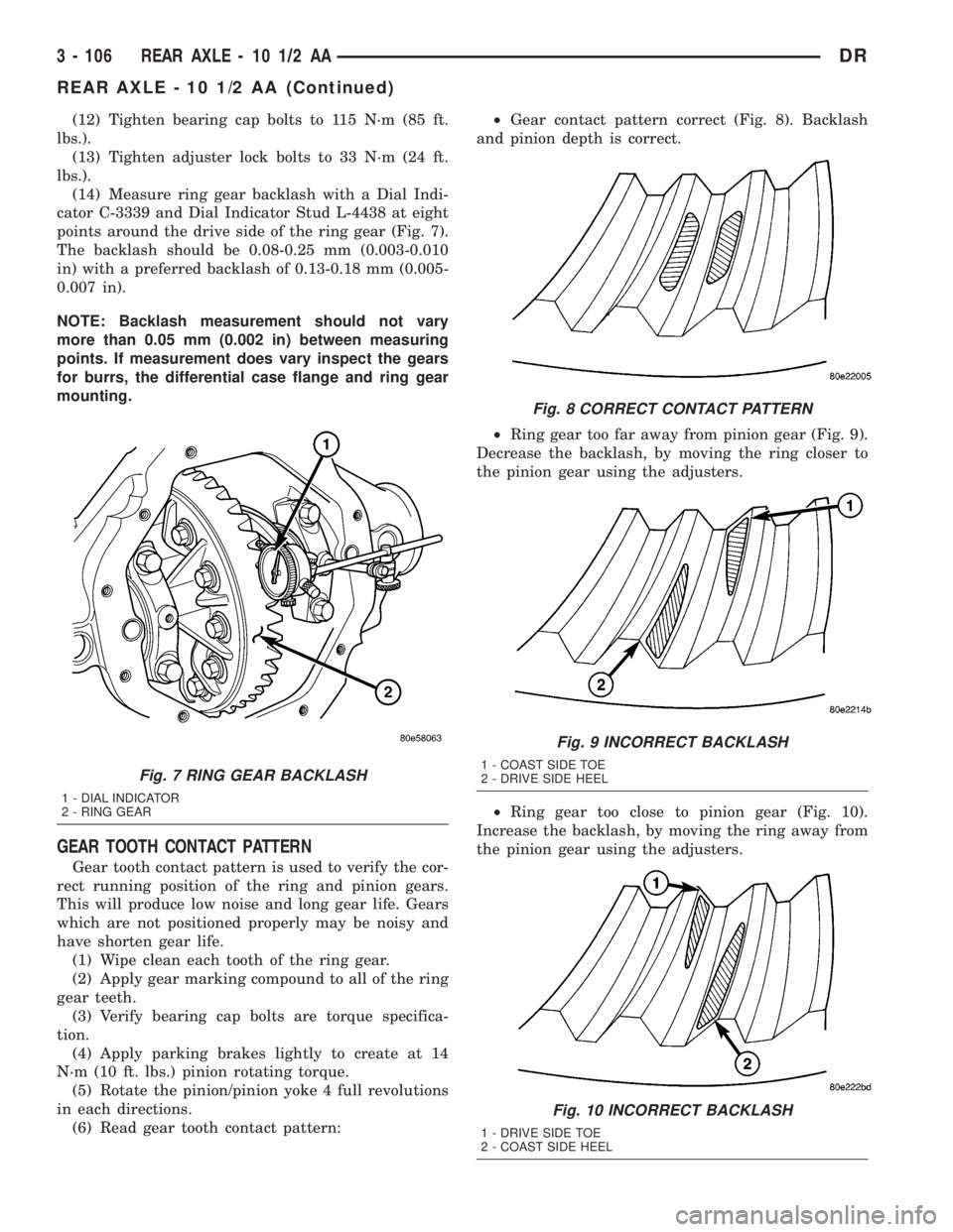
points around the drive side of the ring gear (Fig. 7).
The backlash should be 0.08-0.25 mm (0.003-0.010
in) with a preferred backlash of 0.13-0.18 mm (0.005-
0.007 in).
NOTE: Backlash measurement should not vary
more than 0.05 mm (0.002 in) between measuring
points. If measurement does vary inspect the gears
for burrs, the differential case flange and ring gear
mounting.
GEAR TOOTH CONTACT PATTERN
Gear tooth contact pattern is used to verify the cor-
rect running position of the ring and pinion gears.
This will produce low noise and long gear life. Gears
which are not positioned properly may be noisy and
have shorten gear life.
(1) Wipe clean each tooth of the ring gear.
(2) Apply gear marking compound to all of the ring
gear teeth.
(3) Verify bearing cap bolts are torque specifica-
tion.
(4) Apply parking brakes lightly to create at 14
N´m (10 ft. lbs.) pinion rotating torque.
(5) Rotate the pinion/pinion yoke 4 full revolutions
in each directions.
(6) Read gear tooth contact pattern:²Gear contact pattern correct (Fig. 8). Backlash
and pinion depth is correct.
²Ring gear too far away from pinion gear (Fig. 9).
Decrease the backlash, by moving the ring closer to
the pinion gear using the adjusters.
²Ring gear too close to pinion gear (Fig. 10).
Increase the backlash, by moving the ring away from
the pinion gear using the adjusters.
Fig. 7 RING GEAR BACKLASH
1 - DIAL INDICATOR
2 - RING GEAR
Fig. 8 CORRECT CONTACT PATTERN
Fig. 9 INCORRECT BACKLASH
1 - COAST SIDE TOE
2 - DRIVE SIDE HEEL
Fig. 10 INCORRECT BACKLASH
1 - DRIVE SIDE TOE
2 - COAST SIDE HEEL
3 - 106 REAR AXLE - 10 1/2 AADR
REAR AXLE - 10 1/2 AA (Continued)
Page 192 of 2895
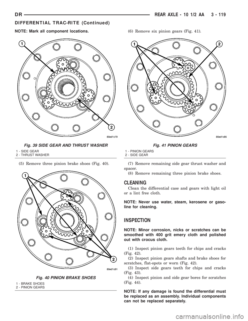
NOTE: Mark all component locations.
(5) Remove three pinion brake shoes (Fig. 40).(6) Remove six pinion gears (Fig. 41).
(7) Remove remaining side gear thrust washer and
spacer.
(8) Remove remaining three pinion brake shoes.
CLEANING
Clean the differential case and gears with light oil
or a lint free cloth.
NOTE: Never use water, steam, kerosene or gaso-
line for cleaning.
INSPECTION
NOTE: Minor corrosion, nicks or scratches can be
smoothed with 400 grit emery cloth and polished
out with crocus cloth.
(1) Inspect pinion gears teeth for chips and cracks
(Fig. 42).
(2) Inspect pinion gears shafts and brake shoes for
scratches, flat-spots or worn (Fig. 42).
(3) Inspect side gears teeth for chips and cracks
(Fig. 43).
(4) Inspect pinion and side gear bores for scratches
(Fig. 44).
NOTE: If any damage is found the differential must
be replaced as an assembly. Individual components
can not be replaced separately.
Fig. 39 SIDE GEAR AND THRUST WASHER
1 - SIDE GEAR
2 - THRUST WASHER
Fig. 40 PINION BRAKE SHOES
1 - BRAKE SHOES
2 - PINION GEARS
Fig. 41 PINION GEARS
1 - PINION GEARS
2 - SIDE GEAR
DRREAR AXLE - 10 1/2 AA 3 - 119
DIFFERENTIAL TRAC-RITE (Continued)
Page 206 of 2895
(12) Tighten bearing cap bolts to 115 N´m (85 ft.
lbs.).
(13) Tighten adjuster lock bolts to 33 N´m (24 ft.
lbs.).
(14) Measure ring gear backlash with a Dial Indi-
cator C-3339 and Dial Indicator Stud L-4438 at eight
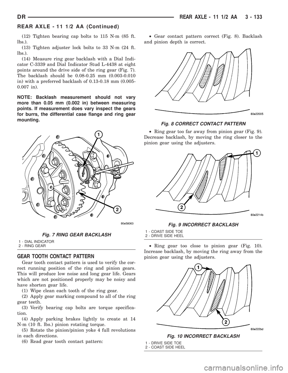
points around the drive side of the ring gear (Fig. 7).
The backlash should be 0.08-0.25 mm (0.003-0.010
in) with a preferred backlash of 0.13-0.18 mm (0.005-
0.007 in).
NOTE: Backlash measurement should not vary
more than 0.05 mm (0.002 in) between measuring
points. If measurement does vary inspect the gears
for burrs, the differential case flange and ring gear
mounting.
GEAR TOOTH CONTACT PATTERN
Gear tooth contact pattern is used to verify the cor-
rect running position of the ring and pinion gears.
This will produce low noise and long gear life. Gears
which are not positioned properly may be noisy and
have shorten gear life.
(1) Wipe clean each tooth of the ring gear.
(2) Apply gear marking compound to all of the ring
gear teeth.
(3) Verify bearing cap bolts are torque specifica-
tion.
(4) Apply parking brakes lightly to create at 14
N´m (10 ft. lbs.) pinion rotating torque.
(5) Rotate the pinion/pinion yoke 4 full revolutions
in each directions.
(6) Read gear tooth contact pattern:²Gear contact pattern correct (Fig. 8). Backlash
and pinion depth is correct.
²Ring gear too far away from pinion gear (Fig. 9).
Decrease backlash, by moving the ring closer to the
pinion gear using the adjusters.
²Ring gear too close to pinion gear (Fig. 10).
Increase backlash, by moving the ring away from the
pinion gear using the adjusters.
Fig. 7 RING GEAR BACKLASH
1 - DIAL INDICATOR
2 - RING GEAR
Fig. 8 CORRECT CONTACT PATTERN
Fig. 9 INCORRECT BACKLASH
1 - COAST SIDE TOE
2 - DRIVE SIDE HEEL
Fig. 10 INCORRECT BACKLASH
1 - DRIVE SIDE TOE
2 - COAST SIDE HEEL
DRREAR AXLE - 11 1/2 AA 3 - 133
REAR AXLE - 11 1/2 AA (Continued)