coolant capacity DODGE RAM 2003 Service Repair Manual
[x] Cancel search | Manufacturer: DODGE, Model Year: 2003, Model line: RAM, Model: DODGE RAM 2003Pages: 2895, PDF Size: 83.15 MB
Page 18 of 2895
FLUID ADDITIVES
DaimlerChrysler strongly recommends against the
addition of any fluids to the transmission, other than
those automatic transmission fluids listed above.
Exceptions to this policy are the use of special dyes
to aid in detecting fluid leaks.
Various ªspecialº additives and supplements exist
that claim to improve shift feel and/or quality. These
additives and others also claim to improve converter
clutch operation and inhibit overheating, oxidation,
varnish, and sludge. These claims have not been sup-
ported to the satisfaction of DaimlerChrysler and
these additivesmust not be used.The use of trans-
mission ªsealersº should also be avoided, since they
may adversely affect the integrity of transmission
seals.
OPERATION - AUTOMATIC TRANSMISSION
FLUID
The automatic transmission fluid is selected based
upon several qualities. The fluid must provide a high
level of protection for the internal components by
providing a lubricating film between adjacent metal
components. The fluid must also be thermally stable
so that it can maintain a consistent viscosity through
a large temperature range. If the viscosity stays con-
stant through the temperature range of operation,
transmission operation and shift feel will remain con-
sistent. Transmission fluid must also be a good con-
ductor of heat. The fluid must absorb heat from the
internal transmission components and transfer that
heat to the transmission case.
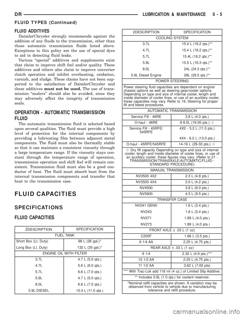
FLUID CAPACITIES
SPECIFICATIONS
FLUID CAPACITIES
2DESCRIPTIONSPECIFICATION
FUEL TANK
Short Box (Lt. Duty) 98 L (26 gal.)*
Long Box (Lt. Duty) 132 L (35 gal.)*
ENGINE OIL WITH FILTER
3.7L 4.7 L (5.0 qts.)
4.7L 5.6 L (6.0 qts.)
5.7L 6.6 L (7.0 qts.)
5.9L 4.7 L (5.0 qts.)
8.0L 6.6 L (7.0 qts.)
5.9L DIESEL 10.4 L (11.0 qts.)
2DESCRIPTION SPECIFICATION
COOLING SYSTEM
3.7L 15.4 L (16.2 qts.)**
4.7L 15.4 L (16.2 qts.)**
5.7L 15.4L (16.2 qts.)**
5.9L 15.5 L (16.3 qts.)**
8.0L 24L (24.3 qts.)**
5.9L Diesel Engine 28L (29.5 qts.)**
POWER STEERING
Power steering fluid capacities are dependent on engine/
chassis options as well as steering gear/cooler options.
Depending on type and size of internal cooler, length and
inside diameter of cooler lines, or use of an auxiliary cooler,
these capacities may vary. Refer to 19, Steering for proper
fill and bleed procedures.
AUTOMATIC TRANSMISSION
Service Fill - 46RE 3.8 L (4.0 qts.)
O-haul - 46RE 9-9.5L (19-20 pts.)L
Service Fill - 45RFE/
545RFE4X2 - 5.2 L (11.0 pts.)
4X4 - 6.2 L (13.0 pts.)
O-haul - 45RFE/545RFE 14-16 L (29-33 pts.)L
LDry fill capacity Depending on type and size of internal
cooler, length and inside diameter of cooler lines, or use of
an auxiliary cooler, these figures may vary. (Refer to 21 -
TRANSMISSION/TRANSAXLE/AUTOMATIC/FLUID -
STANDARD PROCEDURE)
MANUAL TRANSMISSION
NV3500 4X2 2.3 L (4.8 pts.)
NV3500 4X4 2.0 L (4.2 pts.)
NV4500 3.8 L (8.0 pts.)
NV5600 4.5 L (9.5 pts.)
TRANSFER CASE
NV241 GENII 1.6 L (3.4 pts.)
NV243 1.6 L (3.4 pts.)
NV271 1.89 L (4.0 pts.)
NV273 1.89 L (4.0 pts.)
FRONT AXLE .03 L (1 oz)
C205F 1.66 L (3.5 pts.)
9 1/4 AA 2.25 L (4.75 pts.)
REAR AXLE .03 L (1 oz)
9 1/4 2.32 L (4.9 pts.)***
10 1/2 AA 2.25 L (4.75 pts.)
11 1/2 AA 3.62 L (7.65 pts)
*** With Trac-Lok add 118 ml (4 oz.) of Limited Slip Additive.
** Includes 0.9L (1.0 qts.) for coolant reservoir.
*Nominal refill capacities are shown. A variation may be
observed from vehicle to vehicle due to manufacturing
tolerance and refill procedure.
DRLUBRICATION & MAINTENANCE 0 - 5
FLUID TYPES (Continued)
Page 288 of 2895
COOLING
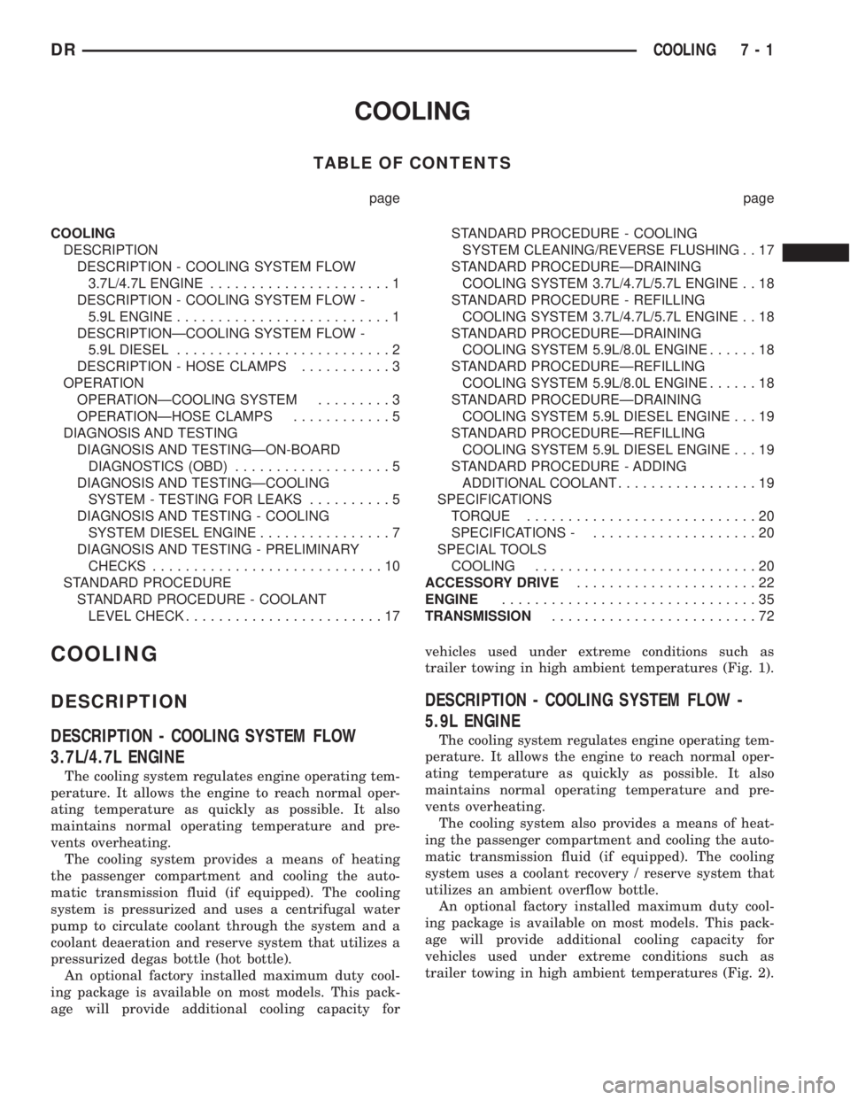
TABLE OF CONTENTS
page page
COOLING
DESCRIPTION
DESCRIPTION - COOLING SYSTEM FLOW
3.7L/4.7L ENGINE......................1
DESCRIPTION - COOLING SYSTEM FLOW -
5.9L ENGINE..........................1
DESCRIPTIONÐCOOLING SYSTEM FLOW -
5.9L DIESEL..........................2
DESCRIPTION - HOSE CLAMPS...........3
OPERATION
OPERATIONÐCOOLING SYSTEM.........3
OPERATIONÐHOSE CLAMPS............5
DIAGNOSIS AND TESTING
DIAGNOSIS AND TESTINGÐON-BOARD
DIAGNOSTICS (OBD)...................5
DIAGNOSIS AND TESTINGÐCOOLING
SYSTEM - TESTING FOR LEAKS..........5
DIAGNOSIS AND TESTING - COOLING
SYSTEM DIESEL ENGINE................7
DIAGNOSIS AND TESTING - PRELIMINARY
CHECKS............................10
STANDARD PROCEDURE
STANDARD PROCEDURE - COOLANT
LEVEL CHECK........................17STANDARD PROCEDURE - COOLING
SYSTEM CLEANING/REVERSE FLUSHING . . 17
STANDARD PROCEDUREÐDRAINING
COOLING SYSTEM 3.7L/4.7L/5.7L ENGINE . . 18
STANDARD PROCEDURE - REFILLING
COOLING SYSTEM 3.7L/4.7L/5.7L ENGINE . . 18
STANDARD PROCEDUREÐDRAINING
COOLING SYSTEM 5.9L/8.0L ENGINE......18
STANDARD PROCEDUREÐREFILLING
COOLING SYSTEM 5.9L/8.0L ENGINE......18
STANDARD PROCEDUREÐDRAINING
COOLING SYSTEM 5.9L DIESEL ENGINE . . . 19
STANDARD PROCEDUREÐREFILLING
COOLING SYSTEM 5.9L DIESEL ENGINE . . . 19
STANDARD PROCEDURE - ADDING
ADDITIONAL COOLANT.................19
SPECIFICATIONS
TORQUE............................20
SPECIFICATIONS -....................20
SPECIAL TOOLS
COOLING...........................20
ACCESSORY DRIVE......................22
ENGINE...............................35
TRANSMISSION.........................72
COOLING
DESCRIPTION
DESCRIPTION - COOLING SYSTEM FLOW
3.7L/4.7L ENGINE
The cooling system regulates engine operating tem-
perature. It allows the engine to reach normal oper-
ating temperature as quickly as possible. It also
maintains normal operating temperature and pre-
vents overheating.
The cooling system provides a means of heating
the passenger compartment and cooling the auto-
matic transmission fluid (if equipped). The cooling
system is pressurized and uses a centrifugal water
pump to circulate coolant through the system and a
coolant deaeration and reserve system that utilizes a
pressurized degas bottle (hot bottle).
An optional factory installed maximum duty cool-
ing package is available on most models. This pack-
age will provide additional cooling capacity forvehicles used under extreme conditions such as
trailer towing in high ambient temperatures (Fig. 1).
DESCRIPTION - COOLING SYSTEM FLOW -
5.9L ENGINE
The cooling system regulates engine operating tem-
perature. It allows the engine to reach normal oper-
ating temperature as quickly as possible. It also
maintains normal operating temperature and pre-
vents overheating.
The cooling system also provides a means of heat-
ing the passenger compartment and cooling the auto-
matic transmission fluid (if equipped). The cooling
system uses a coolant recovery / reserve system that
utilizes an ambient overflow bottle.
An optional factory installed maximum duty cool-
ing package is available on most models. This pack-
age will provide additional cooling capacity for
vehicles used under extreme conditions such as
trailer towing in high ambient temperatures (Fig. 2).
DRCOOLING 7 - 1
Page 292 of 2895
system is pressurized and uses a centrifugal water
pump to circulate coolant throughout the system.
5.9L, 5.9L Diesel, and 8.0L engines utilize an
ambient overflow bottle for coolant recovery/reserve.
The 3.7L and 4.7L engines utilize a pressurized
degas bottle for coolant deaeration and reserve. This
degas bottle has coolant flowing through it continu-
ously, supplied by a vent in the hot side radiator
tank and returning to the heater return hose.
An optional factory installed maximum duty cool-
ing package is available on most models. This pack-
age will provide additional cooling capacity for
vehicles used under extreme conditions such as
trailer towing in high ambient temperatures.
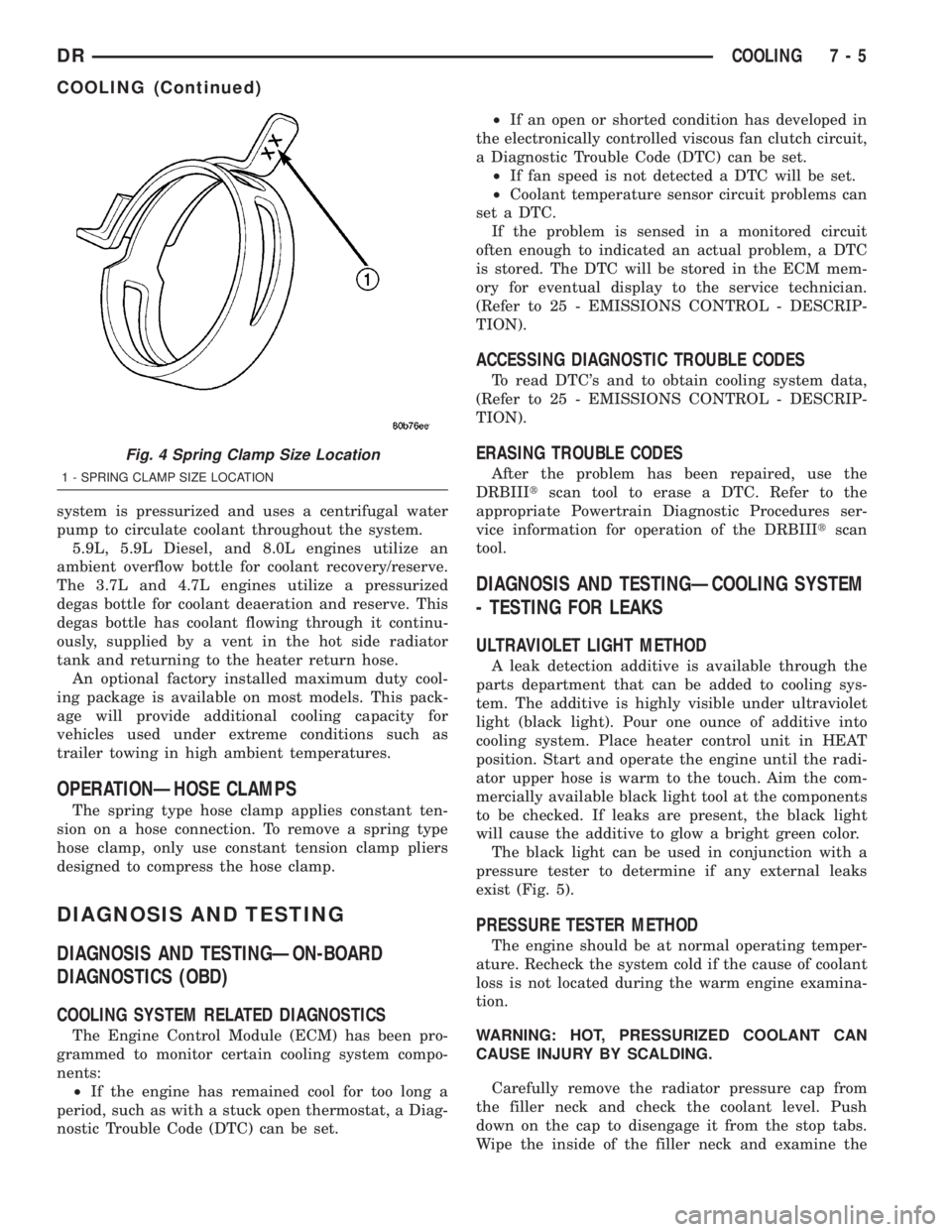
OPERATIONÐHOSE CLAMPS
The spring type hose clamp applies constant ten-
sion on a hose connection. To remove a spring type
hose clamp, only use constant tension clamp pliers
designed to compress the hose clamp.
DIAGNOSIS AND TESTING
DIAGNOSIS AND TESTINGÐON-BOARD
DIAGNOSTICS (OBD)
COOLING SYSTEM RELATED DIAGNOSTICS
The Engine Control Module (ECM) has been pro-
grammed to monitor certain cooling system compo-
nents:
²If the engine has remained cool for too long a
period, such as with a stuck open thermostat, a Diag-
nostic Trouble Code (DTC) can be set.²If an open or shorted condition has developed in
the electronically controlled viscous fan clutch circuit,
a Diagnostic Trouble Code (DTC) can be set.
²If fan speed is not detected a DTC will be set.
²Coolant temperature sensor circuit problems can
set a DTC.
If the problem is sensed in a monitored circuit
often enough to indicated an actual problem, a DTC
is stored. The DTC will be stored in the ECM mem-
ory for eventual display to the service technician.
(Refer to 25 - EMISSIONS CONTROL - DESCRIP-
TION).
ACCESSING DIAGNOSTIC TROUBLE CODES
To read DTC's and to obtain cooling system data,
(Refer to 25 - EMISSIONS CONTROL - DESCRIP-
TION).
ERASING TROUBLE CODES
After the problem has been repaired, use the
DRBIIItscan tool to erase a DTC. Refer to the
appropriate Powertrain Diagnostic Procedures ser-
vice information for operation of the DRBIIItscan
tool.
DIAGNOSIS AND TESTINGÐCOOLING SYSTEM
- TESTING FOR LEAKS
ULTRAVIOLET LIGHT METHOD
A leak detection additive is available through the
parts department that can be added to cooling sys-
tem. The additive is highly visible under ultraviolet
light (black light). Pour one ounce of additive into
cooling system. Place heater control unit in HEAT
position. Start and operate the engine until the radi-
ator upper hose is warm to the touch. Aim the com-
mercially available black light tool at the components
to be checked. If leaks are present, the black light
will cause the additive to glow a bright green color.
The black light can be used in conjunction with a
pressure tester to determine if any external leaks
exist (Fig. 5).
PRESSURE TESTER METHOD
The engine should be at normal operating temper-
ature. Recheck the system cold if the cause of coolant
loss is not located during the warm engine examina-
tion.
WARNING: HOT, PRESSURIZED COOLANT CAN
CAUSE INJURY BY SCALDING.
Carefully remove the radiator pressure cap from
the filler neck and check the coolant level. Push
down on the cap to disengage it from the stop tabs.
Wipe the inside of the filler neck and examine the
Fig. 4 Spring Clamp Size Location
1 - SPRING CLAMP SIZE LOCATION
DRCOOLING 7 - 5
COOLING (Continued)
Page 339 of 2895
ENGINE COOLANT
THERMOSTAT - 5.9L DIESEL
DESCRIPTION
CAUTION: Do not operate an engine without a ther-
mostat, except for servicing or testing. An engine
with the thermostat removed will operate in the
radiator bypass mode, causing an overheat condi-
tion.
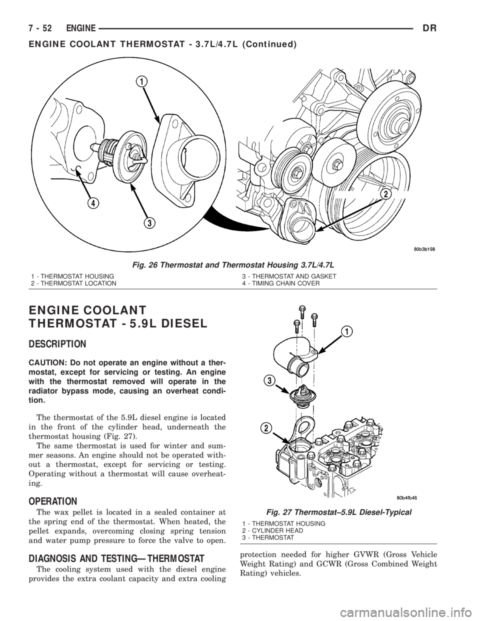
The thermostat of the 5.9L diesel engine is located
in the front of the cylinder head, underneath the
thermostat housing (Fig. 27).
The same thermostat is used for winter and sum-
mer seasons. An engine should not be operated with-
out a thermostat, except for servicing or testing.
Operating without a thermostat will cause overheat-
ing.
OPERATION
The wax pellet is located in a sealed container at
the spring end of the thermostat. When heated, the
pellet expands, overcoming closing spring tension
and water pump pressure to force the valve to open.
DIAGNOSIS AND TESTINGÐTHERMOSTAT
The cooling system used with the diesel engine
provides the extra coolant capacity and extra coolingprotection needed for higher GVWR (Gross Vehicle
Weight Rating) and GCWR (Gross Combined Weight
Rating) vehicles.
Fig. 26 Thermostat and Thermostat Housing 3.7L/4.7L
1 - THERMOSTAT HOUSING
2 - THERMOSTAT LOCATION3 - THERMOSTAT AND GASKET
4 - TIMING CHAIN COVER
Fig. 27 Thermostat±5.9L Diesel-Typical
1 - THERMOSTAT HOUSING
2 - CYLINDER HEAD
3 - THERMOSTAT
7 - 52 ENGINEDR
ENGINE COOLANT THERMOSTAT - 3.7L/4.7L (Continued)
Page 340 of 2895
This system capacity will not effect warm up or
cold weather operating characteristics if the thermo-
stat is operating properly. This is because coolant
will be held in the engine until it reaches the ther-
mostat ªsetº temperature.
Diesel engines, due to their inherent efficiency are
slower to warm up than gasoline powered engines,
and will operate at lower temperatures when the
vehicle is unloaded. Because of this, lower tempera-
ture gauge readings for diesel versus gasoline
engines may, at times be normal.
Typically, complaints of low engine coolant temper-
ature are observed as low heater output when com-
bined with cool or cold outside temperatures.
To help promote faster engine warm-up, the elec-
tric engine block heater must be used with cool or
cold outside temperatures. This will help keep the
engine coolant warm when the vehicle is parked. Use
the block heater if the outside temperature is below
4ÉC (40ÉF).Do not use the block heater if the
outside temperature is above 4ÉC (40ÉF).
A ªCold Weather Coverº is available from the parts
department through the Mopar Accessories product
line. This accessory cover is designed to block airflow
entering the radiator and engine compartment to
promote faster engine warm-up. It attaches to the
front of the vehicle at the grill opening.The cover is
to be used with cool or cold temperatures only.
If used with high outside temperatures, serious
engine damage could result.Refer to the litera-
ture supplied with the cover for additional informa-
tion.
(1) To determine if the thermostat is defective, it
must be removed from the vehicle (Refer to 7 -
COOLING/ENGINE/ENGINE COOLANT THERMO-
STAT - REMOVAL).
(2) After the thermostat has been removed, exam-
ine the thermostat and inside of thermostat housing
for contaminants. If contaminants are found, the
thermostat may already be in a ªstuck openº position.
Flush the cooling system before replacing thermostat
(Refer to 7 - COOLING - STANDARD PROCE-
DURE).
(3) Place the thermostat into a container filled
with water.
(4) Place the container on a hot plate or other suit-
able heating device.
(5) Place a commercially available radiator ther-
mometer into the water.
(6) Apply heat to the water while observing the
thermostat and thermometer.
(7) The thermostat will begin to open at 85.5 Ð
89.4ÉC. (186 Ð193ÉF ). If the valve starts to move
before this temperature is reached, it is opening too
early. Replace thermostat. The thermostat should be
fully open (valve will stop moving) at 97ÉC (207ÉF). Ifthe valve is still moving when the water temperature
reaches 97ÉC (207ÉF), it is opening too late. Replace
thermostat. If the valve refuses to move at any time,
replace thermostat.
REMOVAL
WARNING: DO NOT LOOSEN THE RADIATOR
DRAINCOCK WITH THE SYSTEM HOT AND PRES-
SURIZED. SERIOUS BURNS FROM THE COOLANT
CAN OCCUR.
Do not waste reusable coolant. If the solution is
clean, drain the coolant into a clean container for
reuse.
(1) Disconnect the battery negative cables.
(2) Drain cooling system until coolant level is
below thermostat (Refer to 7 - COOLING - STAN-
DARD PROCEDURE).
WARNING: CONSTANT TENSION HOSE CLAMPS
ARE USED ON MOST COOLING SYSTEM HOSES.
WHEN REMOVING OR INSTALLING, USE ONLY
TOOLS DESIGNED FOR SERVICING THIS TYPE OF
CLAMP, SUCH AS SPECIAL CLAMP TOOL (NUMBER
6094). SNAP-ON CLAMP TOOL (NUMBER HPC-20)
MAY BE USED FOR LARGER CLAMPS. ALWAYS
WEAR SAFETY GLASSES WHEN SERVICING CON-
STANT TENSION CLAMPS.
CAUTION: A number or letter is stamped into the
tongue of constant tension clamps. If replacement
is necessary, use only an original equipment clamp
with a matching number or letter.
(3) Remove radiator hose clamp and hose from
thermostat housing.
(4) Remove the three (3) water outlet-to-cylinder
head bolts and remove the water outlet connector
(Fig. 28).
(5) Clean the mating surfaces of the water outlet
connector and clean the thermostat seat groove at
the top of the thermostat housing (Fig. 28).
INSTALLATION
(1) Inspect thermostat seal for cuts or nicks.
Replace if damaged.
(2) Install the thermostat into the groove in the
top of the cylinder head (Fig. 28).
(3) Install the thermostat housing and bolts.
Tighten the bolts to 10 N´m (88 in. lbs.) torque.
(4) Install the radiator upper hose and clamp.
(5) Fill the cooling system with coolant (Refer to 7
- COOLING - STANDARD PROCEDURE).
(6) Connect the battery negative cables.
DRENGINE 7 - 53
ENGINE COOLANT THERMOSTAT - 5.9L DIESEL (Continued)
Page 347 of 2895
(6) Remove the power steering cooler mounting
bolts and position the power steering cooler out of
the way.
(7) Disconnect the transmission cooler lines at the
transmission. The transmission cooler will remain on
the radiator and can be removed as an assembly.
(8) Remove the lower shroud assembly and the
electronic viscous fan wiring from the upper shroud
assembly.
(9) Remove the two radiator upper mounting bolts
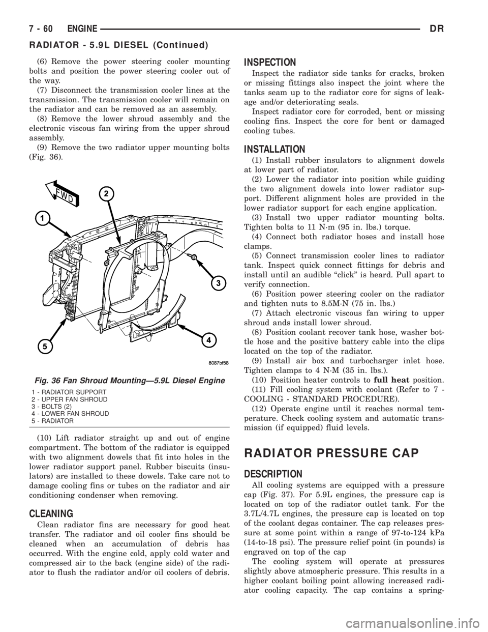
(Fig. 36).
(10) Lift radiator straight up and out of engine
compartment. The bottom of the radiator is equipped
with two alignment dowels that fit into holes in the
lower radiator support panel. Rubber biscuits (insu-
lators) are installed to these dowels. Take care not to
damage cooling fins or tubes on the radiator and air
conditioning condenser when removing.
CLEANING
Clean radiator fins are necessary for good heat
transfer. The radiator and oil cooler fins should be
cleaned when an accumulation of debris has
occurred. With the engine cold, apply cold water and
compressed air to the back (engine side) of the radi-
ator to flush the radiator and/or oil coolers of debris.
INSPECTION
Inspect the radiator side tanks for cracks, broken
or missing fittings also inspect the joint where the
tanks seam up to the radiator core for signs of leak-
age and/or deteriorating seals.
Inspect radiator core for corroded, bent or missing
cooling fins. Inspect the core for bent or damaged
cooling tubes.
INSTALLATION
(1) Install rubber insulators to alignment dowels
at lower part of radiator.
(2) Lower the radiator into position while guiding
the two alignment dowels into lower radiator sup-
port. Different alignment holes are provided in the
lower radiator support for each engine application.
(3) Install two upper radiator mounting bolts.
Tighten bolts to 11 N´m (95 in. lbs.) torque.
(4) Connect both radiator hoses and install hose
clamps.
(5) Connect transmission cooler lines to radiator
tank. Inspect quick connect fittings for debris and
install until an audible ªclickº is heard. Pull apart to
verify connection.
(6) Position power steering cooler on the radiator
and tighten nuts to 8.5M´N (75 in. lbs.)
(7) Attach electronic viscous fan wiring to upper
shroud ands install lower shroud.
(8) Position coolant recover tank hose, washer bot-
tle hose and the positive battery cable into the clips
located on the top of the radiator.
(9) Install air box and turbocharger inlet hose.
Tighten clamps to 4 N´M (35 in. lbs.).
(10) Position heater controls tofull heatposition.
(11) Fill cooling system with coolant (Refer to 7 -
COOLING - STANDARD PROCEDURE).
(12) Operate engine until it reaches normal tem-
perature. Check cooling system and automatic trans-
mission (if equipped) fluid levels.
RADIATOR PRESSURE CAP
DESCRIPTION
All cooling systems are equipped with a pressure
cap (Fig. 37). For 5.9L engines, the pressure cap is
located on top of the radiator outlet tank. For the
3.7L/4.7L engines, the pressure cap is located on top
of the coolant degas container. The cap releases pres-
sure at some point within a range of 97-to-124 kPa
(14-to-18 psi). The pressure relief point (in pounds) is
engraved on top of the cap
The cooling system will operate at pressures
slightly above atmospheric pressure. This results in a
higher coolant boiling point allowing increased radi-
ator cooling capacity. The cap contains a spring-
Fig. 36 Fan Shroud MountingÐ5.9L Diesel Engine
1 - RADIATOR SUPPORT
2 - UPPER FAN SHROUD
3 - BOLTS (2)
4 - LOWER FAN SHROUD
5 - RADIATOR
7 - 60 ENGINEDR
RADIATOR - 5.9L DIESEL (Continued)
Page 2861 of 2895

CARDAN UNIVERSAL JOINTS -
DISASSEMBLY, SINGLE..................3-9
CARGO BOX - INSTALLATION...........23-37
CARGO BOX - REMOVAL...............23-37
CARGO BOX - TIE DOWN -
INSTALLATION.......................23-37
CARGO BOX - TIE DOWN - REMOVAL....23-37
CARGO LAMP INDICATOR -
DESCRIPTION.......................8J-20
CARGO LAMP INDICATOR - OPERATION . . 8J-20
CARPETS AND FLOOR MATS -
INSTALLATION.......................23-66
CARPETS AND FLOOR MATS - REMOVAL . 23-66
CASCADE OVERFLOW VALVE -
DESCRIPTION.......................14-77
CASCADE OVERFLOW VALVE -
OPERATION.........................14-77
CASE - NV241 GENII - ASSEMBLY,
TRANSFER.........................21-604
CASE - NV241 GENII - CLEANING,
TRANSFER.........................21-602
CASE - NV241 GENII - DESCRIPTION,
TRANSFER............................0-4
CASE - NV241 GENII - DESCRIPTION,
TRANSFER.........................21-591
CASE - NV241 GENII - DIAGNOSIS AND
TESTING, TRANSFER.................21-592
CASE - NV241 GENII - DISASSEMBLY,
TRANSFER.........................21-593
CASE - NV241 GENII - INSPECTION,
TRANSFER.........................21-602
CASE - NV241 GENII - INSTALLATION,
TRANSFER.........................21-614
CASE - NV241 GENII - OPERATION,
TRANSFER.........................21-591
CASE - NV241 GENII - REMOVAL,
TRANSFER.........................21-593
CASE - NV243 - ASSEMBLY, TRANSFER . . 21-670
CASE - NV243 - CLEANING, TRANSFER . . 21-668
CASE - NV243 - DESCRIPTION,
TRANSFER............................0-4
CASE - NV243 - DESCRIPTION,
TRANSFER.........................21-658
CASE - NV243 - DIAGNOSIS AND
TESTING, TRANSFER.................21-659
CASE - NV243 - DISASSEMBLY,
TRANSFER.........................21-660
CASE - NV243 - INSPECTION, TRANSFER . 21-668
CASE - NV243 - INSTALLATION,
TRANSFER.........................21-679
CASE - NV243 - OPERATION, TRANSFER . 21-659
CASE - NV243 - REMOVAL, TRANSFER . . 21-660
CASE - NV271 - ASSEMBLY, TRANSFER . . 21-637
CASE - NV271 - CLEANING, TRANSFER . . 21-635
CASE - NV271 - DESCRIPTION,
TRANSFER............................0-4
CASE - NV271 - DESCRIPTION,
TRANSFER.........................21-623
CASE - NV271 - DIAGNOSIS AND
TESTING, TRANSFER.................21-624
CASE - NV271 - DISASSEMBLY,
TRANSFER.........................21-625
CASE - NV271 - INSPECTION, TRANSFER . 21-635
CASE - NV271 - INSTALLATION,
TRANSFER.........................21-649
CASE - NV271 - OPERATION, TRANSFER . 21-623
CASE - NV271 - REMOVAL, TRANSFER . . 21-625
CASE - NV273 - ASSEMBLY, TRANSFER . . 21-701
CASE - NV273 - CLEANING, TRANSFER . . 21-698
CASE - NV273 - DESCRIPTION,
TRANSFER............................0-4
CASE - NV273 - DESCRIPTION,
TRANSFER.........................21-687
CASE - NV273 - DIAGNOSIS AND
TESTING, TRANSFER.................21-688
CASE - NV273 - DISASSEMBLY,
TRANSFER.........................21-689
CASE - NV273 - INSPECTION, TRANSFER . 21-699
CASE - NV273 - INSTALLATION,
TRANSFER.........................21-713
CASE - NV273 - OPERATION, TRANSFER
. 21-688
CASE - NV273 - REMOVAL, TRANSFER
. . 21-689
CASE BEARINGS - INSTALLATION,
DIFFERENTIAL
......3-121,3-148,3-39,3-65,3-94
CASE BEARINGS - REMOVAL,
DIFFERENTIAL
......3-121,3-148,3-39,3-64,3-93
CASE CONTROL MODULE -
DESCRIPTION, TRANSFER
.............8E-15CASE CONTROL MODULE - OPERATION,
TRANSFER..........................8E-15
CASE, NV241 GENII - TRANSFER.......21-614
CASE, NV241/NV243 - TRANSFER......21-615,
21-680
CASE, NV243 - TRANSFER............21-680
CASE, NV271 - TRANSFER............21-649
CASE NV271/NV273, SPECIAL TOOLS -
TRANSFER...................21-650,21-714
CASE, NV273 - TRANSFER............21-713
CASE SKID PLATE - INSTALLATION,
TRANSFER..........................13-26
CASE SKID PLATE - REMOVAL,
TRANSFER..........................13-26
CASTER ADJUSTMENT - STANDARD
PROCEDURE, CAMBER..................2-4
CASTER AND TOE ADJUSTMENT -
STANDARD PROCEDURE, CAMBER........2-4
CATALYTIC CONVERTER - DESCRIPTION . . . 11-4
CATALYTIC CONVERTER - OPERATION.....11-4
CATCH - INSTALLATION, LATCH STRIKER
/ SECONDARY.......................23-48
CATCH - REMOVAL, LATCH STRIKER /
SECONDARY........................23-48
CAUSES OF BURNT FLUID - DIAGNOSIS
AND TESTING..........21-201,21-381,21-541
CAUTION - SERVICE CAUTIONS.........24-33
CAUTION, HALF SHAFT.................3-11
CAUTION, INTERIOR..................23-63
CAUTION, REFRIGERANT HOSES/LINES/
TUBES PRECAUTIONS..................24-33
CAUTIONS, CAUTION - SERVICE.........24-33
CENTER - DESCRIPTION, ELECTRONIC
VEHICLE INFO.......................8M-7
CENTER - DIAGNOSIS AND TESTING,
ELECTRONIC VEHICLE INFORMATION.....8M-8
CENTER - INSTALLATION, ELECTRONIC
VEHICLE INFO......................8M-10
CENTER & LEFT OUTBOARD -
INSTALLATION......................8O-45
CENTER & LEFT OUTBOARD - REMOVAL . . 8O-43
CENTER - OPERATION, ELECTRONIC
VEHICLE INFO.......................8M-8
CENTER - REMOVAL, ELECTRONIC
VEHICLE INFO......................8M-10
CENTER ANCHOR & RIGHT OUTBOARD -
INSTALLATION......................8O-45
CENTER ANCHOR & RIGHT OUTBOARD -
REMOVAL..........................8O-43
CENTER ARMREST / SEAT BACK -
INSTALLATION.......................23-78
CENTER ARMREST / SEAT BACK -
REMOVAL..........................23-77
CENTER BEARING - ADJUSTMENTS........3-8
CENTER BEARING - INSTALLATION........3-8
CENTER BEARING - REMOVAL............3-8
CENTER BEZEL - INSTALLATION,
INSTRUMENT PANEL..................23-58
CENTER BEZEL - REMOVAL,
INSTRUMENT PANEL..................23-58
CENTER HIGH MOUNTED STOP LAMP -
INSTALLATION.......................8L-10
CENTER HIGH MOUNTED STOP LAMP -
REMOVAL..........................8L-10
CENTER HIGH MOUNTED STOP LAMP
UNIT - INSTALLATION.................8L-10
CENTER HIGH MOUNTED STOP LAMP
UNIT - REMOVAL
....................8L-10
CENTER PROGRAMMING - STANDARD
PROCEDURE, ELECTRONIC VEHICLE
INFORMATION
.......................8M-8
CENTER SEAT - INSTALLATION
..........23-77
CENTER SEAT - REMOVAL
.............23-76
CENTER SEAT BACK HINGE -
INSTALLATION
.......................23-80
CENTER SEAT BACK HINGE - REMOVAL
. . . 23-79
CENTER SEAT BACK INERTIA HINGE
COVER - INSTALLATION
...............23-78
CENTER SEAT BACK INERTIA HINGE
COVER - REMOVAL
...................23-78
CENTER SEAT BACK LID - INSTALLATION
. 23-80
CENTER SEAT BACK LID - REMOVAL
.....23-80
CENTER SEAT BELT - INSTALLATION,
FRONT
.............................8O-27
CENTER SEAT BELT - REMOVAL, FRONT
. . 8O-26
CENTER SEAT BELT & RETRACTOR -
INSTALLATION, FRONT
................8O-26CENTER SEAT BELT & RETRACTOR -
INSTALLATION, REAR.................8O-40
CENTER SEAT BELT & RETRACTOR -
REMOVAL, FRONT....................8O-25
CENTER SEAT BELT & RETRACTOR -
REMOVAL, REAR....................8O-39
CENTER SEAT CUSHION - INSTALLATION . . 23-80
CENTER SEAT CUSHION - REMOVAL.....23-80
CENTER SEAT CUSHION COVER -
INSTALLATION.......................23-81
CENTER SEAT CUSHION COVER -
REMOVAL..........................23-81
CENTERING - STANDARD PROCEDURE,
CLOCKSPRING......................8O-19
CERTIFICATION LABEL - DESCRIPTION,
VEHICLE SAFETY...................Intro.-1
CHAIN COVER(S) - INSTALLATION,
TIMING BELT..........9-169,9-278,9-404,9-81
CHAIN COVER(S) - REMOVAL, TIMING
BELT ................9-168,9-278,9-404,9-80
CHAIN STRETCH - INSPECTION,
MEASURING TIMING.............9-279,9-405
CHAIN WEAR - STANDARD PROCEDURE,
MEASURING TIMING..................9-165
CHAIN WEAR, STANDARD PROCEDURE -
MEASURING TIMING...................9-76
CHAIN/TENSIONER - DESCRIPTION,
TIMING............................9-222
CHAIN/TENSIONER - OPERATION,
TIMING............................9-222
CHANNEL - INSTALLATION, GLASS RUN . . 23-21,
23-31
CHANNEL - REMOVAL, GLASS RUN . . 23-21,23-30
CHARGE - STANDARD PROCEDURE,
REFRIGERANT SYSTEM..........24-35,24-52
CHARGE AIR COOLER AND PLUMBING -
CLEANING..........................11-16
CHARGE AIR COOLER AND PLUMBING -
DESCRIPTION.......................11-15
CHARGE AIR COOLER AND PLUMBING -
INSPECTION........................11-16
CHARGE AIR COOLER AND PLUMBING -
INSTALLATION.......................11-16
CHARGE AIR COOLER AND PLUMBING -
OPERATION.........................11-15
CHARGE AIR COOLER AND PLUMBING -
REMOVAL..........................11-15
CHARGE AIR COOLER SYSTEM - LEAKS
- DIAGNOSIS AND TESTING............11-15
CHARGE CAPACITY - SPECIFICATIONS....24-35
CHARGING - DESCRIPTION.............8F-19
CHARGING - OPERATION..............8F-19
CHARGING - STANDARD PROCEDURE,
BATTERY............................8F-8
CHARGING SYSTEM - DIAGNOSIS AND
TESTING...........................8F-19
CHARGING SYSTEM - SPECIFICATIONS,
TORQUE - GENERATOR................8F-20
CHART - SPECIFICATIONS, TORQUE........5-6
CHART, SPECIFICATIONS - TORQUE.......5-40
CHART, SPECIFICATIONS - TORQUE.....19-18,
19-22,19-34,19-41
CHART, SPECIFICATIONS - TORQUE . . 2-10,2-28,
2-39
CHART, SPECIFICATIONS - TORQUE......22-13
CHARTS - DIAGNOSIS AND TESTING,
DIAGNOSIS..................21-144,21-325
CHARTS - DIAGNOSIS AND TESTING,
SMOKE DIAGNOSIS
...................9-285
CHECK - STANDARD PROCEDURE,
COOLANT LEVEL
......................7-17
CHECK - STANDARD PROCEDURE, FLUID
LEVEL
................21-201,21-381,21-542
CHECK - STANDARD PROCEDURE, OIL
PUMP VOLUME
.....................21-563
CHECK CABLE - INSTALLATION
.........23-15
CHECK CABLE - REMOVAL
.............23-15
CHECK GAUGES INDICATOR -
DESCRIPTION
.......................8J-21
CHECK GAUGES INDICATOR -
OPERATION
.........................8J-21
CHECK VALVE - DESCRIPTION
...........8R-8
CHECK VALVE - INSTALLATION
..........8R-9
CHECK VALVE - OPERATION
.............8R-8
CHECK VALVE - REMOVAL
..............8R-8
CHECKING - STANDARD PROCEDURE,
POWER STEERING FLUID LEVEL
........19-42
6 INDEXDR
Description Group-Page Description Group-Page Description Group-Page