ground clearance DODGE RAM 2003 Service Repair Manual
[x] Cancel search | Manufacturer: DODGE, Model Year: 2003, Model line: RAM, Model: DODGE RAM 2003Pages: 2895, PDF Size: 83.15 MB
Page 28 of 2895
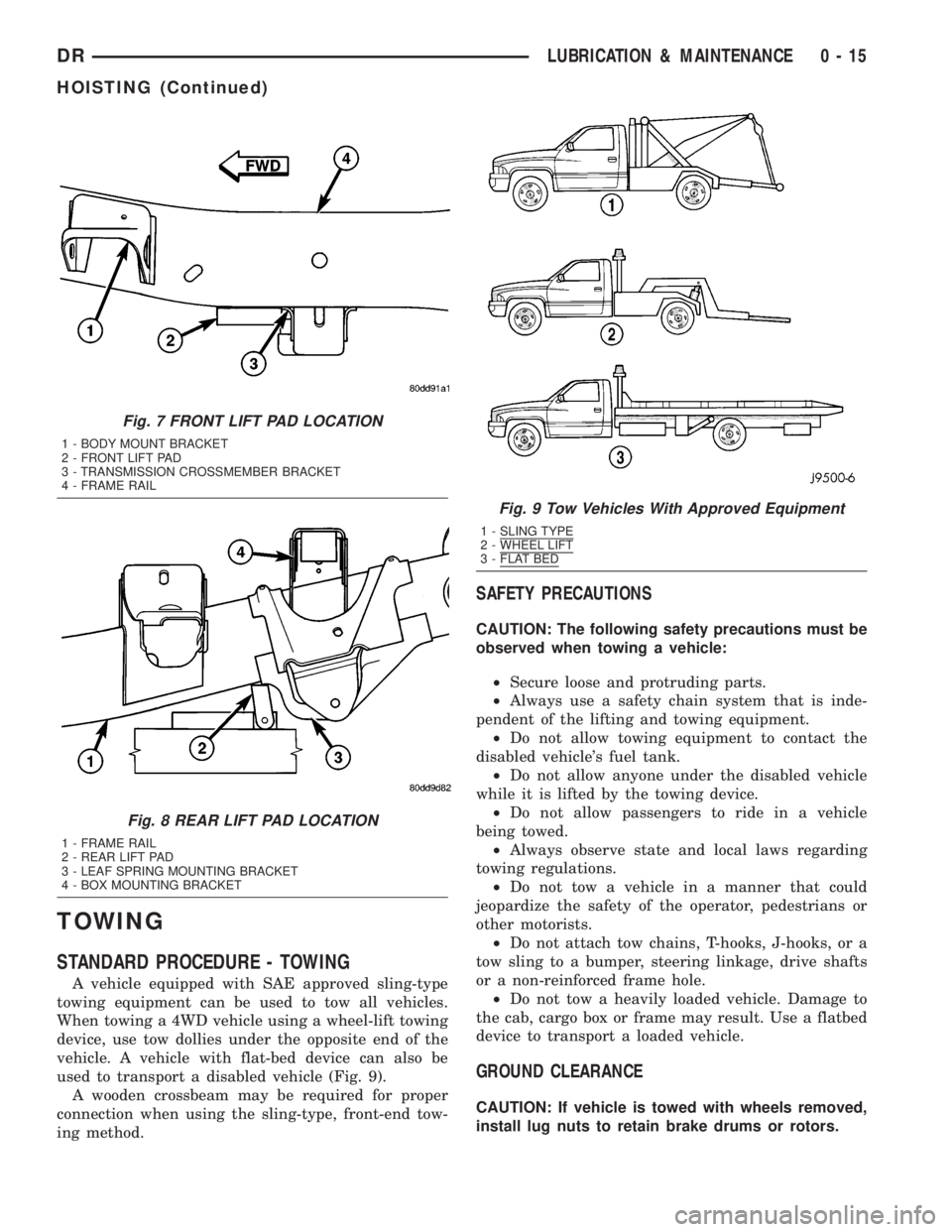
TOWING
STANDARD PROCEDURE - TOWING
A vehicle equipped with SAE approved sling-type
towing equipment can be used to tow all vehicles.
When towing a 4WD vehicle using a wheel-lift towing
device, use tow dollies under the opposite end of the
vehicle. A vehicle with flat-bed device can also be
used to transport a disabled vehicle (Fig. 9).
A wooden crossbeam may be required for proper
connection when using the sling-type, front-end tow-
ing method.
SAFETY PRECAUTIONS
CAUTION: The following safety precautions must be
observed when towing a vehicle:
²Secure loose and protruding parts.
²Always use a safety chain system that is inde-
pendent of the lifting and towing equipment.
²Do not allow towing equipment to contact the
disabled vehicle's fuel tank.
²Do not allow anyone under the disabled vehicle
while it is lifted by the towing device.
²Do not allow passengers to ride in a vehicle
being towed.
²Always observe state and local laws regarding
towing regulations.
²Do not tow a vehicle in a manner that could
jeopardize the safety of the operator, pedestrians or
other motorists.
²Do not attach tow chains, T-hooks, J-hooks, or a
tow sling to a bumper, steering linkage, drive shafts
or a non-reinforced frame hole.
²Do not tow a heavily loaded vehicle. Damage to
the cab, cargo box or frame may result. Use a flatbed
device to transport a loaded vehicle.
GROUND CLEARANCE
CAUTION: If vehicle is towed with wheels removed,
install lug nuts to retain brake drums or rotors.
Fig. 7 FRONT LIFT PAD LOCATION
1 - BODY MOUNT BRACKET
2 - FRONT LIFT PAD
3 - TRANSMISSION CROSSMEMBER BRACKET
4 - FRAME RAIL
Fig. 8 REAR LIFT PAD LOCATION
1 - FRAME RAIL
2 - REAR LIFT PAD
3 - LEAF SPRING MOUNTING BRACKET
4 - BOX MOUNTING BRACKET
Fig. 9 Tow Vehicles With Approved Equipment
1 - SLING TYPE2 - WHEEL LIFT3 - FLAT BED
DRLUBRICATION & MAINTENANCE 0 - 15
HOISTING (Continued)
Page 29 of 2895
A towed vehicle should be raised until lifted wheels
are a minimum 100 mm (4 in) from the ground. Be
sure there is adequate ground clearance at the oppo-
site end of the vehicle, especially when towing over
rough terrain or steep rises in the road. If necessary,
remove the wheels from the lifted end of the vehicle
and lower the vehicle closer to the ground, to
increase the ground clearance at the opposite end of
the vehicle. Install lug nuts on wheel attaching studs
to retain brake drums or rotors.
RAMP ANGLE
If a vehicle with flat-bed towing equipment is used,
the approach ramp angle should not exceed 15
degrees.
TOWING WHEN KEYS ARE NOT AVAILABLE
When the vehicle is locked and keys are not avail-
able, use a flat bed hauler. A Wheel-lift or Sling-type
device can be used on 4WD vehicles providedall the
wheels are lifted off the ground using tow dol-
lies.
FOUR-WHEEL-DRIVE VEHICLE TOWING
Chrysler Corporation recommends that a vehicle be
transported on a flat-bed device. A Wheel-lift or
Sling-type device can be used providedall the
wheels are lifted off the ground using tow dol-
lies.
WARNING: WHEN TOWING A DISABLED VEHICLE
AND THE DRIVE WHEELS ARE SECURED IN A
WHEEL LIFT OR TOW DOLLIES, ENSURE THE
TRANSMISSION IS IN THE PARK POSITION (AUTO-
MATIC TRANSMISSION) OR A FORWARD DRIVE
GEAR (MANUAL TRANSMISSION).
CAUTION: Many vehicles are equipped with air
dams, spoilers, and/or ground effect panels. To
avoid component damage, a wheel-lift towing vehi-
cle or a flat-bed hauling vehicle is recommended.
0 - 16 LUBRICATION & MAINTENANCEDR
TOWING (Continued)
Page 509 of 2895
WARNING: ON VEHICLES EQUIPPED WITH AIR-
BAGS, DISABLE THE SUPPLEMENTAL RESTRAINT
SYSTEM BEFORE ATTEMPTING ANY STEERING
WHEEL, STEERING COLUMN, DRIVER AIRBAG,
PASSENGER AIRBAG, SEAT BELT TENSIONER,
SIDE CURTAIN AIRBAG, OR INSTRUMENT PANEL
COMPONENT DIAGNOSIS OR SERVICE. DISCON-
NECT AND ISOLATE THE BATTERY NEGATIVE
(GROUND) CABLE, THEN WAIT TWO MINUTES FOR
THE SYSTEM CAPACITOR TO DISCHARGE BEFORE
PERFORMING FURTHER DIAGNOSIS OR SERVICE.
THIS IS THE ONLY SURE WAY TO DISABLE THE
SUPPLEMENTAL RESTRAINT SYSTEM. FAILURE TO
TAKE THE PROPER PRECAUTIONS COULD
RESULT IN ACCIDENTAL AIRBAG DEPLOYMENT
AND POSSIBLE PERSONAL INJURY.
CLUSTER BULB
This procedure applies to each of the incandescent
cluster illumination lamp bulb and bulb holder units.
If the vehicle is equipped with the optional Remote
Keyless Entry (RKE) system, and the RKE receiver
module was removed from the instrument cluster
rear cover to access the lower center cluster illumi-
nation lamp, reinstall the RKE module after the bulb
is replaced on the circuit board. (Refer to 8 - ELEC-
TRICAL/POWER LOCKS/REMOTE KEYLESS
ENTRY MODULE - INSTALLATION).
CAUTION: Always use the correct bulb size and
type for replacement. An incorrect bulb size or type
may overheat and cause damage to the instrument
cluster, the electronic circuit board and/or the
gauges.
(1) Insert the bulb and bulb holder unit straight
into the correct bulb mounting hole in the cluster
electronic circuit board (Fig. 6).
(2) With the bulb holder fully seated against the
cluster electronic circuit board, turn the bulb holder
clockwise about sixty degrees to lock it into place.
(3) Reinstall the instrument cluster onto the
instrument panel. (Refer to 8 - ELECTRICAL/IN-
STRUMENT CLUSTER - INSTALLATION).
(4) Reconnect the battery negative cable.CLUSTER LENS, HOOD, AND MASK
(1) Position the cluster lens, hood, and mask unit
over the face of the instrument cluster (Fig. 7). Be
certain that the odometer/trip odometer switch but-
ton is inserted through the proper clearance holes in
the mask and the lens.
(2) From the back of the instrument cluster, install
and tighten the eight screws around the outer perim-
eter of the rear cover that secure the lens, hood, and
mask unit to the cluster housing. Tighten the screws
to 1 N´m (10 in. lbs.).
(3) Reinstall the instrument cluster onto the
instrument panel. (Refer to 8 - ELECTRICAL/IN-
STRUMENT CLUSTER - INSTALLATION).
(4) Reconnect the battery negative cable.
INSTALLATION
WARNING: ON VEHICLES EQUIPPED WITH AIR-
BAGS, DISABLE THE SUPPLEMENTAL RESTRAINT
SYSTEM BEFORE ATTEMPTING ANY STEERING
WHEEL, STEERING COLUMN, DRIVER AIRBAG,
PASSENGER AIRBAG, SEAT BELT TENSIONER,
SIDE CURTAIN AIRBAG, OR INSTRUMENT PANEL
COMPONENT DIAGNOSIS OR SERVICE. DISCON-
NECT AND ISOLATE THE BATTERY NEGATIVE
(GROUND) CABLE, THEN WAIT TWO MINUTES FOR
THE SYSTEM CAPACITOR TO DISCHARGE BEFORE
PERFORMING FURTHER DIAGNOSIS OR SERVICE.
THIS IS THE ONLY SURE WAY TO DISABLE THE
SUPPLEMENTAL RESTRAINT SYSTEM. FAILURE TO
TAKE THE PROPER PRECAUTIONS COULD
RESULT IN ACCIDENTAL AIRBAG DEPLOYMENT
AND POSSIBLE PERSONAL INJURY.
(1) Position the instrument cluster to the instru-
ment panel.
(2) Reconnect the instrument panel wire harness
connectors for the cluster to the connector receptacles
on the back of the cluster housing.
(3) Position the instrument cluster into the instru-
ment panel.
(4) Install and tighten the four screws that secure
the instrument cluster to the instrument panel struc-
tural support (Fig. 5). Tighten the screws to 4 N´m
(31 in. lbs.).
(5) Reinstall the cluster bezel onto the instrument
panel. (Refer to 23 - BODY/INSTRUMENT PANEL/
CLUSTER BEZEL - INSTALLATION).
(6) Reconnect the battery negative cable.
8J - 16 INSTRUMENT CLUSTERDR
INSTRUMENT CLUSTER (Continued)
Page 548 of 2895
FOG LAMP
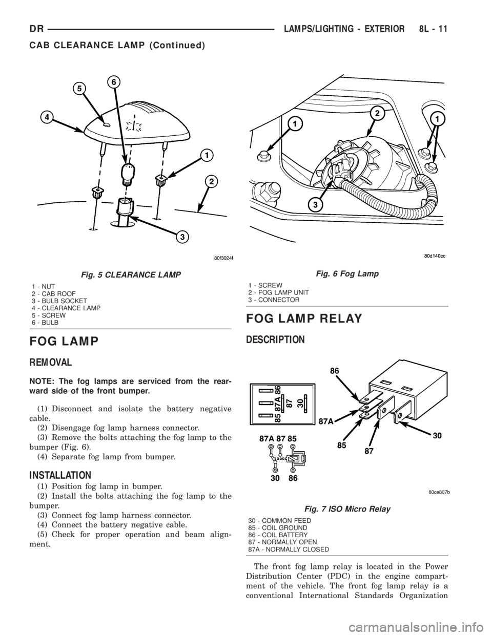
REMOVAL
NOTE: The fog lamps are serviced from the rear-
ward side of the front bumper.
(1) Disconnect and isolate the battery negative
cable.
(2) Disengage fog lamp harness connector.
(3) Remove the bolts attaching the fog lamp to the
bumper (Fig. 6).
(4) Separate fog lamp from bumper.
INSTALLATION
(1) Position fog lamp in bumper.
(2) Install the bolts attaching the fog lamp to the
bumper.
(3) Connect fog lamp harness connector.
(4) Connect the battery negative cable.
(5) Check for proper operation and beam align-
ment.
FOG LAMP RELAY
DESCRIPTION
The front fog lamp relay is located in the Power
Distribution Center (PDC) in the engine compart-
ment of the vehicle. The front fog lamp relay is a
conventional International Standards Organization
Fig. 5 CLEARANCE LAMP
1 - NUT
2 - CAB ROOF
3 - BULB SOCKET
4 - CLEARANCE LAMP
5 - SCREW
6 - BULB
Fig. 6 Fog Lamp
1 - SCREW
2 - FOG LAMP UNIT
3 - CONNECTOR
Fig. 7 ISO Micro Relay
30 - COMMON FEED
85 - COIL GROUND
86 - COIL BATTERY
87 - NORMALLY OPEN
87A - NORMALLY CLOSED
DRLAMPS/LIGHTING - EXTERIOR 8L - 11
CAB CLEARANCE LAMP (Continued)
Page 720 of 2895
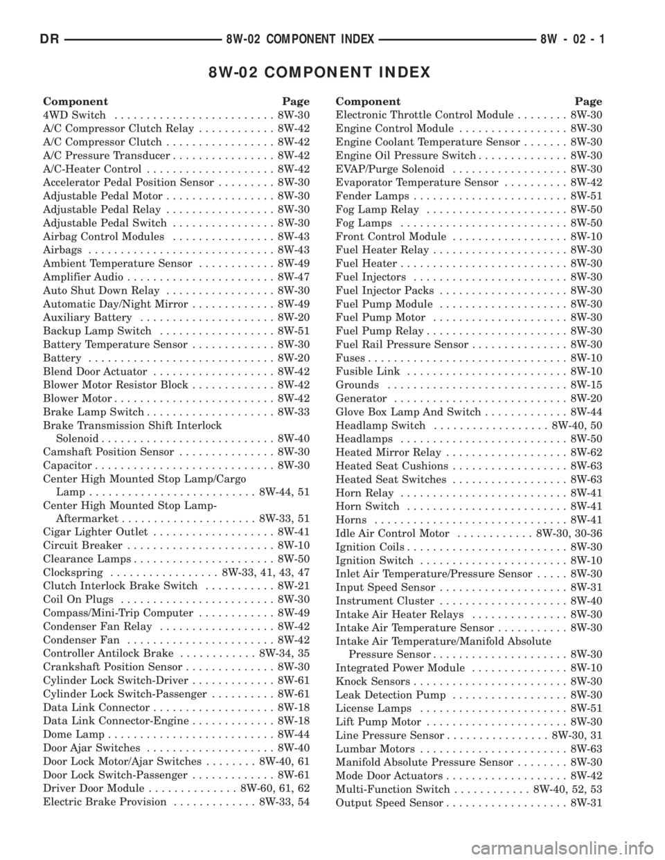
8W-02 COMPONENT INDEX
Component Page
4WD Switch......................... 8W-30
A/C Compressor Clutch Relay............ 8W-42
A/C Compressor Clutch................. 8W-42
A/C Pressure Transducer................ 8W-42
A/C-Heater Control.................... 8W-42
Accelerator Pedal Position Sensor......... 8W-30
Adjustable Pedal Motor................. 8W-30
Adjustable Pedal Relay................. 8W-30
Adjustable Pedal Switch................ 8W-30
Airbag Control Modules................ 8W-43
Airbags............................. 8W-43
Ambient Temperature Sensor............ 8W-49
Amplifier Audio....................... 8W-47
Auto Shut Down Relay................. 8W-30
Automatic Day/Night Mirror............. 8W-49
Auxiliary Battery..................... 8W-20
Backup Lamp Switch.................. 8W-51
Battery Temperature Sensor............. 8W-30
Battery............................. 8W-20
Blend Door Actuator................... 8W-42
Blower Motor Resistor Block............. 8W-42
Blower Motor......................... 8W-42
Brake Lamp Switch.................... 8W-33
Brake Transmission Shift Interlock
Solenoid........................... 8W-40
Camshaft Position Sensor............... 8W-30
Capacitor............................ 8W-30
Center High Mounted Stop Lamp/Cargo
Lamp.......................... 8W-44, 51
Center High Mounted Stop Lamp-
Aftermarket..................... 8W-33, 51
Cigar Lighter Outlet................... 8W-41
Circuit Breaker....................... 8W-10
Clearance Lamps...................... 8W-50
Clockspring................. 8W-33, 41, 43, 47
Clutch Interlock Brake Switch........... 8W-21
Coil On Plugs........................ 8W-30
Compass/Mini-Trip Computer............ 8W-49
Condenser Fan Relay.................. 8W-42
Condenser Fan....................... 8W-42
Controller Antilock Brake............ 8W-34, 35
Crankshaft Position Sensor.............. 8W-30
Cylinder Lock Switch-Driver............. 8W-61
Cylinder Lock Switch-Passenger.......... 8W-61
Data Link Connector................... 8W-18
Data Link Connector-Engine............. 8W-18
Dome Lamp.......................... 8W-44
Door Ajar Switches.................... 8W-40
Door Lock Motor/Ajar Switches........ 8W-40, 61
Door Lock Switch-Passenger............. 8W-61
Driver Door Module.............. 8W-60, 61, 62
Electric Brake Provision............. 8W-33, 54Component Page
Electronic Throttle Control Module........ 8W-30
Engine Control Module................. 8W-30
Engine Coolant Temperature Sensor....... 8W-30
Engine Oil Pressure Switch.............. 8W-30
EVAP/Purge Solenoid.................. 8W-30
Evaporator Temperature Sensor.......... 8W-42
Fender Lamps........................ 8W-51
Fog Lamp Relay...................... 8W-50
Fog Lamps.......................... 8W-50
Front Control Module.................. 8W-10
Fuel Heater Relay..................... 8W-30
Fuel Heater.......................... 8W-30
Fuel Injectors........................ 8W-30
Fuel Injector Packs.................... 8W-30
Fuel Pump Module.................... 8W-30
Fuel Pump Motor..................... 8W-30
Fuel Pump Relay...................... 8W-30
Fuel Rail Pressure Sensor............... 8W-30
Fuses............................... 8W-10
Fusible Link......................... 8W-10
Grounds............................ 8W-15
Generator........................... 8W-20
Glove Box Lamp And Switch............. 8W-44
Headlamp Switch.................. 8W-40, 50
Headlamps.......................... 8W-50
Heated Mirror Relay................... 8W-62
Heated Seat Cushions.................. 8W-63
Heated Seat Switches.................. 8W-63
Horn Relay.......................... 8W-41
Horn Switch......................... 8W-41
Horns.............................. 8W-41
Idle Air Control Motor............ 8W-30, 30-36
Ignition Coils......................... 8W-30
Ignition Switch....................... 8W-10
Inlet Air Temperature/Pressure Sensor..... 8W-30
Input Speed Sensor.................... 8W-31
Instrument Cluster.................... 8W-40
Intake Air Heater Relays............... 8W-30
Intake Air Temperature Sensor........... 8W-30
Intake Air Temperature/Manifold Absolute
Pressure Sensor..................... 8W-30
Integrated Power Module............... 8W-10
Knock Sensors........................ 8W-30
Leak Detection Pump.................. 8W-30
License Lamps....................... 8W-51
Lift Pump Motor...................... 8W-30
Line Pressure Sensor................ 8W-30, 31
Lumbar Motors....................... 8W-63
Manifold Absolute Pressure Sensor........ 8W-30
Mode Door Actuators................... 8W-42
Multi-Function Switch............ 8W-40, 52, 53
Output Speed Sensor................... 8W-31
DR8W-02 COMPONENT INDEX 8W - 02 - 1
Page 780 of 2895
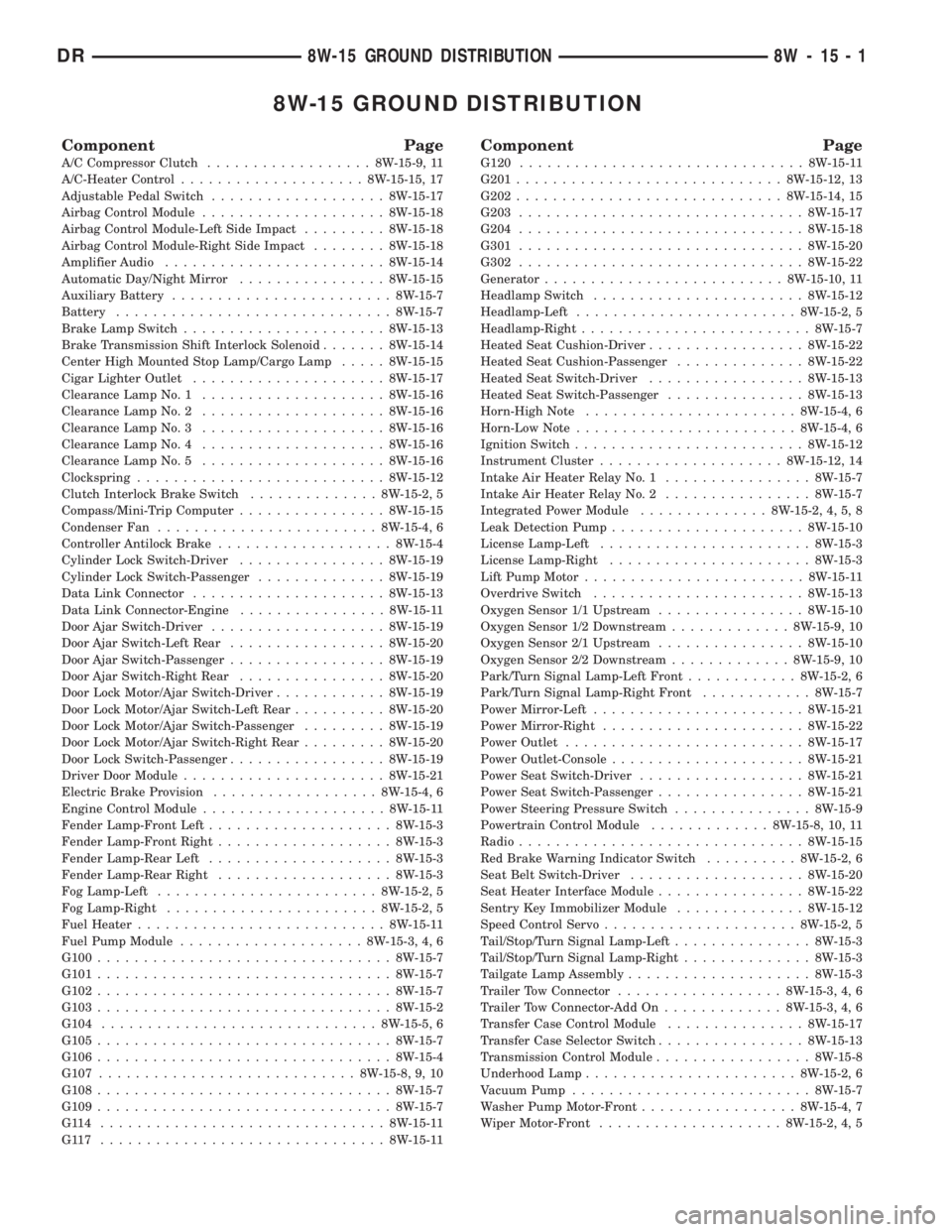
8W-15 GROUND DISTRIBUTION
Component Page
A/C Compressor Clutch..................8W-15-9, 11
A/C-Heater Control....................8W-15-15, 17
Adjustable Pedal Switch...................8W-15-17
Airbag Control Module....................8W-15-18
Airbag Control Module-Left Side Impact.........8W-15-18
Airbag Control Module-Right Side Impact........8W-15-18
Amplifier Audio........................8W-15-14
Automatic Day/Night Mirror................8W-15-15
Auxiliary Battery........................8W-15-7
Battery..............................8W-15-7
Brake Lamp Switch......................8W-15-13
Brake Transmission Shift Interlock Solenoid.......8W-15-14
Center High Mounted Stop Lamp/Cargo Lamp.....8W-15-15
Cigar Lighter Outlet.....................8W-15-17
Clearance Lamp No. 1....................8W-15-16
Clearance Lamp No. 2....................8W-15-16
Clearance Lamp No. 3....................8W-15-16
Clearance Lamp No. 4....................8W-15-16
Clearance Lamp No. 5....................8W-15-16
Clockspring...........................8W-15-12
Clutch Interlock Brake Switch..............8W-15-2, 5
Compass/Mini-Trip Computer................8W-15-15
Condenser Fan........................8W-15-4, 6
Controller Antilock Brake...................8W-15-4
Cylinder Lock Switch-Driver................8W-15-19
Cylinder Lock Switch-Passenger..............8W-15-19
Data Link Connector.....................8W-15-13
Data Link Connector-Engine................8W-15-11
Door Ajar Switch-Driver...................8W-15-19
Door Ajar Switch-Left Rear.................8W-15-20
Door Ajar Switch-Passenger.................8W-15-19
Door Ajar Switch-Right Rear................8W-15-20
Door Lock Motor/Ajar Switch-Driver............8W-15-19
Door Lock Motor/Ajar Switch-Left Rear..........8W-15-20
Door Lock Motor/Ajar Switch-Passenger.........8W-15-19
Door Lock Motor/Ajar Switch-Right Rear.........8W-15-20
Door Lock Switch-Passenger.................8W-15-19
Driver Door Module......................8W-15-21
Electric Brake Provision..................8W-15-4, 6
Engine Control Module....................8W-15-11
Fender Lamp-Front Left....................8W-15-3
Fender Lamp-Front Right...................8W-15-3
Fender Lamp-Rear Left....................8W-15-3
Fender Lamp-Rear Right...................8W-15-3
Fog Lamp-Left........................8W-15-2, 5
Fog Lamp-Right.......................8W-15-2, 5
Fuel Heater...........................8W-15-11
Fuel Pump Module....................8W-15-3, 4, 6
G100................................8W-15-7
G101................................8W-15-7
G102................................8W-15-7
G103................................8W-15-2
G104..............................8W-15-5, 6
G105................................8W-15-7
G106................................8W-15-4
G107............................8W-15-8, 9, 10
G108................................8W-15-7
G109................................8W-15-7
G114 ...............................8W-15-11
G117 ...............................8W-15-11
Component Page
G120...............................8W-15-11
G201.............................8W-15-12, 13
G202.............................8W-15-14, 15
G203...............................8W-15-17
G204...............................8W-15-18
G301...............................8W-15-20
G302...............................8W-15-22
Generator..........................8W-15-10, 11
Headlamp Switch.......................8W-15-12
Headlamp-Left........................8W-15-2, 5
Headlamp-Right.........................8W-15-7
Heated Seat Cushion-Driver.................8W-15-22
Heated Seat Cushion-Passenger..............8W-15-22
Heated Seat Switch-Driver.................8W-15-13
Heated Seat Switch-Passenger...............8W-15-13
Horn-High Note.......................8W-15-4, 6
Horn-Low Note........................8W-15-4, 6
Ignition Switch.........................8W-15-12
Instrument Cluster....................8W-15-12, 14
Intake Air Heater Relay No. 1................8W-15-7
Intake Air Heater Relay No. 2................8W-15-7
Integrated Power Module..............8W-15-2, 4, 5, 8
Leak Detection Pump.....................8W-15-10
License Lamp-Left.......................8W-15-3
License Lamp-Right......................8W-15-3
Lift Pump Motor........................8W-15-11
Overdrive Switch.......................8W-15-13
Oxygen Sensor 1/1 Upstream................8W-15-10
Oxygen Sensor 1/2 Downstream.............8W-15-9, 10
Oxygen Sensor 2/1 Upstream................8W-15-10
Oxygen Sensor 2/2 Downstream.............8W-15-9, 10
Park/Turn Signal Lamp-Left Front............8W-15-2, 6
Park/Turn Signal Lamp-Right Front............8W-15-7
Power Mirror-Left.......................8W-15-21
Power Mirror-Right......................8W-15-22
Power Outlet..........................8W-15-17
Power Outlet-Console.....................8W-15-21
Power Seat Switch-Driver..................8W-15-21
Power Seat Switch-Passenger................8W-15-21
Power Steering Pressure Switch...............8W-15-9
Powertrain Control Module.............8W-15-8, 10, 11
Radio...............................8W-15-15
Red Brake Warning Indicator Switch..........8W-15-2, 6
Seat Belt Switch-Driver...................8W-15-20
Seat Heater Interface Module................8W-15-22
Sentry Key Immobilizer Module..............8W-15-12
Speed Control Servo.....................8W-15-2, 5
Tail/Stop/Turn Signal Lamp-Left...............8W-15-3
Tail/Stop/Turn Signal Lamp-Right..............8W-15-3
Tailgate Lamp Assembly....................8W-15-3
Trailer Tow Connector..................8W-15-3, 4, 6
Trailer Tow Connector-Add On.............8W-15-3, 4, 6
Transfer Case Control Module...............8W-15-17
Transfer Case Selector Switch................8W-15-13
Transmission Control Module.................8W-15-8
Underhood Lamp.......................8W-15-2, 6
Vacuum Pump..........................8W-15-7
Washer Pump Motor-Front.................8W-15-4, 7
Wiper Motor-Front....................8W-15-2, 4, 5
DR8W-15 GROUND DISTRIBUTION 8W - 15 - 1
Page 1110 of 2895
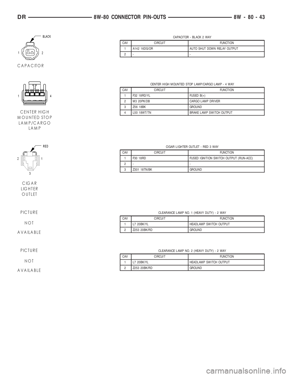
CAPACITOR - BLACK 2 WAY
CAV CIRCUIT FUNCTION
1 A142 16DG/OR AUTO SHUT DOWN RELAY OUTPUT
2- -
CENTER HIGH MOUNTED STOP LAMP/CARGO LAMP-4WAY
CAV CIRCUIT FUNCTION
1 F32 18RD/YL FUSED B(+)
2 M3 20PK/DB CARGO LAMP DRIVER
3 Z56 18BK GROUND
4 L50 18WT/TN BRAKE LAMP SWITCH OUTPUT
CIGAR LIGHTER OUTLET - RED 3 WAY
CAV CIRCUIT FUNCTION
1 F30 18RD FUSED IGNITION SWITCH OUTPUT (RUN-ACC)
2- -
3 Z301 18TN/BK GROUND
CLEARANCE LAMP NO. 1 (HEAVY DUTY)-2WAY
CAV CIRCUIT FUNCTION
1 L7 20BK/YL HEADLAMP SWITCH OUTPUT
2 Z253 20BK/RD GROUND
CLEARANCE LAMP NO. 2 (HEAVY DUTY)-2WAY
CAV CIRCUIT FUNCTION
1 L7 20BK/YL HEADLAMP SWITCH OUTPUT
2 Z253 20BK/RD GROUND
DR8W-80 CONNECTOR PIN-OUTS 8W - 80 - 43
Page 1111 of 2895
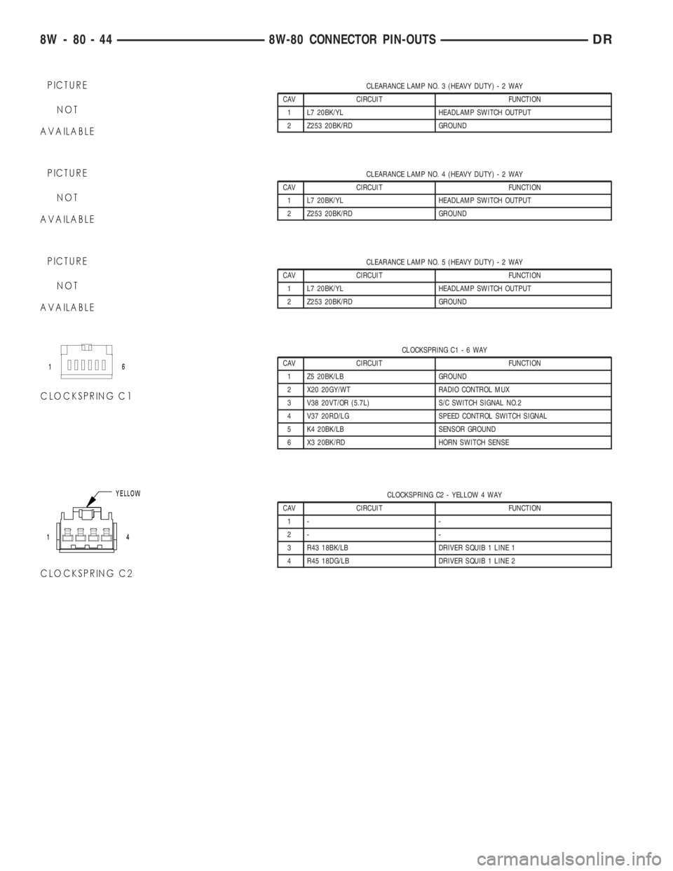
CLEARANCE LAMP NO. 3 (HEAVY DUTY)-2WAY
CAV CIRCUIT FUNCTION
1 L7 20BK/YL HEADLAMP SWITCH OUTPUT
2 Z253 20BK/RD GROUND
CLEARANCE LAMP NO. 4 (HEAVY DUTY)-2WAY
CAV CIRCUIT FUNCTION
1 L7 20BK/YL HEADLAMP SWITCH OUTPUT
2 Z253 20BK/RD GROUND
CLEARANCE LAMP NO. 5 (HEAVY DUTY)-2WAY
CAV CIRCUIT FUNCTION
1 L7 20BK/YL HEADLAMP SWITCH OUTPUT
2 Z253 20BK/RD GROUND
CLOCKSPRING C1-6WAY
CAV CIRCUIT FUNCTION
1 Z5 20BK/LB GROUND
2 X20 20GY/WT RADIO CONTROL MUX
3 V38 20VT/OR (5.7L) S/C SWITCH SIGNAL NO.2
4 V37 20RD/LG SPEED CONTROL SWITCH SIGNAL
5 K4 20BK/LB SENSOR GROUND
6 X3 20BK/RD HORN SWITCH SENSE
CLOCKSPRING C2 - YELLOW 4 WAY
CAV CIRCUIT FUNCTION
1- -
2- -
3 R43 18BK/LB DRIVER SQUIB 1 LINE 1
4 R45 18DG/LB DRIVER SQUIB 1 LINE 2
8W - 80 - 44 8W-80 CONNECTOR PIN-OUTSDR
Page 1180 of 2895
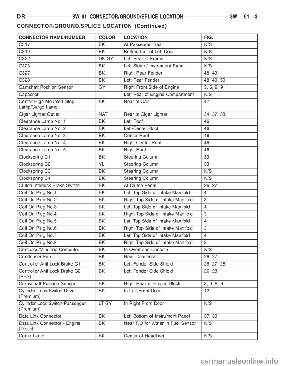
CONNECTOR NAME/NUMBER COLOR LOCATION FIG.
C317 BK At Passenger Seat N/S
C319 BK Bottom Left of Left Door N/S
C322 DK GY Left Rear of Frame N/S
C323 BK Left Side of Instrument Panel N/S
C327 BK Right Rear Fender 48, 49
C328 BK Left Rear Fender 48, 49, 50
Camshaft Position Sensor GY Right Front Side of Engine 3, 6, 8, 9
Capacitor Left Rear of Engine Compartment N/S
Center High Mounted Stop
Lamp/Cargo LampBK Rear of Cab 47
Cigar Lighter Outlet NAT Rear of Cigar Lighter 34, 37, 38
Clearance Lamp No. 1 BK Left Roof 46
Clearance Lamp No. 2 BK Left-Center Roof 46
Clearance Lamp No. 3 BK Center Roof 46
Clearance Lamp No. 4 BK Right-Center Roof 46
Clearance Lamp No. 5 BK Right Roof 46
Clockspring C1 BK Steering Column 33
Clockspring C2 YL Steering Column 33
Clockspring C3 BK Steering Column N/S
Clockspring C4 BK Steering Column N/S
Clutch Interlock Brake Switch BK At Clutch Pedal 26, 27
Coil On Plug No.1 BK Left Top Side of Intake Manifold 4
Coil On Plug No.2 BK Right Top Side of Intake Manifold 3
Coil On Plug No.3 BK Left Top Side of Intake Manifold 4
Coil On Plug No.4 BK Right Top Side of Intake Manifold 3
Coil On Plug No.5 BK Left Top Side of Intake Manifold 4
Coil On Plug No.6 BK Right Top Side of Intake Manifold 3
Coil On Plug No.7 BK Left Top Side of Intake Manifold 4
Coil On Plug No.8 BK Right Top Side of Intake Manifold 3
Compass/Mini-Trip Computer BK In Overhead Console N/S
Condenser Fan BK Near Condenser 26, 27
Controller Anti-Lock Brake C1 BK Left Fender Side Shield 26, 27, 28
Controller Anti-Lock Brake C2
(ABS)BK Left Fender Side Shield 26, 28
Crankshaft Position Sensor BK Right Rear of Engine Block 3, 6, 8, 9
Cylinder Lock Switch-Driver
(Premium)BK In Left Front Door 42
Cylinder Lock Switch-Passenger
(Premium)LT GY In Right Front Door N/S
Data Link Connector BK Left Bottom of Instrument Panel 37, 39
Data Link Connector - Engine
(Diesel)BK Near T/O for Water In Fuel Sensor N/S
Dome Lamp BK Center of Headliner N/S
DR8W-91 CONNECTOR/GROUND/SPLICE LOCATION 8W - 91 - 3
CONNECTOR/GROUND/SPLICE LOCATION (Continued)
Page 1261 of 2895
(17) Connect the engine to body ground straps at
the left side of the cowl.
(18) Install the intake manifold.
(19) Install the engine oil dipstick tube.
(20) Install the power brake booster vacuum hose.
(21) Install the breather hoses.
(22) Install the PCV hose.
(23) Install the fuel rail.
(24) Install the coil over plugs.
(25) Connect the engine wiring harness at the fol-
lowing points:
²Intake air temperature (IAT) sensor
²Fuel Injectors
²Throttle Position (TPS) Switch
²Idle Air Control (IAC) Motor
²Engine Oil Pressure Switch
²Engine Coolant Temperature (ECT) Sensor
²Manifold Absolute Pressure MAP) Sensor
²Camshaft Position (CMP) Sensor
²Coil Over Plugs
²Crankshaft Position Sensor
(26) Reinstall the radiator/cooling module assem-
bly.
(27) Connect lower radiator hose.
(28) Connect upper radiator hose.
(29) Connect throttle and speed control cables.
(30) Install the heater hose assembly.
(31) Install coolant recovery bottle.
(32) Install the power steering pump.
(33) Install the generator.
(34) Install the A/C compressor.
(35) Install the drive belt.
(36) Install the fan shroud with the viscous fan
assembly.
(37) Install the radiator core support bracket.
(38) Install the air cleaner assembly.
(39) Refill the engine cooling system.
(40) Recharge the air conditioning.
(41) Install the hood.
(42) Check and fill engine oil.
(43) Connect the battery negative cable.
(44) Start the engine and check for leaks.SPECIFICATIONS
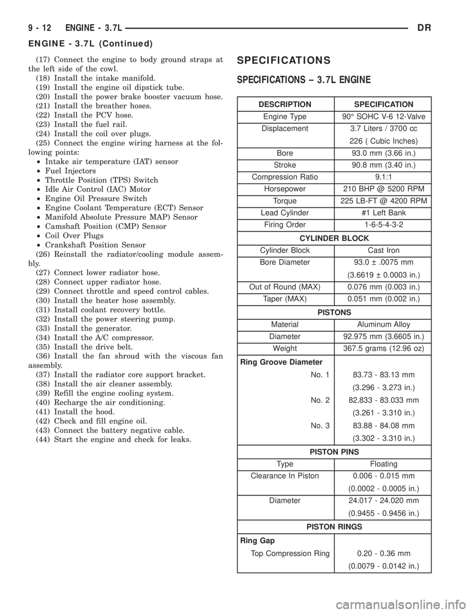
SPECIFICATIONS ± 3.7L ENGINE
DESCRIPTION SPECIFICATION
Engine Type 90É SOHC V-6 12-Valve
Displacement 3.7 Liters / 3700 cc
226 ( Cubic Inches)
Bore 93.0 mm (3.66 in.)
Stroke 90.8 mm (3.40 in.)
Compression Ratio 9.1:1
Horsepower 210 BHP @ 5200 RPM
Torque 225 LB-FT @ 4200 RPM
Lead Cylinder #1 Left Bank
Firing Order 1-6-5-4-3-2
CYLINDER BLOCK
Cylinder Block Cast Iron
Bore Diameter 93.0 .0075 mm
(3.6619 0.0003 in.)
Out of Round (MAX) 0.076 mm (0.003 in.)
Taper (MAX) 0.051 mm (0.002 in.)
PISTONS
Material Aluminum Alloy
Diameter 92.975 mm (3.6605 in.)
Weight 367.5 grams (12.96 oz)
Ring Groove Diameter
No. 1 83.73 - 83.13 mm
(3.296 - 3.273 in.)
No. 2 82.833 - 83.033 mm
(3.261 - 3.310 in.)
No. 3 83.88 - 84.08 mm
(3.302 - 3.310 in.)
PISTON PINS
Type Floating
Clearance In Piston 0.006 - 0.015 mm
(0.0002 - 0.0005 in.)
Diameter 24.017 - 24.020 mm
(0.9455 - 0.9456 in.)
PISTON RINGS
Ring Gap
Top Compression Ring 0.20 - 0.36 mm
(0.0079 - 0.0142 in.)
9 - 12 ENGINE - 3.7LDR
ENGINE - 3.7L (Continued)