jump cable DODGE RAM 2003 Service Repair Manual
[x] Cancel search | Manufacturer: DODGE, Model Year: 2003, Model line: RAM, Model: DODGE RAM 2003Pages: 2895, PDF Size: 83.15 MB
Page 26 of 2895
JUMP STARTING
STANDARD PROCEDURE - JUMP STARTING
WARNING: REVIEW ALL SAFETY PRECAUTIONS
AND WARNINGS IN THE BATTERY SYSTEM SEC-
TION OF THE SERVICE MANUAL. (Refer to 8 -
ELECTRICAL/BATTERY SYSTEM/BATTERY - STAN-
DARD PROCEDURE)
²DO NOT JUMP START A FROZEN BATTERY,
PERSONAL INJURY CAN RESULT.
²IF EQUIPPED, DO NOT JUMP START WHEN
MAINTENANCE FREE BATTERY INDICATOR DOT IS
YELLOW OR BRIGHT COLOR.
²DO NOT JUMP START A VEHICLE WHEN THE
BATTERY FLUID IS BELOW THE TOP OF LEAD
PLATES.
²DO NOT ALLOW JUMPER CABLE CLAMPS TO
TOUCH EACH OTHER WHEN CONNECTED TO A
BOOSTER SOURCE.
²DO NOT USE OPEN FLAME NEAR BATTERY.
²REMOVE METALLIC JEWELRY WORN ON
HANDS OR WRISTS TO AVOID INJURY BY ACCI-
DENTAL ARCING OF BATTERY CURRENT.
²WHEN USING A HIGH OUTPUT BOOSTING
DEVICE, DO NOT ALLOW BATTERY VOLTAGE TO
EXCEED 16 VOLTS. REFER TO INSTRUCTIONS
PROVIDED WITH DEVICE BEING USED.
FAILURE TO FOLLOW THESE INSTRUCTIONS MAY
RESULT IN PERSONAL INJURY.
CAUTION: When using another vehicle as a
booster, do not allow vehicles to touch. Electrical
systems can be damaged on either vehicle.
TO JUMP START A DISABLED VEHICLE:
(1) Raise hood on disabled vehicle and visually
inspect engine compartment for:
²Battery cable clamp condition, clean if necessary.
²Frozen battery.
²Yellow or bright color test indicator, if equipped.
²Low battery fluid level.
²Generator drive belt condition and tension.
²Fuel fumes or leakage, correct if necessary.CAUTION: If the cause of starting problem on dis-
abled vehicle is severe, damage to booster vehicle
charging system can result.
(2) When using another vehicle as a booster
source, park the booster vehicle within cable reach.
Turn off all accessories, set the parking brake, place
the automatic transmission in PARK or the manual
transmission in NEUTRAL and turn the ignition
OFF.
(3) On disabled vehicle, place gear selector in park
or neutral and set park brake. Turn off all accesso-
ries.
(4) Connect jumper cables to booster battery. RED
clamp to positive terminal (+). BLACK clamp to neg-
ative terminal (-). DO NOT allow clamps at opposite
end of cables to touch, electrical arc will result.
Review all warnings in this procedure.
(5) On disabled vehicle, connect RED jumper cable
clamp to positive (+) terminal. Connect BLACK
jumper cable clamp to engine ground as close to the
ground cable attaching point as possible.
(6) Start the engine in the vehicle which has the
booster battery, let the engine idle a few minutes,
then start the engine in the vehicle with the dis-
charged battery.
CAUTION: Do not crank starter motor on disabled
vehicle for more than 15 seconds, starter will over-
heat and could fail.
(7) Allow battery in disabled vehicle to charge to
at least 12.4 volts (75% charge) before attempting to
start engine. If engine does not start within 15 sec-
onds, stop cranking engine and allow starter to cool
(15 min.), before cranking again.
DISCONNECT CABLE CLAMPS AS FOLLOWS:
²Disconnect BLACK cable clamp from engine
ground on disabled vehicle.
²When using a Booster vehicle, disconnect
BLACK cable clamp from battery negative terminal.
Disconnect RED cable clamp from battery positive
terminal.
²Disconnect RED cable clamp from battery posi-
tive terminal on disabled vehicle.
DRLUBRICATION & MAINTENANCE 0 - 13
Page 418 of 2895
WARNING: ALWAYS WEAR APPROPRIATE EYE
PROTECTION AND USE EXTREME CAUTION WHEN
WORKING WITH BATTERIES.
BATTERY TESTING
(1) If testing the battery OUT-OF-VEHICLE, clean
the battery terminals with a wire brush before test-
ing. If the battery is equipped with side post termi-
nals, install and tighten the supplied lead terminal
stud adapters. Do not use steel bolts. Failure to prop-
erly install the stud adapters, or using stud adapters
that are dirty or worn-out may result in false test
readings.
(2) If testing the battery IN-THE-VEHICLE, make
certain all of the vehicle accessory loads are OFF,
including the ignition.The preferred test position
is at the battery terminal. If the battery is not
accessible, you may test using both the positive and
negative jumper posts. Select TESTING AT JUMPER
POST when connecting to that location.
(3) Connect the tester (Fig. 9) to the battery or
jumper posts, the red clamp to positive (+) and the
black clamp to negative (±).
NOTE: Multiple batteries connected in parallel must
have the ground cable disconnected to perform a
battery test. Failure to disconnect may result in
false battery test readings.
(4) Using the ARROW key selectinoroutof vehi-
cle testing and press ENTER to make a selection.
(5) If not selected, choose the Cold Cranking Amp
(CCA) battery rating. Or select the appropriate bat-
tery rating for your area (see menu). The tester will
then run its self programmed test of the battery and
display the results. Refer to the test result table
noted below.
CAUTION: If REPLACE BATTERY is the result of the
test, this may mean a poor connection between the
vehicle's cables and battery exists. After discon-
necting the vehicle's battery cables from the bat-
tery, retest the battery using the OUT-OF-VEHICLE
test before replacing.
(6) While viewing the battery test result, press the
CODE button and the tester will prompt you for the
last 4 digits of the VIN. Use the UP/DOWN arrow
buttons to scroll to the correct character; then press
ENTER to select and move to the next digit. Then
press the ENTER button to view the SERVICE
CODE. Pressing the CODE button a second time will
return you to the test results.
BATTERY TEST RESULTS
GOOD BATTERY Return to service
GOOD - RECHARGE Fully charge battery and
return to service
CHARGE & RETEST Fully charge battery and
retest battery
REPLACE BATTERY Replace the battery and
retest complete system
BAD-CELL REPLACE Replace the battery and
retest complete system
NOTE: The SERVICE CODE is required on every
warranty claim submitted for battery replacement.
REMOVAL
(1) Turn the ignition switch to the Off position. Be
certain that all electrical accessories are turned off.
(2) Loosen the battery negative cable terminal
clamp pinch-bolt hex nut.
(3) Disconnect the battery negative cable terminal
clamp from the battery negative terminal post. If
necessary, use a battery terminal puller to remove
the terminal clamp from the battery post (Fig. 10).
(4) Loosen the battery positive cable terminal
clamp pinch-bolt hex nut.
(5) Disconnect the battery positive cable terminal
clamp from the battery positive terminal post. If nec-
essary, use a battery terminal puller to remove the
terminal clamp from the battery post (Fig. 10).
(6) Remove the battery hold down retaining bolt.
WARNING: WEAR A SUITABLE PAIR OF RUBBER
GLOVES (NOT THE HOUSEHOLD TYPE) WHEN
REMOVING A BATTERY BY HAND. SAFETY
GLASSES SHOULD ALSO BE WORN. IF THE BAT-
TERY IS CRACKED OR LEAKING, THE ELECTRO-
LYTE CAN BURN THE SKIN AND EYES.
Fig. 10 Removing Battery Cable Terminal Clamp
1 - BATTERY
2 - BATTERY TERMINAL PULLER
DRBATTERY SYSTEM 8F - 13
BATTERY (Continued)
Page 439 of 2895
SPECIFICATIONS - TORQUE - STARTING
SYSTEM
DESCRIPTION N´m Ft. Lbs. In. Lbs.
Battery Cable Eyelet Nut at
Solenoid (large nut - gas engines)25 19 221
Battery Cable Eyelet Nut at
Solenoid (large nut - diesel engine)14 - 120
Starter Solenoid Nut (small nut -
diesel engine)6-55
Starter Mounting Bolts - Gas
Engines68 50 -
Starter Mounting Nut - Gas Engines 68 50 -
Starter Mounting Bolts - Diesel 43 32 -
STARTER MOTOR
DIAGNOSIS AND TESTING - STARTER MOTOR
Correct starter motor operation can be confirmed
by performing the following free running bench test.
This test can only be performed with starter motor
removed from vehicle. Refer to Specifications for
starter motor specifications.
(1) Remove starter motor from vehicle. Refer to
Starter Motor Removal and Installation.
(2) Mount starter motor securely in a soft-jawed
bench vise. The vise jaws should be clamped on the
mounting flange of starter motor. Never clamp on
starter motor by field frame.
(3) Connect a suitable volt-ampere tester and a
12-volt battery to starter motor in series, and set
ammeter to 100 ampere scale. See instructions pro-
vided by manufacturer of volt-ampere tester being
used.
(4) Install jumper wire from solenoid terminal to
solenoid battery terminal. The starter motor should
operate. If starter motor fails to operate, replace
faulty starter motor assembly.
(5) Adjust carbon pile load of tester to obtain free
running test voltage. Refer to Specifications for
starter motor free running test voltage specifications.
(6) Note reading on ammeter and compare reading
to free running test maximum amperage draw. Refer
to Specifications for starter motor free running test
maximum amperage draw specifications.
(7) If ammeter reading exceeds maximum amper-
age draw specification, replace faulty starter motor
assembly.
STARTER SOLENOID
This test can only be performed with starter motor
removed from vehicle.(1) Remove starter motor from vehicle. Refer to
Starter Motor Removal and Installation.
(2) Disconnect wire from solenoid field coil termi-
nal.
(3) Check for continuity between solenoid terminal
and solenoid field coil terminal with a continuity
tester (Fig. 7). There should be continuity. If OK, go
to Step 4. If not OK, replace faulty starter motor
assembly.
(4) Check for continuity between solenoid terminal
and solenoid case (Fig. 8). There should be continuity.
If not OK, replace faulty starter motor assembly.
REMOVAL
3.7L / 4.7L
(1) Disconnect and isolate negative battery cable.
(2) Raise and support vehicle.
(3) Note: If equipped with 4WD and certain trans-
missions, a support bracket is used between front
axle and side of transmission. Remove 2 support
bracket bolts at transmission. Pry support bracket
slightly to gain access to lower starter mounting bolt.
Fig. 7 CONTINUITY BETWEEN SOLENOID AND
FIELD COIL TERMINALS - TYPICAL
1 - OHMMETER
2 - SOLENOID TERMINAL
3 - FIELD COIL TERMINAL
8F - 34 STARTINGDR
STARTING (Continued)
Page 491 of 2895
CAUTION: Do not leave any one spark plug cable
disconnected for longer than necessary during test-
ing. This may cause possible heat damage to the
catalytic converter. Total test time must not exceed
ten minutes.
Except 5.7L V-8 :With the engine running,
remove spark plug cable from spark plug (one at a
time) and hold next to a good engine ground. If the
cable and spark plug are in good condition, the
engine rpm should drop and the engine will run
poorly. If engine rpm does not drop, the cable and/or
spark plug may not be operating properly and should
be replaced. Also check engine cylinder compression.
With the engine not running, connect one end of a
test probe to a good ground. Start the engine and run
the other end of the test probe along the entire
length of all spark plug cables. If cables are cracked
or punctured, there will be a noticeable spark jump
from the damaged area to the test probe. The cable
running from the ignition coil to the distributor cap
can be checked in the same manner. Cracked, dam-
aged or faulty cables should be replaced with resis-
tance type cable. This can be identified by the words
ELECTRONIC SUPPRESSION printed on the cable
jacket.Use an ohmmeter to test for open circuits, exces-
sive resistance or loose terminals. If equipped,
remove the distributor cap from the distributor.Do
not remove cables from cap.Remove cable from
spark plug. Connect ohmmeter to spark plug termi-
nal end of cable and to corresponding electrode in
distributor cap. Resistance should be 250 to 1000
Ohms per inch of cable. If not, remove cable from dis-
tributor cap tower and connect ohmmeter to the ter-
minal ends of cable. If resistance is not within
specifications as found in the SPARK PLUG CABLE
RESISTANCE chart, replace the cable. Test all spark
plug cables in this manner.
SPARK PLUG CABLE RESISTANCE
MINIMUM MAXIMUM
250 Ohms Per Inch 1000 Ohms Per Inch
3000 Ohms Per Foot 12,000 Ohms Per Foot
To test ignition coil-to-distributor cap cable (if
applicaple), do not remove the cable from the cap.
Connect ohmmeter to rotor button (center contact) of
distributor cap and terminal at ignition coil end of
cable. If resistance is not within specifications as
found in the Spark Plug Cable Resistance chart,
remove the cable from the distributor cap. Connect
the ohmmeter to the terminal ends of the cable. If
resistance is not within specifications as found in the
Spark Plug Cable Resistance chart, replace the cable.
Inspect the ignition coil tower for cracks, burns or
corrosion.
REMOVAL
5.9L V-8 / 8.0L V-10
CAUTION: When disconnecting a high voltage cable
from a spark plug or from the distributor cap, twist
the rubber boot slightly (1/2 turn) to break it loose
(Fig. 54). Grasp the boot (not the cable) and pull it
off with a steady, even force.
On 5.9L V-8 engines, spark plug cable heat shields
are pressed into the cylinder head to surround each
spark plug cable boot and spark plug (Fig. 53). These
shields protect the spark plug boots from damage
(due to intense engine heat generated by the exhaust
manifolds) and should not be removed. After the
spark plug cable has been installed, the lip of the
cable boot should have a small air gap to the top of
the heat shield (Fig. 53).
Fig. 53 HEAT SHIELDS - 5.9L V-8
1 - AIR GAP
2 - SPARK PLUG BOOT HEAT SHIELD
8I - 34 IGNITION CONTROLDR
SPARK PLUG CABLE (Continued)
Page 574 of 2895
then sends the proper ambient temperature mes-
sages to the EVIC, CMTC over the PCI J1850 data
bus.
The temperature function is supported by the
ambient temperature sensor, a wiring circuit, the
Front Control Module, the Programmable Communi-
cations Interface (PCI) data bus, and a portion of the
Electronics module. If any portion of the ambient
temperature sensor circuit fails, the Front Control
Module will self-diagnose the circuit.
For complete circuit diagrams, refer toWiring.
DIAGNOSIS AND TESTING
DIAGNOSIS AND TESTING - AMBIENT
TEMPERATURE SENSOR
(1) Turn the ignition switch to the Off position.
Disconnect and isolate the battery negative cable.
Disconnect the ambient temperature sensor wire har-
ness connector.
(2) Measure the resistance of the ambient temper-
ature sensor. At 24É C (75É F), the sensor resistance
should be approximately 10.3 kilohms. At 30É C (86É
F), the sensor resistance should be approximately
7.57 kilohms. The sensor resistance should decrease
as the temperature rises. If OK, refer toDiagnosis
and Testing - Ambient Temperature Sensor Cir-
cuitin this group. If not OK, replace the faulty
ambient temperature sensor.
NOTE: The ambient temperature sensor is a very
sensitive device. When testing, be certain the tem-
perature sensor has had time to stabilize (room
temperature) before attempting to read the sensor
resistance. Failure to let the ambient temperature
sensor temperature stabilize could result in a mis-
leading test.
DIAGNOSIS AND TESTING - AMBIENT
TEMPERATURE SENSOR CIRCUIT
(1) Turn the ignition switch to the Off position.
Disconnect and isolate the battery negative cable.
Disconnect the ambient temperature sensor wire har-
ness connector and the Front Control Module wire
harness connector.
(2) Connect a jumper wire between the two termi-
nals of the ambient temperature sensor wire harness
connector.
(3) Check for continuity between the sensor return
circuit and the ambient temperature sensor signal
circuit cavities of the Front Control Module wire har-
ness connector. There should be continuity. If OK, go
to Step 4. If not OK, repair the open sensor return or
signal circuit as required.(4) Remove the jumper wire from the ambient tem-
perature sensor wire harness connector. Check for
continuity between the sensor return circuit cavity of
the Front Control Module wire harness connector
and a good ground. There should be no continuity. If
OK, go to Step 5. If not OK, repair the shorted sen-
sor return circuit as required.
(5) Check for continuity between the ambient tem-
perature sensor signal circuit cavity of the Front
Control Module wire harness connector and a good
ground. There should be no continuity. If OK, refer to
Diagnosis and Testing - Overhead Consolein
this group. If not OK, repair the shorted ambient
temperature sensor signal circuit as required.
REMOVAL
(1) Open the hood.
(2) Disconnect and isolate the battery negative
cable.
(3) Working on the underside of the hood, remove
screw holding sensor to hood panel.
(4) Disconnect the sensor electrical connector and
remove sensor from vehicle.
INSTALLATION
(1) Connect the sensor electrical connector.
(2) Working on the underside of the hood, install
screw holding sensor to hood panel.
(3) Connect the battery negative cable.
(4) Close the hood.
UNIVERSAL TRANSMITTER
DESCRIPTION
Some DR models are equipped with a universal
transmitter transceiver. The universal transmitter is
integral to the Electronic Vehicle Information Center
(EVIC) and the Compass Mini-Trip Computer
(CMTC), which is located in the overhead console.
The only visible component of the universal transmit-
ter are the three transmitter push buttons centered
between the modules push buttons located just rear-
ward of the display screen in the overhead console.
The three universal transmitter push buttons are
identified with one, two or three light indicators so
that they be easily identified.
Each of the three universal transmitter push but-
tons control an independent radio transmitter chan-
nel. Each of these three channels can be trained to
transmit a different radio frequency signal for the
remote operation of garage door openers, motorized
gate openers, home or office lighting, security sys-
tems or just about any other device that can be
equipped with a radio receiver in the 286 to 399
MegaHertz (MHz) frequency range for remote opera-
DRMESSAGE SYSTEMS 8M - 11
AMBIENT TEMP SENSOR (Continued)
Page 599 of 2895
(Refer to 23 - BODY/DOOR - FRONT/TRIM PANEL -
REMOVAL).
(2) Disconnect power window motor wire connector
from door harness.
(3) Using two jumper wires, connect one to a bat-
tery (+) source and the other to a good ground (-).
(4) Connect the Negative (-) jumper probe to one of
the motor connector terminals.
(5) Momentarily touch the Positive (+) jumper
probe to the other motor connector terminal.
When positive probe is connected the motor should
rotate in one direction to either move window up or
down. If window is all the way up or down the motor
will grunt and the inner door panel will flex when
actuated in that one direction.
(6) Reverse jumper probes at the motor connector
terminals and window should now move in opposite
direction. If window does not move or grunt, replace
the motor.
If window moved completely up or down, reverse
the jumper probes and cycle window to the opposite
position to verify full operation.
If motor grunts and does not move, verify that reg-
ulator is not binding.
WINDOW MOTOR
REMOVAL
The window motor is serviced with the window reg-
ulator (Refer to 23 - BODY/DOOR - FRONT/WINDOW
REGULATOR - REMOVAL) or (Refer to 23 - BODY/
DOORS - REAR/WINDOW REGULATOR - REMOVAL).
WINDOW SWITCH
DIAGNOSIS AND TESTING - WINDOW SWITCH
The Light-Emitting Diode (LED) illumination
lamps for all of the power window and lock switch
and bezel unit switch paddles receive battery current
through the power window circuit breaker in the
junction block. If all of the LEDs are inoperative in
both the power window and lock switch units and the
power windows are inoperative, (Refer to 8 - ELEC-
TRICAL/POWER WINDOWS - DIAGNOSIS AND
TESTING). If the power windows operate, but any or
all of the LEDs are inoperative, the power window
and lock switch units with the inoperative LED(s) is
faulty and must be replaced. For complete circuit dia-
grams, refer to the appropriate wiring information.
The wiring information includes wiring diagrams,
proper wire and connector repair procedures, details
of wire harness routing and retention, connector pin-
out information and location views for the various
wire harness connectors, splices and grounds.(1) Check the fuse in the Integrated Power Module
(IPM) and the circuit breaker located near the park
brake pedal. If OK, go to Step 2. If not OK, replace
the faulty fuse or circuit breaker.
(2) Turn the ignition switch to the On position.
Check for battery voltage at the fuse in the Inte-
grated Power Module (IPM). If OK, turn the ignition
switch to the Off position and go to Step 3. If not OK,
check circuit breaker and repair the circuit to the
ignition switch as required.
(3) Disconnect and isolate the battery negative
cable. Remove the power window switch unit from
the door trim panel (passenger doors). The drivers
door switch is included with the Driver Door Module
(Refer to 8 - ELECTRICAL/POWER LOCKS/DOOR
MODULE - DIAGNOSIS AND TESTING) for service
procedures. Unplug the wire harness connector from
the switch unit.
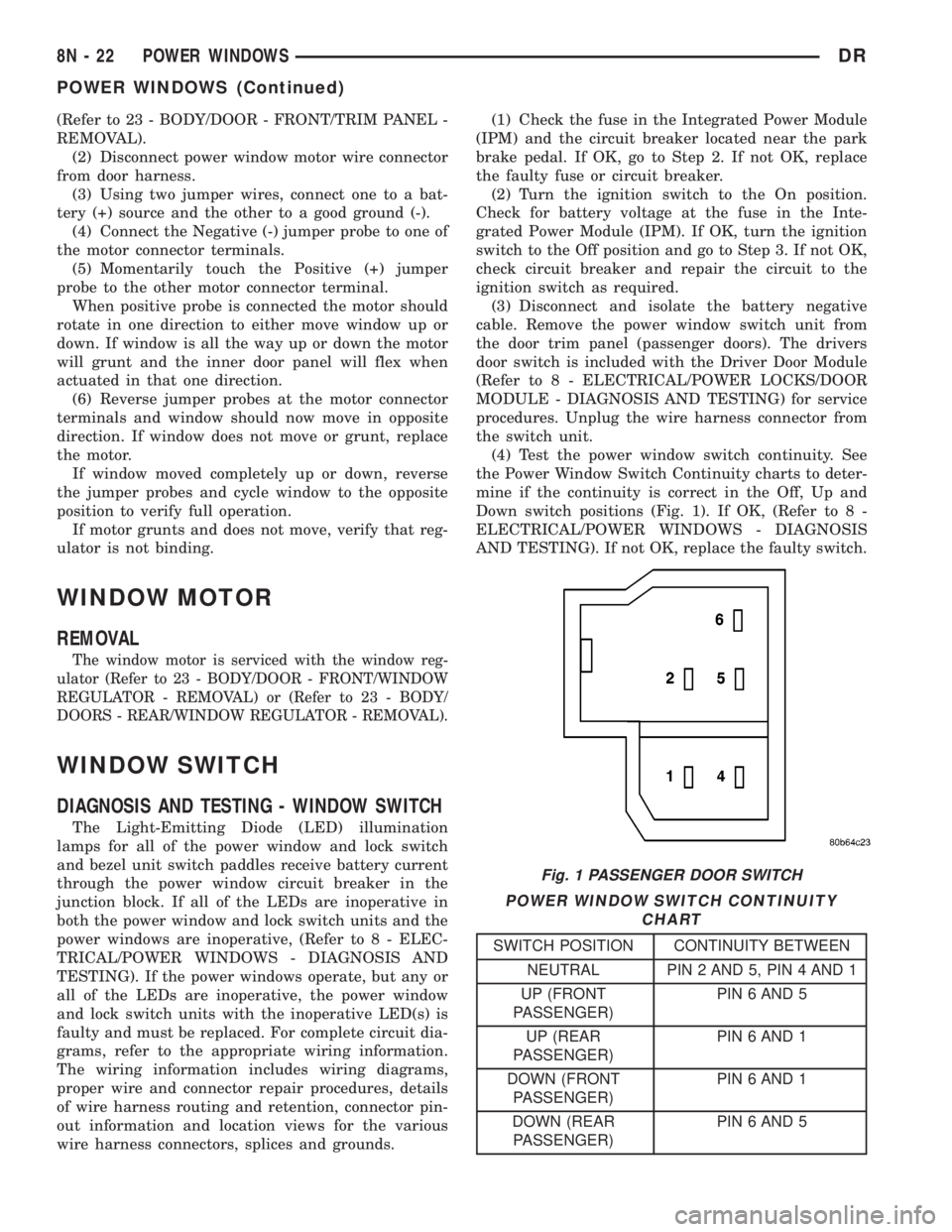
(4) Test the power window switch continuity. See
the Power Window Switch Continuity charts to deter-
mine if the continuity is correct in the Off, Up and
Down switch positions (Fig. 1). If OK, (Refer to 8 -
ELECTRICAL/POWER WINDOWS - DIAGNOSIS
AND TESTING). If not OK, replace the faulty switch.
POWER WINDOW SWITCH CONTINUITY
CHART
SWITCH POSITION CONTINUITY BETWEEN
NEUTRAL PIN 2 AND 5, PIN 4 AND 1
UP (FRONT
PASSENGER)PIN 6 AND 5
UP (REAR
PASSENGER)PIN 6 AND 1
DOWN (FRONT
PASSENGER)PIN 6 AND 1
DOWN (REAR
PASSENGER)PIN 6 AND 5
Fig. 1 PASSENGER DOOR SWITCH
8N - 22 POWER WINDOWSDR
POWER WINDOWS (Continued)
Page 2820 of 2895
STANDARD PROCEDURE - REFRIGERANT SYS-
TEM EVACUATE)
(7) Charge the refrigerant system. (Refer to 24 -
HEATING & AIR CONDITIONING/PLUMBING -
STANDARD PROCEDURE - REFRIGERANT SYS-
TEM CHARGE)
LIQUID LINE
REMOVAL
WARNING: REVIEW THE WARNINGS AND CAU-
TIONS IN THE FRONT OF THIS SECTION BEFORE
PERFORMING THE FOLLOWING OPERATION.
(Refer to 24 - HEATING & AIR CONDITIONING/
PLUMBING - WARNING) (Refer to 24 - HEATING &
AIR CONDITIONING/PLUMBING - CAUTION)
(1) Disconnect and isolate the battery negative
cable.
NOTE: Removal of the second battery and battery
tray is required on the diesel equipped vehicles.
(2) Remove rightside battery(Refer to 8 - ELEC-
TRICAL/BATTERY SYSTEM/BATTERY - REMOV-
AL).
(3) Remove rightside battery tray(Refer to 8 -
ELECTRICAL/BATTERY SYSTEM/TRAY - REMOV-
AL).
(4) Recover the refrigerant from the refrigerant
system. (Refer to 24 - HEATING & AIR CONDI-
TIONING/PLUMBING - STANDARD PROCEDURE -
REFRIGERANT RECOVERY)
(5) Disconnect the liquid line refrigerant line cou-
plers at the condenser outlet the mid point connec-
tion and the evaporator inlet. (Refer to 24 -
HEATING & AIR CONDITIONING/PLUMBING -
STANDARD PROCEDURE - A/C LINE COUPLERS)
Install plugs in, or tape over all of the opened refrig-
erant line fittings.
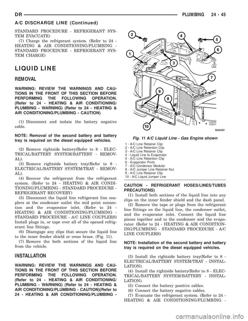
(6) Disengage any clips that secure the liquid line
to the inner fender shield or cross brace. (Fig. 11).
(7) Remove the both sections of the liquid line
from the vehicle.
INSTALLATION
WARNING: REVIEW THE WARNINGS AND CAU-
TIONS IN THE FRONT OF THIS SECTION BEFORE
PERFORMING THE FOLLOWING OPERATION.
(Refer to 24 - HEATING & AIR CONDITIONING/
PLUMBING - WARNING) (Refer to 24 - HEATING &
AIR CONDITIONING/PLUMBING - CAUTION)(Refer to
24 - HEATING & AIR CONDITIONING/PLUMBING -CAUTION - REFRIGERANT HOSES/LINES/TUBES
PRECAUTIONS)
(1) Install both sections of the liquid line into any
clips on the inner fender shield and the dash panel.
(2) Remove the tape or plugs from the refrigerant
line fittings on the liquid line, the condenser outlet,
and the evaporator inlet. Connect the liquid line
pieces together and to the condenser and the evapo-
rator. (Refer to 24 - HEATING & AIR CONDITION-
ING/PLUMBING - STANDARD PROCEDURE - A/C
LINE COUPLERS)
NOTE: Installation of the second battery and battery
tray is required on the diesel equipped vehicles.
(3) Install the rightside battery tray(Refer to 8 -
ELECTRICAL/BATTERY SYSTEM/TRAY - INSTAL-
LATION).
(4) Install the rightside battery(Refer to 8 - ELEC-
TRICAL/BATTERY SYSTEM/BATTERY - INSTAL-
LATION).
(5) Connect the battery positive cables.
(6) Connect the battery negative cables.
(7) Evacuate the refrigerant system. (Refer to 24 -
HEATING & AIR CONDITIONING/PLUMBING -
Fig. 11 A/C Liquid Line - Gas Engine shown
1 - A/C Line Retainer Clip
2 - A/C Line Retention Clip
3 - A/C Line Retainer Clip
4 - Liquid Line to Evaporator
5 - A/C Line Retention Clip
6 - Evaporator Ports
7 - A/C Condensor Modular
8 - A/C Jumper Line Retainer Nut
9 - A/C Line Retainer Clip
10 - A/C Liquid Jumper Line
DRPLUMBING 24 - 45
A/C DISCHARGE LINE (Continued)
Page 2874 of 2895

JOINT - INSTALLATION, UPPER BALL.....2-33
JOINT - REMOVAL, LOWER BALL.....2-18,2-32
JOINT - REMOVAL, UPPER BALL.........2-33
JOINT-INNER - INSTALLATION, CV........3-16
JOINT-INNER - REMOVAL, CV............3-16
JOINT-OUTER - INSTALLATION, CV........3-13
JOINT-OUTER - REMOVAL, CV...........3-13
JOINTS - ASSEMBLY, SINGLE CARDAN
UNIVERSAL...........................3-9
JOINTS - DISASSEMBLY, SINGLE
CARDAN UNIVERSAL...................3-9
JOUNCE BUMPER - INSTALLATION.......2-40
JOUNCE BUMPER - REMOVAL...........2-40
JOURNAL CLEARANCE - STANDARD
PROCEDURE, CONNECTING ROD
BEARING AND CRANKSHAFT...........9-321
JUMP STARTING - STANDARD
PROCEDURE.........................0-13
JUNCTION BLOCK - INSTALLATION,
BRAKE..............................5-19
JUNCTION BLOCK - REMOVAL, BRAKE....5-19
KEY CYLINDER - INSTALLATION.........19-12
KEY CYLINDER - REMOVAL............19-12
KEY IMMOBILIZER MODULE -
DESCRIPTION, SENTRY................8E-13
KEY IMMOBILIZER MODULE -
INSTALLATION, SENTRY...............8E-15
KEY IMMOBILIZER MODULE -
OPERATION, SENTRY.................8E-13
KEY IMMOBILIZER MODULE - REMOVAL,
SENTRY............................8E-15
KEY IMMOBILIZER SYSTEM INDICATOR
LAMP - DESCRIPTION, SENTRY..........8Q-5
KEY IMMOBILIZER SYSTEM INDICATOR
LAMP - OPERATION, SENTRY...........8Q-5
KEY IMMOBILIZER SYSTEM
INITIALIZATION, STANDARD
PROCEDURE - SENTRY................8Q-3
KEY IMMOBILIZER SYSTEM (SKIS),
DESCRIPTION - SENTRY................8Q-1
KEY IMMOBILIZER SYSTEM
TRANSPONDER PROGRAMMING,
STANDARD PROCEDURE - SENTRY.......8Q-4
KEY LOCK CYLINDER - DIAGNOSIS AND
TESTING, IGNITION SWITCH............19-11
KEY-IN IGNITION SWITCH -
DESCRIPTION.......................19-11
KEYLESS ENTRY MODULE -
DESCRIPTION, REMOTE................8N-7
KEYLESS ENTRY MODULE - DIAGNOSIS
AND TESTING, REMOTE................8N-8
KEYLESS ENTRY MODULE -
INSTALLATION, REMOTE...............8N-8
KEYLESS ENTRY MODULE - OPERATION,
REMOTE............................8N-8
KEYLESS ENTRY MODULE - REMOVAL,
REMOTE............................8N-8
KEYLESS ENTRY TRANSMITTER -
DIAGNOSIS AND TESTING, REMOTE......8N-8
KEYLESS ENTRY TRANSMITTER -
SPECIFICATIONS, REMOTE.............8N-10
KNOCK SENSOR - DESCRIPTION.........8I-25
KNOCK SENSOR - INSTALLATION........8I-26
KNOCK SENSOR - OPERATION..........8I-25
KNOCK SENSOR - REMOVAL............8I-25
KNUCKLE - DESCRIPTION...............2-17
KNUCKLE - INSTALLATION..........2-18,2-34
KNUCKLE - OPERATION................2-17
KNUCKLE - REMOVAL..............2-17,2-34
LABEL - DESCRIPTION, VEHICLE SAFETY
CERTIFICATION.....................Intro.-1
LAMP - DESCRIPTION, DOME...........8L-24
LAMP - DESCRIPTION, READING........8L-26
LAMP - DESCRIPTION, SENTRY KEY
IMMOBILIZER SYSTEM INDICATOR.......8Q-5
LAMP - INSTALLATION, BACKUP.........8L-7
LAMP - INSTALLATION, BRAKE..........8L-8
LAMP - INSTALLATION, CAB CLEARANCE . 8L-10
LAMP - INSTALLATION, CENTER HIGH
MOUNTED STOP.....................8L-10
LAMP - INSTALLATION, DOME..........8L-24
LAMP - INSTALLATION, FOG............8L-11
LAMP - INSTALLATION, LICENSE PLATE
. . 8L-16
LAMP - INSTALLATION, PARK/TURN
SIGNAL
............................8L-21
LAMP - INSTALLATION, READING
........8L-26
LAMP - INSTALLATION, TAIL
...........8L-21
LAMP - INSTALLATION, TURN
..........8L-22LAMP - INSTALLATION, UNDERHOOD....8L-22
LAMP - OPERATION, DOME............8L-24
LAMP - OPERATION, READING..........8L-26
LAMP - OPERATION, SENTRY KEY
IMMOBILIZER SYSTEM INDICATOR.......8Q-5
LAMP - REMOVAL, BACKUP.............8L-7
LAMP - REMOVAL, BRAKE..............8L-8
LAMP - REMOVAL, CAB CLEARANCE.....8L-10
LAMP - REMOVAL, CENTER HIGH
MOUNTED STOP.....................8L-10
LAMP - REMOVAL, DOME..............8L-24
LAMP - REMOVAL, FOG...............8L-11
LAMP - REMOVAL, LICENSE PLATE......8L-16
LAMP - REMOVAL, PARK/TURN SIGNAL . . 8L-21
LAMP - REMOVAL, READING...........8L-26
LAMP - REMOVAL, TAIL...............8L-21
LAMP - REMOVAL, TURN..............8L-22
LAMP - REMOVAL, UNDERHOOD........8L-22
LAMP INDICATOR - DESCRIPTION,
CARGO.............................8J-20
LAMP INDICATOR - OPERATION, CARGO . . 8J-20
LAMP (MIL) - DESCRIPTION,
MALFUNCTION INDICATOR.............8J-30
LAMP (MIL) - OPERATION,
MALFUNCTION INDICATOR.............8J-30
LAMP OUT INDICATOR - DESCRIPTION . . . 8J-28
LAMP OUT INDICATOR - OPERATION.....8J-28
LAMP RELAY - DESCRIPTION, FOG........8L-11
LAMP RELAY - DESCRIPTION, PARK.....8L-19
LAMP RELAY - DIAGNOSIS AND
TESTING, FRONT FOG.................8L-12
LAMP RELAY - DIAGNOSIS AND
TESTING, PARK......................8L-20
LAMP RELAY - INSTALLATION, FOG......8L-13
LAMP RELAY - INSTALLATION, PARK.....8L-21
LAMP RELAY - OPERATION, FOG........8L-12
LAMP RELAY - OPERATION, PARK.......8L-19
LAMP RELAY - REMOVAL, FOG.........8L-13
LAMP RELAY - REMOVAL, PARK........8L-20
LAMP REPLACEMENT - STANDARD
PROCEDURE, MODULE................8M-3
LAMP REPLACEMENT - STANDARD
PROCEDURE, READING/COURTESY.......8M-3
LAMP SWITCH - DESCRIPTION, BACKUP . . . 8L-7
LAMP SWITCH - DESCRIPTION, BRAKE....8L-8
LAMP SWITCH - DIAGNOSIS AND
TESTING, BACKUP.....................8L-8
LAMP SWITCH - DIAGNOSIS AND
TESTING, BRAKE......................8L-9
LAMP SWITCH - INSTALLATION, BRAKE . . 8L-10
LAMP SWITCH - OPERATION, BACKUP....8L-8
LAMP SWITCH - OPERATION, BRAKE......8L-8
LAMP SWITCH - REMOVAL, BRAKE.......8L-9
LAMP UNIT - INSTALLATION, CENTER
HIGH MOUNTED STOP................8L-10
LAMP UNIT - INSTALLATION, LICENSE
PLATE .............................8L-16
LAMP UNIT - INSTALLATION, TAIL.......8L-21
LAMP UNIT - INSTALLATION,
UNDERHOOD........................8L-23
LAMP UNIT - REMOVAL, CENTER HIGH
MOUNTED STOP.....................8L-10
LAMP UNIT - REMOVAL, LICENSE PLATE . . 8L-16
LAMP UNIT - REMOVAL, TAIL...........8L-21
LAMP UNIT - REMOVAL, UNDERHOOD . . . 8L-22
LAMPS, SPECIFICATIONS - EXTERIOR.....8L-7
LAMPS/LIGHTING - EXTERIOR -
DESCRIPTION........................8L-2
LAMPS/LIGHTING - EXTERIOR -
DIAGNOSIS AND TESTING..............8L-3
LAMPS/LIGHTING - EXTERIOR -
OPERATION..........................8L-2
LAMP/SWITCH - INSTALLATION, GLOVE
BOX ...............................8L-25
LAMP/SWITCH - REMOVAL, GLOVE BOX . . 8L-25
LASH ADJUSTER - DIAGNOSIS AND
TESTING, HYDRAULIC.............9-124,9-31
LASH ADJUSTMENT AND VERIFICATION
- STANDARD PROCEDURE, VALVE.......9-308
LATCH - INSTALLATION.....23-16,23-23,23-32,
23-47
LATCH - INSTALLATION, GLOVE BOX
.....23-53
LATCH - INSTALLATION, UNDER SEAT
STORAGE BIN
.......................23-81
LATCH - REMOVAL
....23-16,23-23,23-32,23-47
LATCH - REMOVAL, GLOVE BOX
.........23-53
LATCH - REMOVAL, UNDER SEAT
STORAGE BIN
.......................23-81LATCH RELEASE CABLE/HANDLE
ASSEMBLY - INSTALLATION............23-47
LATCH RELEASE CABLE/HANDLE
ASSEMBLY - REMOVAL................23-47
LATCH STRIKER - INSTALLATION . . 23-17,23-24,
23-33
LATCH STRIKER - REMOVAL . 23-17,23-24,23-33
LATCH STRIKER / SECONDARY CATCH -
INSTALLATION.......................23-48
LATCH STRIKER / SECONDARY CATCH -
REMOVAL..........................23-48
LD & HD EXCEPT 4X4 HD -
INSTALLATION, ALL..................19-15
LD & HD EXCEPT 4X4 HD - REMOVAL,
ALL ...............................19-14
LEAD - DIAGNOSIS AND TESTING,
TIRE/VEHICLE........................22-8
LEAK - DIAGNOSIS AND TESTING,
CONVERTER HOUSING FLUID . . . 21-143,21-324,
21-495
LEAK - DIAGNOSIS AND TESTING,
ENGINE OIL................9-150,9-214,9-63
LEAK DETECTION ASSY - DESCRIPTION,
NATURAL VAC.......................25-23
LEAK DETECTION ASSY - INSTALLATION,
NATURAL VAC.......................25-24
LEAK DETECTION ASSY - OPERATION,
NATURAL VAC.......................25-23
LEAK DETECTION ASSY - REMOVAL,
NATURAL VAC.......................25-24
LEAK DETECTION PUMP - DESCRIPTION . . 25-13
LEAK DETECTION PUMP - INSTALLATION . 25-16
LEAK DETECTION PUMP - OPERATION.....25-14
LEAK DETECTION PUMP - REMOVAL.....25-16
LEAKAGE - DIAGNOSIS AND TESTING,
CYLINDER COMBUSTION PRESSURE....9-182,
9-231,9-359,9-8,9-92
LEAKAGE - DIAGNOSIS AND TESTING,
INTAKE MANIFOLD....9-157,9-219,9-274,9-401
LEAKAGE - DIAGNOSIS AND TESTING,
PUMP.............................19-39
LEAKS - DIAGNOSIS AND TESTING,
CHARGE AIR COOLER SYSTEM.........11-15
LEAKS - DIAGNOSIS AND TESTING,
COOLING SYSTEM - TESTING.............7-5
LEAKS - DIAGNOSIS AND TESTING,
ENGINE OIL....................9-269,9-394
LEAKS - DIAGNOSIS AND TESTING,
HIGH-PRESSURE FUEL LINE............14-69
LEAKS - DIAGNOSIS AND TESTING,
INTAKE MANIFOLD....................9-71
LEAKS - DIAGNOSIS AND TESTING,
REAR SEAL AREA...........9-135,9-204,9-64
LEAKS - DIAGNOSIS AND TESTING,
REFRIGERANT SYSTEM...............24-51
LEAKS - DIAGNOSIS AND TESTING,
WATER .............................23-1
LEAKS - STANDARD PROCEDURE,
REPAIRING.........................22-10
LEARN - STANDARD PROCEDURE,
DRIVE.............................8E-21
LEARN - STANDARD PROCEDURE, TCM
QUICK.............................8E-21
LEFT - DESCRIPTION, CAMSHAFT(S).....9-113
LEFT - INSTALLATION..................2-34
LEFT - INSTALLATION, CAMSHAFT(S)....9-114
LEFT - INSTALLATION, CYLINDER HEAD . . . 9-23
LEFT - REMOVAL......................2-34
LEFT - REMOVAL, CAMSHAFT(S)........9-113
LEFT - REMOVAL, CYLINDER HEAD.......9-21
LEFT CYLINDER HEAD - INSTALLATION . . . 9-110
LEFT CYLINDER HEAD - REMOVAL.......9-106
LEFT OUTBOARD - INSTALLATION,
CENTER............................8O-45
LEFT OUTBOARD - REMOVAL, CENTER . . . 8O-43
LEFT REAR CABLE - INSTALLATION.......5-33
LEFT REAR CABLE - REMOVAL...........5-32
LEFT SIDE - INSTALLATION............9-122
LEFT SIDE - REMOVAL
................9-121
LENS REPLACEMENT - STANDARD
PROCEDURE, MODULE
................8M-3
LEVEL - DIAGNOSIS AND TESTING,
EFFECTS OF INCORRECT FLUID
. . 21-201,21-381,
21-541
LEVEL - STANDARD PROCEDURE,
BRAKE FLUID
........................5-18
LEVEL - STANDARD PROCEDURE,
ENGINE OIL
.........................9-341
DRINDEX 19
Description Group-Page Description Group-Page Description Group-Page
Page 2887 of 2895

SIDE - REMOVAL, LEFT................9-121
SIDE - REMOVAL, RIGHT..............9-121
SIDE BEZEL - INSTALLATION,
INSTRUMENT PANEL DRIVER...........23-59
SIDE BEZEL - REMOVAL, INSTRUMENT
PANEL DRIVER......................23-58
SIDE CURTAIN AIRBAG - DESCRIPTION . . . 8O-51
SIDE CURTAIN AIRBAG - INSTALLATION . . 8O-53
SIDE CURTAIN AIRBAG - OPERATION....8O-51
SIDE CURTAIN AIRBAG - REMOVAL......8O-52
SIDE IMPACT AIRBAG CONTROL
MODULE - DESCRIPTION..............8O-53
SIDE IMPACT AIRBAG CONTROL
MODULE - OPERATION................8O-54
SIDE MOLDINGS - INSTALLATION, BODY . . 23-36
SIDE MOLDINGS - REMOVAL, BODY.....23-36
SIDE VIEW MIRROR - INSTALLATION.....23-41
SIDE VIEW MIRROR - REMOVAL........23-41
SIDE VIEW MIRROR FLAG -
INSTALLATION.......................23-27
SIDE VIEW MIRROR FLAG - REMOVAL . . . 23-27
SIDE VIEW MIRROR GLASS -
INSTALLATION.......................23-44
SIDE VIEW MIRROR GLASS - REMOVAL . . 23-42
SIDEVIEW MIRROR - REMOVAL.........8N-13
SIGNAL INDICATOR - DESCRIPTION,
TURN..............................8J-39
SIGNAL INDICATOR - OPERATION, TURN . . 8J-39
SIGNAL LAMP - INSTALLATION,
PARK/TURN.........................8L-21
SIGNAL LAMP - REMOVAL, PARK/TURN . . 8L-21
SIGNAL SYSTEM - DESCRIPTION, TURN . . 8L-17
SIGNAL SYSTEM - OPERATION, TURN....8L-18
SILL TRIM COVER - INSTALLATION,
REAR DOOR........................23-72
SILL TRIM COVER - REMOVAL, REAR
DOOR.............................23-72
SINGLE CARDAN UNIVERSAL JOINTS -
ASSEMBLY...........................3-9
SINGLE CARDAN UNIVERSAL JOINTS -
DISASSEMBLY.........................3-9
SIZE, SPARE WHEEL WITH MATCHING
TIRE - DESCRIPTION, FULL............22-15
SKID PLATE - INSTALLATION, FRONT.....13-24
SKID PLATE - INSTALLATION, TRANSFER
CASE..............................13-26
SKID PLATE - REMOVAL, FRONT........13-24
SKID PLATE - REMOVAL, TRANSFER
CASE..............................13-26
SLEEVE - INSTALLATION, HEADREST.....23-82
SLEEVE - REMOVAL, HEADREST........23-82
SMOKE DIAGNOSIS CHARTS -
DIAGNOSIS AND TESTING.............9-285
SOLENOID - DESCRIPTION......21-253,21-431
SOLENOID - DESCRIPTION, EVAP/PURGE . 25-12
SOLENOID - INSTALLATION, EVAP/
PURGE.............................25-13
SOLENOID - OPERATION........21-254,21-431
SOLENOID - OPERATION, EVAP/PURGE . . . 25-12
SOLENOID - REMOVAL, EVAP/PURGE.....25-13
SOLENOID SWITCH VALVE -
DESCRIPTION......................21-574
SOLENOID SWITCH VALVE - OPERATION . 21-574
SOLENOIDS - DESCRIPTION...........21-574
SOLENOIDS - OPERATION.............21-575
SOLENOID/TRS ASSEMBLY -
DESCRIPTION, TRANSMISSION........21-582
SOLENOID/TRS ASSEMBLY -
INSTALLATION, TRANSMISSION........21-583
SOLENOID/TRS ASSEMBLY -
OPERATION, TRANSMISSION..........21-582
SOLENOID/TRS ASSEMBLY - REMOVAL,
TRANSMISSION.....................21-583
SOLID LIFTERS/TAPPETS - CLEANING....9-328
SOLID LIFTERS/TAPPETS - INSPECTION . . 9-328
SOLID LIFTERS/TAPPETS -
INSTALLATION.......................9-328
SOLID LIFTERS/TAPPETS - REMOVAL....9-327
SPARE / TEMPORARY TIRE -
DESCRIPTION.......................22-15
SPARE TIRE / TEMPORARY -
DESCRIPTION........................22-5
SPARE WHEEL WITH MATCHING TIRE -
DESCRIPTION, FULL SIZE
..............22-15
SPARK PLUG - DESCRIPTION
...........8I-27
SPARK PLUG - REMOVAL
..............8I-30
SPARK PLUG CABLE - DESCRIPTION
.....8I-33
SPARK PLUG CABLE - INSTALLATION
.....8I-35SPARK PLUG CABLE - OPERATION.......8I-33
SPARK PLUG CABLE - REMOVAL........8I-34
SPARK PLUG CABLE ORDER, 8.0L V-10
ENGINE..............................8I-5
SPARK PLUG CABLE RESISTANCE,
SPECIFICATIONS......................8I-5
SPARK PLUG CABLES - DIAGNOSIS AND
TESTING............................8I-33
SPARK PLUG CONDITIONS - DIAGNOSIS
AND TESTING........................8I-27
SPARK PLUGS, SPECIFICATIONS..........8I-5
SPEAKER - DESCRIPTION..............8A-12
SPEAKER - DIAGNOSIS AND TESTING....8A-13
SPEAKER - INSTALLATION.............8A-15
SPEAKER - OPERATION...............8A-12
SPEAKER - REMOVAL.................8A-13
SPECIFICATIONS......................7-20
SPEED CONTROL - DESCRIPTION........8P-1
SPEED CONTROL - OPERATION..........8P-2
SPEED CONTROL - TORQUE.............8P-3
SPEED SENSOR - DESCRIPTION . . 21-254,21-431
SPEED SENSOR - DESCRIPTION, FRONT
WHEEL.............................5-41
SPEED SENSOR - DESCRIPTION, INPUT . 21-558
SPEED SENSOR - DESCRIPTION,
OUTPUT...........................21-567
SPEED SENSOR - DIAGNOSIS AND
TESTING, REAR WHEEL................5-43
SPEED SENSOR - INSTALLATION, FRONT
WHEEL.............................5-42
SPEED SENSOR - INSTALLATION, INPUT . 21-559
SPEED SENSOR - INSTALLATION,
OUTPUT...........................21-567
SPEED SENSOR - INSTALLATION, REAR
WHEEL.............................5-43
SPEED SENSOR - OPERATION . . . 21-254,21-431
SPEED SENSOR - OPERATION, FRONT
WHEEL.............................5-41
SPEED SENSOR - OPERATION, INPUT . . . 21-558
SPEED SENSOR - OPERATION, OUTPUT . . 21-567
SPEED SENSOR - REMOVAL, FRONT
WHEEL.............................5-41
SPEED SENSOR - REMOVAL, INPUT.....21-559
SPEED SENSOR - REMOVAL, OUTPUT . . . 21-567
SPEED SENSOR - REMOVAL, REAR
WHEEL.............................5-42
SPEEDOMETER - DESCRIPTION.........8J-36
SPEEDOMETER - OPERATION...........8J-36
SPEEDS - DESCRIPTION, TIRE
PRESSURE FOR HIGH..................22-6
SPLASH SHIELD - INSTALLATION,
FRONT WHEELHOUSE.................23-41
SPLASH SHIELD - INSTALLATION, REAR
WHEELHOUSE.......................23-41
SPLASH SHIELD - REMOVAL, FRONT
WHEELHOUSE.......................23-40
SPLASH SHIELD - REMOVAL, REAR
WHEELHOUSE.......................23-41
SPLICE INFORMATION - DESCRIPTION,
CONNECTOR, GROUND..............8W-01-7
SPLICING - STANDARD PROCEDURE,
WIRE...........................8W-01-15
SPRING - DESCRIPTION................2-41
SPRING - INSTALLATION.......2-22,2-36,2-41
SPRING - OPERATION..................2-41
SPRING - REMOVAL...........2-21,2-36,2-41
SPRING AND SHOCK - DIAGNOSIS AND
TESTING............................2-38
SPRING BUMPERS (3500) -
INSTALLATION, AUXILIARY..............2-40
SPRING BUMPERS (3500) - REMOVAL,
AUXILIARY..........................2-40
SPRING TIP INSERTS - INSTALLATION....2-42
SPRING TIP INSERTS - REMOVAL........2-41
SPRINGS - DESCRIPTION, VALVE . . . 9-125,9-31,
9-36
SPRINGS - INSTALLATION, VALVE . . 9-126,9-199,
9-31,9-37
SPRINGS - INSTALLATION, VALVES AND
VALVE
.............................9-379
SPRINGS - REMOVAL, VALVE
. 9-125,9-199,9-31,
9-37
SPRINGS - REMOVAL, VALVES AND
VALVE
.............................9-377
SPRINGS - STANDARD PROCEDURE,
VALVES, GUIDES
................9-246,9-305
SPRINGS AND SEALS - REMOVAL,
VALVE
.............................9-308SPROCKETS - INSPECTION, TIMING
BELT/CHAIN.....................9-171,9-83
SPROCKETS - INSTALLATION, TIMING
BELT/CHAIN...........9-172,9-279,9-406,9-84
SPROCKETS - INSTALLATION,
TIMING/CHAIN.......................9-222
SPROCKETS - REMOVAL, TIMING
BELT/CHAIN...........9-169,9-279,9-405,9-81
SPROCKETS - REMOVAL, TIMING/CHAIN . . 9-221
SQUEAK & RATTLE - STANDARD
PROCEDURE, BUZZ...................23-11
STABILIZER BAR - DESCRIPTION.........2-24
STABILIZER BAR - INSTALLATION....2-24,2-37
STABILIZER BAR - OPERATION...........2-24
STABILIZER BAR - REMOVAL........2-24,2-37
STAKING - STANDARD PROCEDURE,
HEAT ...............................23-3
STANDARD CAB - INSTALLATION........8O-31
STANDARD CAB - REMOVAL...........8O-28
STARTER MOTOR - DIAGNOSIS AND
TESTING...........................8F-34
STARTER MOTOR - INSTALLATION.......8F-37
STARTER MOTOR - REMOVAL..........8F-34
STARTER MOTOR RELAY - DESCRIPTION . 8F-38
STARTER MOTOR RELAY -
INSTALLATION.......................8F-39
STARTER MOTOR RELAY - OPERATION . . . 8F-38
STARTER MOTOR RELAY - REMOVAL.....8F-39
STARTER RELAY - DIAGNOSIS AND
TESTING.............................8F-38
STARTING - DESCRIPTION.............8F-28
STARTING - OPERATION...............8F-28
STARTING - STANDARD PROCEDURE,
JUMP...............................0-13
STARTING SYSTEM - DIAGNOSIS AND
TESTING...........................8F-29
STARTING SYSTEM - SPECIFICATIONS,
TORQUE............................8F-34
STARTING SYSTEM, SPECIFICATIONS.....8F-33
STATE DISPLAY TEST MODE -
DESCRIPTION........................25-1
STEERING - DESCRIPTION..............19-1
STEERING - OPERATION................19-1
STEERING COLUMN - DIAGNOSIS AND
TESTING............................19-7
STEERING COLUMN OPENING COVER -
INSTALLATION.......................23-61
STEERING COLUMN OPENING COVER -
REMOVAL..........................23-61
STEERING COLUMN OPENING SUPPORT
BRACKET - INSTALLATION.............23-62
STEERING COLUMN OPENING SUPPORT
BRACKET - REMOVAL.................23-61
STEERING COUPLING - INSTALLATION,
UPPER.............................19-14
STEERING COUPLING - REMOVAL,
UPPER.............................19-13
STEERING FLOW AND PRESSURE -
DIAGNOSIS AND TESTING, POWER.......19-4
STEERING FLUID - DESCRIPTION,
POWER..............................0-3
STEERING FLUID LEVEL CHECKING -
STANDARD PROCEDURE, POWER.......19-42
STEERING GEAR INPUT SHAFT SEAL -
INSTALLATION.......................19-28
STEERING GEAR INPUT SHAFT SEAL -
REMOVAL..........................19-25
STEERING GEAR, SPECIAL TOOLS -
POWER............................19-22
STEERING GEAR, SPECIFICATIONS -
POWER............................19-21
STEERING LINKAGE, SPECIAL TOOLS....19-35
STEERING PRESSURE SWITCH -
DESCRIPTION, POWER................19-45
STEERING PRESSURE SWITCH -
OPERATION, POWER..................19-45
STEERING PUMP - INITIAL OPERATION -
STANDARD PROCEDURE, POWER.......19-39
STEERING, SPECIAL TOOLS.............19-5
STEERING SYSTEM - DIAGNOSIS AND
TESTING, POWER.....................19-2
STEERING SYSTEM - STANDARD
PROCEDURE, FLUSHING POWER
........19-39
STEERING WHEEL - INSTALLATION
......19-15
STEERING WHEEL - REMOVAL
..........19-15
STEM SEAL - INSTALLATION, VALVE
.....9-378
STEM SEALS - DESCRIPTION, VALVE
....9-126,
9-198
32 INDEXDR
Description Group-Page Description Group-Page Description Group-Page