jump start DODGE RAM 2003 Service Repair Manual
[x] Cancel search | Manufacturer: DODGE, Model Year: 2003, Model line: RAM, Model: DODGE RAM 2003Pages: 2895, PDF Size: 83.15 MB
Page 14 of 2895
LUBRICATION & MAINTENANCE
TABLE OF CONTENTS
page page
INTERNATIONAL SYMBOLS
DESCRIPTION..........................1
FLUID TYPES
DESCRIPTION
DESCRIPTION - FUEL REQUIREMENTS -
DIESEL ENGINE.......................1
DESCRIPTION - ENGINE OIL AND
LUBRICANTS.........................2
DESCRIPTION - POWER STEERING FLUID . . 3
DESCRIPTION - ENGINE COOLANT........3
DESCRIPTION - TRANSFER CASE - NV241
GENII...............................4
DESCRIPTION - TRANSFER CASE - NV271 . . 4
DESCRIPTION - TRANSFER CASE - NV243 . . 4
DESCRIPTION - TRANSFER CASE - NV273 . . 4
DESCRIPTION - AXLE...................4DESCRIPTION - MANUAL TRANSMISSION . . . 4
DESCRIPTION - AUTOMATIC
TRANSMISSION FLUID..................4
OPERATION - AUTOMATIC TRANSMISSION
FLUID...............................5
FLUID CAPACITIES
SPECIFICATIONS
FLUID CAPACITIES.....................5
MAINTENANCE SCHEDULES
DESCRIPTION..........................6
JUMP STARTING
STANDARD PROCEDURE - JUMP STARTING...13
HOISTING
STANDARD PROCEDURE - HOISTING.......14
TOWING
STANDARD PROCEDURE - TOWING........15
INTERNATIONAL SYMBOLS
DESCRIPTION
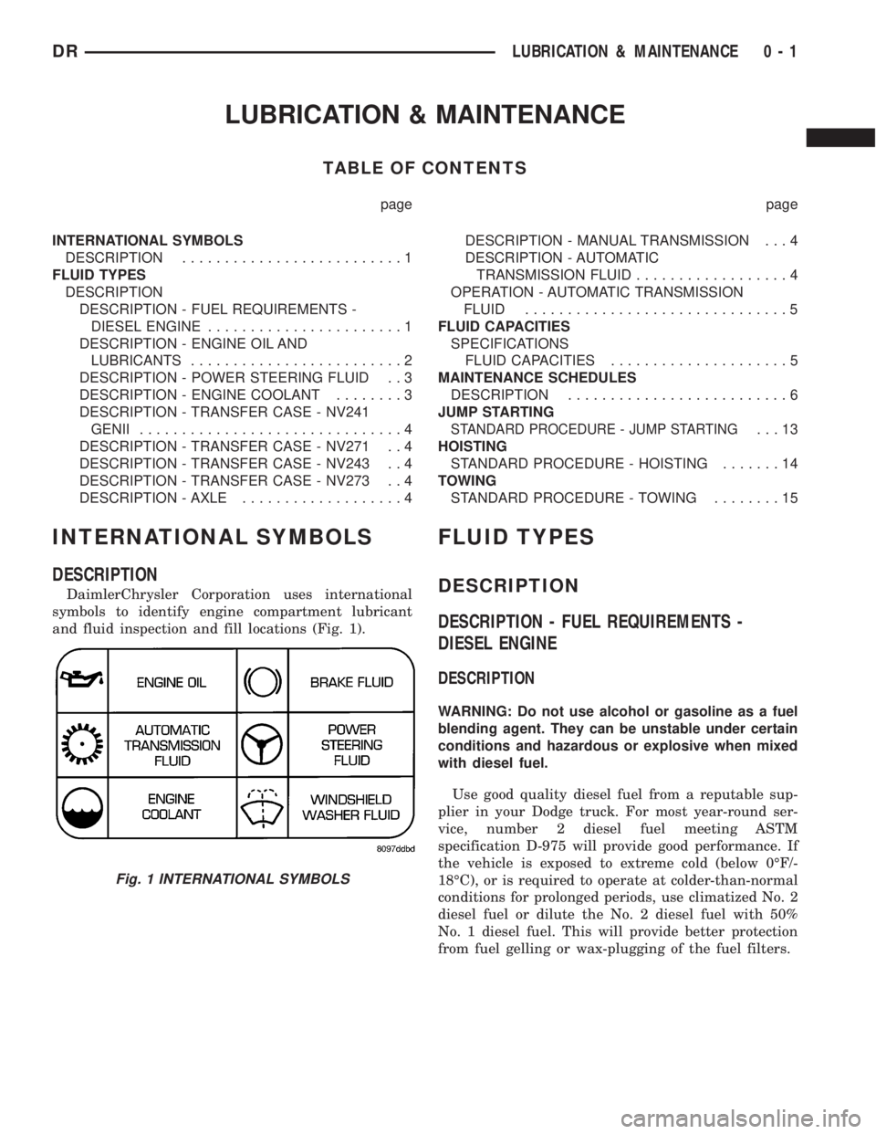
DaimlerChrysler Corporation uses international
symbols to identify engine compartment lubricant
and fluid inspection and fill locations (Fig. 1).
FLUID TYPES
DESCRIPTION
DESCRIPTION - FUEL REQUIREMENTS -
DIESEL ENGINE
DESCRIPTION
WARNING: Do not use alcohol or gasoline as a fuel
blending agent. They can be unstable under certain
conditions and hazardous or explosive when mixed
with diesel fuel.
Use good quality diesel fuel from a reputable sup-
plier in your Dodge truck. For most year-round ser-
vice, number 2 diesel fuel meeting ASTM
specification D-975 will provide good performance. If
the vehicle is exposed to extreme cold (below 0ÉF/-
18ÉC), or is required to operate at colder-than-normal
conditions for prolonged periods, use climatized No. 2
diesel fuel or dilute the No. 2 diesel fuel with 50%
No. 1 diesel fuel. This will provide better protection
from fuel gelling or wax-plugging of the fuel filters.
Fig. 1 INTERNATIONAL SYMBOLS
DRLUBRICATION & MAINTENANCE 0 - 1
Page 26 of 2895
JUMP STARTING
STANDARD PROCEDURE - JUMP STARTING
WARNING: REVIEW ALL SAFETY PRECAUTIONS
AND WARNINGS IN THE BATTERY SYSTEM SEC-
TION OF THE SERVICE MANUAL. (Refer to 8 -
ELECTRICAL/BATTERY SYSTEM/BATTERY - STAN-
DARD PROCEDURE)
²DO NOT JUMP START A FROZEN BATTERY,
PERSONAL INJURY CAN RESULT.
²IF EQUIPPED, DO NOT JUMP START WHEN
MAINTENANCE FREE BATTERY INDICATOR DOT IS
YELLOW OR BRIGHT COLOR.
²DO NOT JUMP START A VEHICLE WHEN THE
BATTERY FLUID IS BELOW THE TOP OF LEAD
PLATES.
²DO NOT ALLOW JUMPER CABLE CLAMPS TO
TOUCH EACH OTHER WHEN CONNECTED TO A
BOOSTER SOURCE.
²DO NOT USE OPEN FLAME NEAR BATTERY.
²REMOVE METALLIC JEWELRY WORN ON
HANDS OR WRISTS TO AVOID INJURY BY ACCI-
DENTAL ARCING OF BATTERY CURRENT.
²WHEN USING A HIGH OUTPUT BOOSTING
DEVICE, DO NOT ALLOW BATTERY VOLTAGE TO
EXCEED 16 VOLTS. REFER TO INSTRUCTIONS
PROVIDED WITH DEVICE BEING USED.
FAILURE TO FOLLOW THESE INSTRUCTIONS MAY
RESULT IN PERSONAL INJURY.
CAUTION: When using another vehicle as a
booster, do not allow vehicles to touch. Electrical
systems can be damaged on either vehicle.
TO JUMP START A DISABLED VEHICLE:
(1) Raise hood on disabled vehicle and visually
inspect engine compartment for:
²Battery cable clamp condition, clean if necessary.
²Frozen battery.
²Yellow or bright color test indicator, if equipped.
²Low battery fluid level.
²Generator drive belt condition and tension.
²Fuel fumes or leakage, correct if necessary.CAUTION: If the cause of starting problem on dis-
abled vehicle is severe, damage to booster vehicle
charging system can result.
(2) When using another vehicle as a booster
source, park the booster vehicle within cable reach.
Turn off all accessories, set the parking brake, place
the automatic transmission in PARK or the manual
transmission in NEUTRAL and turn the ignition
OFF.
(3) On disabled vehicle, place gear selector in park
or neutral and set park brake. Turn off all accesso-
ries.
(4) Connect jumper cables to booster battery. RED
clamp to positive terminal (+). BLACK clamp to neg-
ative terminal (-). DO NOT allow clamps at opposite
end of cables to touch, electrical arc will result.
Review all warnings in this procedure.
(5) On disabled vehicle, connect RED jumper cable
clamp to positive (+) terminal. Connect BLACK
jumper cable clamp to engine ground as close to the
ground cable attaching point as possible.
(6) Start the engine in the vehicle which has the
booster battery, let the engine idle a few minutes,
then start the engine in the vehicle with the dis-
charged battery.
CAUTION: Do not crank starter motor on disabled
vehicle for more than 15 seconds, starter will over-
heat and could fail.
(7) Allow battery in disabled vehicle to charge to
at least 12.4 volts (75% charge) before attempting to
start engine. If engine does not start within 15 sec-
onds, stop cranking engine and allow starter to cool
(15 min.), before cranking again.
DISCONNECT CABLE CLAMPS AS FOLLOWS:
²Disconnect BLACK cable clamp from engine
ground on disabled vehicle.
²When using a Booster vehicle, disconnect
BLACK cable clamp from battery negative terminal.
Disconnect RED cable clamp from battery positive
terminal.
²Disconnect RED cable clamp from battery posi-
tive terminal on disabled vehicle.
DRLUBRICATION & MAINTENANCE 0 - 13
Page 407 of 2895
For battery system maintenance schedules and
jump starting procedures, see the owner's manual in
the vehicle glove box. Optionally, refer to the Lubri-
cation and Maintenance section of this manual for
the proper battery jump starting procedure. While
battery charging can be considered a maintenance
procedure, the battery charging procedure and
related information are located later in this section of
the service manual. This was done because the bat-
tery must be fully-charged before any battery system
diagnosis or testing procedures can be performed.
OPERATION
The battery system is designed to provide a safe,
efficient, reliable and mobile means of delivering and
storing electrical energy. This electrical energy is
required to operate the engine starting system, as
well as to operate many of the other vehicle acces-
sory systems for limited durations while the engine
and/or the charging system are not operating. The
battery system is also designed to provide a reserve
of electrical energy to supplement the charging sys-
tem for short durations while the engine is running
and the electrical current demands of the vehicle
exceed the output of the charging system. In addition
to delivering, and storing electrical energy for the
vehicle, the battery system serves as a capacitor and
voltage stabilizer for the vehicle electrical system. It
absorbs most abnormal or transient voltages caused
by the switching of any of the electrical components
or circuits in the vehicle.
DIAGNOSIS AND TESTING - BATTERY SYSTEM
The battery, starting, and charging systems in the
vehicle operate with one another and must be tested
as a complete system. In order for the engine to start
and the battery to maintain its charge properly, all of
the components that are used in these systems must
perform within specifications. It is important thatthe battery, starting, and charging systems be thor-
oughly tested and inspected any time a battery needs
to be charged or replaced. The cause of abnormal bat-
tery discharge, overcharging or early battery failure
must be diagnosed and corrected before a battery is
replaced and before a vehicle is returned to service.
The service information for these systems has been
separated within this service manual to make it eas-
ier to locate the specific information you are seeking.
However, when attempting to diagnose any of these
systems, it is important that you keep their interde-
pendency in mind.
The diagnostic procedures used for the battery,
starting, and charging systems include the most
basic conventional diagnostic methods, to the more
sophisticated On-Board Diagnostics (OBD) built into
the Powertrain Control Module (PCM). Use of an
induction-type milliampere ammeter, a volt/ohmme-
ter, a battery charger, a carbon pile rheostat (load
tester), a 12-volt test lamp and/or special service
tools may be required. All OBD-sensed systems are
monitored by the PCM. Each monitored circuit is
assigned a Diagnostic Trouble Code (DTC). The PCM
will store a DTC in electronic memory for any failure
it detects. Always check the PCM for stored trouble
codes before returning the vehicle to service. Refer to
Charging System for the proper charging system test
procedures. Refer to Starting System for the proper
starting system test procedures.
MICRO 420 BATTERY TESTER
The Micro 420 automotive battery tester is
designed to help the dealership technician diagnose a
defective battery. Follow the instruction manual sup-
plied with the tester to properly diagnose a battery.
If the instruction manual is not available, refer to
the standard procedure in this section, which
includes the directions for using the Micro 420 bat-
tery tester.
8F - 2 BATTERY SYSTEMDR
BATTERY SYSTEM (Continued)
Page 439 of 2895
SPECIFICATIONS - TORQUE - STARTING
SYSTEM
DESCRIPTION N´m Ft. Lbs. In. Lbs.
Battery Cable Eyelet Nut at
Solenoid (large nut - gas engines)25 19 221
Battery Cable Eyelet Nut at
Solenoid (large nut - diesel engine)14 - 120
Starter Solenoid Nut (small nut -
diesel engine)6-55
Starter Mounting Bolts - Gas
Engines68 50 -
Starter Mounting Nut - Gas Engines 68 50 -
Starter Mounting Bolts - Diesel 43 32 -
STARTER MOTOR
DIAGNOSIS AND TESTING - STARTER MOTOR
Correct starter motor operation can be confirmed
by performing the following free running bench test.
This test can only be performed with starter motor
removed from vehicle. Refer to Specifications for
starter motor specifications.
(1) Remove starter motor from vehicle. Refer to
Starter Motor Removal and Installation.
(2) Mount starter motor securely in a soft-jawed
bench vise. The vise jaws should be clamped on the
mounting flange of starter motor. Never clamp on
starter motor by field frame.
(3) Connect a suitable volt-ampere tester and a
12-volt battery to starter motor in series, and set
ammeter to 100 ampere scale. See instructions pro-
vided by manufacturer of volt-ampere tester being
used.
(4) Install jumper wire from solenoid terminal to
solenoid battery terminal. The starter motor should
operate. If starter motor fails to operate, replace
faulty starter motor assembly.
(5) Adjust carbon pile load of tester to obtain free
running test voltage. Refer to Specifications for
starter motor free running test voltage specifications.
(6) Note reading on ammeter and compare reading
to free running test maximum amperage draw. Refer
to Specifications for starter motor free running test
maximum amperage draw specifications.
(7) If ammeter reading exceeds maximum amper-
age draw specification, replace faulty starter motor
assembly.
STARTER SOLENOID
This test can only be performed with starter motor
removed from vehicle.(1) Remove starter motor from vehicle. Refer to
Starter Motor Removal and Installation.
(2) Disconnect wire from solenoid field coil termi-
nal.
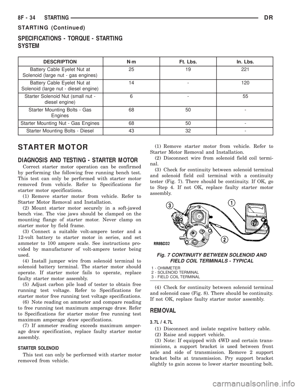
(3) Check for continuity between solenoid terminal
and solenoid field coil terminal with a continuity
tester (Fig. 7). There should be continuity. If OK, go
to Step 4. If not OK, replace faulty starter motor
assembly.
(4) Check for continuity between solenoid terminal
and solenoid case (Fig. 8). There should be continuity.
If not OK, replace faulty starter motor assembly.
REMOVAL
3.7L / 4.7L
(1) Disconnect and isolate negative battery cable.
(2) Raise and support vehicle.
(3) Note: If equipped with 4WD and certain trans-
missions, a support bracket is used between front
axle and side of transmission. Remove 2 support
bracket bolts at transmission. Pry support bracket
slightly to gain access to lower starter mounting bolt.
Fig. 7 CONTINUITY BETWEEN SOLENOID AND
FIELD COIL TERMINALS - TYPICAL
1 - OHMMETER
2 - SOLENOID TERMINAL
3 - FIELD COIL TERMINAL
8F - 34 STARTINGDR
STARTING (Continued)
Page 491 of 2895
CAUTION: Do not leave any one spark plug cable
disconnected for longer than necessary during test-
ing. This may cause possible heat damage to the
catalytic converter. Total test time must not exceed
ten minutes.
Except 5.7L V-8 :With the engine running,
remove spark plug cable from spark plug (one at a
time) and hold next to a good engine ground. If the
cable and spark plug are in good condition, the
engine rpm should drop and the engine will run
poorly. If engine rpm does not drop, the cable and/or
spark plug may not be operating properly and should
be replaced. Also check engine cylinder compression.
With the engine not running, connect one end of a
test probe to a good ground. Start the engine and run
the other end of the test probe along the entire
length of all spark plug cables. If cables are cracked
or punctured, there will be a noticeable spark jump
from the damaged area to the test probe. The cable
running from the ignition coil to the distributor cap
can be checked in the same manner. Cracked, dam-
aged or faulty cables should be replaced with resis-
tance type cable. This can be identified by the words
ELECTRONIC SUPPRESSION printed on the cable
jacket.Use an ohmmeter to test for open circuits, exces-
sive resistance or loose terminals. If equipped,
remove the distributor cap from the distributor.Do
not remove cables from cap.Remove cable from
spark plug. Connect ohmmeter to spark plug termi-
nal end of cable and to corresponding electrode in
distributor cap. Resistance should be 250 to 1000
Ohms per inch of cable. If not, remove cable from dis-
tributor cap tower and connect ohmmeter to the ter-
minal ends of cable. If resistance is not within
specifications as found in the SPARK PLUG CABLE
RESISTANCE chart, replace the cable. Test all spark
plug cables in this manner.
SPARK PLUG CABLE RESISTANCE
MINIMUM MAXIMUM
250 Ohms Per Inch 1000 Ohms Per Inch
3000 Ohms Per Foot 12,000 Ohms Per Foot
To test ignition coil-to-distributor cap cable (if
applicaple), do not remove the cable from the cap.
Connect ohmmeter to rotor button (center contact) of
distributor cap and terminal at ignition coil end of
cable. If resistance is not within specifications as
found in the Spark Plug Cable Resistance chart,
remove the cable from the distributor cap. Connect
the ohmmeter to the terminal ends of the cable. If
resistance is not within specifications as found in the
Spark Plug Cable Resistance chart, replace the cable.
Inspect the ignition coil tower for cracks, burns or
corrosion.
REMOVAL
5.9L V-8 / 8.0L V-10
CAUTION: When disconnecting a high voltage cable
from a spark plug or from the distributor cap, twist
the rubber boot slightly (1/2 turn) to break it loose
(Fig. 54). Grasp the boot (not the cable) and pull it
off with a steady, even force.
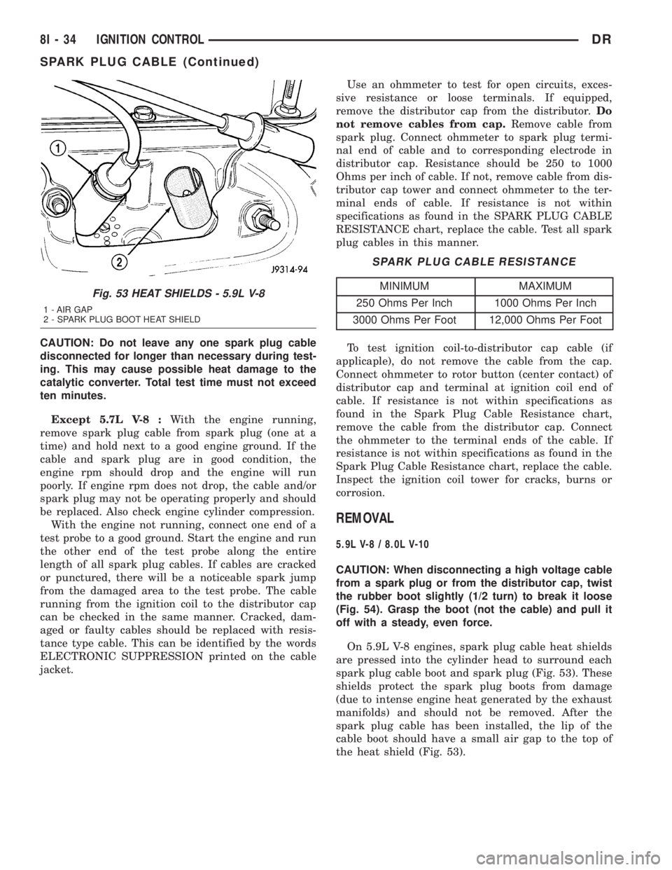
On 5.9L V-8 engines, spark plug cable heat shields
are pressed into the cylinder head to surround each
spark plug cable boot and spark plug (Fig. 53). These
shields protect the spark plug boots from damage
(due to intense engine heat generated by the exhaust
manifolds) and should not be removed. After the
spark plug cable has been installed, the lip of the
cable boot should have a small air gap to the top of
the heat shield (Fig. 53).
Fig. 53 HEAT SHIELDS - 5.9L V-8
1 - AIR GAP
2 - SPARK PLUG BOOT HEAT SHIELD
8I - 34 IGNITION CONTROLDR
SPARK PLUG CABLE (Continued)
Page 1700 of 2895
(2) Remove fuel pump relay from Power Distribu-
tion Center (PDC). For location of relay, refer to label
on underside of PDC cover.
(3) Start and run engine until it stalls.
(4) Attempt restarting engine until it will no
longer run.
(5) Turn ignition key to OFF position.
CAUTION: Steps 1, 2, 3 and 4 must be performed to
relieve high pressure fuel from within fuel rail. Do
not attempt to use following steps to relieve this
pressure as excessive fuel will be forced into a cyl-
inder chamber.
(6) Unplug connector from any fuel injector.
(7) Attach one end of a jumper wire with alligator
clips (18 gauge or smaller) to either injector terminal.
(8) Connect other end of jumper wire to positive
side of battery.(9) Connect one end of a second jumper wire to
remaining injector terminal.
CAUTION: Powering an injector for more than a few
seconds will permanently damage the injector.
(10) Momentarily touch other end of jumper wire
to negative terminal of battery for no more than a
few seconds.
(11) Place a rag or towel below fuel line quick-con-
nect fitting at fuel rail.
(12) Disconnect quick-connect fitting at fuel rail.
Refer to Quick-Connect Fittings.
(13) Return fuel pump relay to PDC.
(14) One or more Diagnostic Trouble Codes (DTC's)
may have been stored in PCM memory due to fuel
pump relay removal. The DRBtscan tool must be
used to erase a DTC.
SPECIFICATIONS
FUEL SYSTEM PRESSURE
339 kPa +/- 34 kPa (49.2 psi +/- 2 psi).
TORQUE - FUEL SYSTEM
DESCRIPTION N-m Ft. Lbs. In. Lbs.
Accelerator Pedal Bracket
Mounting12 - 105
Accelerator Pedal Position
Sensor Bracket-to-Battery
Tray Bolts3-30
Crankshaft Position
Sensor - 3.7L28 21 -
Crankshaft Position
Sensor - 4.7L28 21 -
Crankshaft Position
Sensor - 5.7L12 - 105 (+/-20)
Crankshaft Position
Sensor - 5.9L8-70
Crankshaft Position
Sensor - 8.0L8-70
Camshaft Position Sensor
- 3.7L12 - 106
Camshaft Position Sensor
- 4.7L12 - 106
Camshaft Position Sensor
- 5.7L12 9 105 (+/-) 20
Camshaft Position Sensor
- 8.0L6-50
DRFUEL DELIVERY - GAS 14 - 3
FUEL DELIVERY - GAS (Continued)
Page 2874 of 2895

JOINT - INSTALLATION, UPPER BALL.....2-33
JOINT - REMOVAL, LOWER BALL.....2-18,2-32
JOINT - REMOVAL, UPPER BALL.........2-33
JOINT-INNER - INSTALLATION, CV........3-16
JOINT-INNER - REMOVAL, CV............3-16
JOINT-OUTER - INSTALLATION, CV........3-13
JOINT-OUTER - REMOVAL, CV...........3-13
JOINTS - ASSEMBLY, SINGLE CARDAN
UNIVERSAL...........................3-9
JOINTS - DISASSEMBLY, SINGLE
CARDAN UNIVERSAL...................3-9
JOUNCE BUMPER - INSTALLATION.......2-40
JOUNCE BUMPER - REMOVAL...........2-40
JOURNAL CLEARANCE - STANDARD
PROCEDURE, CONNECTING ROD
BEARING AND CRANKSHAFT...........9-321
JUMP STARTING - STANDARD
PROCEDURE.........................0-13
JUNCTION BLOCK - INSTALLATION,
BRAKE..............................5-19
JUNCTION BLOCK - REMOVAL, BRAKE....5-19
KEY CYLINDER - INSTALLATION.........19-12
KEY CYLINDER - REMOVAL............19-12
KEY IMMOBILIZER MODULE -
DESCRIPTION, SENTRY................8E-13
KEY IMMOBILIZER MODULE -
INSTALLATION, SENTRY...............8E-15
KEY IMMOBILIZER MODULE -
OPERATION, SENTRY.................8E-13
KEY IMMOBILIZER MODULE - REMOVAL,
SENTRY............................8E-15
KEY IMMOBILIZER SYSTEM INDICATOR
LAMP - DESCRIPTION, SENTRY..........8Q-5
KEY IMMOBILIZER SYSTEM INDICATOR
LAMP - OPERATION, SENTRY...........8Q-5
KEY IMMOBILIZER SYSTEM
INITIALIZATION, STANDARD
PROCEDURE - SENTRY................8Q-3
KEY IMMOBILIZER SYSTEM (SKIS),
DESCRIPTION - SENTRY................8Q-1
KEY IMMOBILIZER SYSTEM
TRANSPONDER PROGRAMMING,
STANDARD PROCEDURE - SENTRY.......8Q-4
KEY LOCK CYLINDER - DIAGNOSIS AND
TESTING, IGNITION SWITCH............19-11
KEY-IN IGNITION SWITCH -
DESCRIPTION.......................19-11
KEYLESS ENTRY MODULE -
DESCRIPTION, REMOTE................8N-7
KEYLESS ENTRY MODULE - DIAGNOSIS
AND TESTING, REMOTE................8N-8
KEYLESS ENTRY MODULE -
INSTALLATION, REMOTE...............8N-8
KEYLESS ENTRY MODULE - OPERATION,
REMOTE............................8N-8
KEYLESS ENTRY MODULE - REMOVAL,
REMOTE............................8N-8
KEYLESS ENTRY TRANSMITTER -
DIAGNOSIS AND TESTING, REMOTE......8N-8
KEYLESS ENTRY TRANSMITTER -
SPECIFICATIONS, REMOTE.............8N-10
KNOCK SENSOR - DESCRIPTION.........8I-25
KNOCK SENSOR - INSTALLATION........8I-26
KNOCK SENSOR - OPERATION..........8I-25
KNOCK SENSOR - REMOVAL............8I-25
KNUCKLE - DESCRIPTION...............2-17
KNUCKLE - INSTALLATION..........2-18,2-34
KNUCKLE - OPERATION................2-17
KNUCKLE - REMOVAL..............2-17,2-34
LABEL - DESCRIPTION, VEHICLE SAFETY
CERTIFICATION.....................Intro.-1
LAMP - DESCRIPTION, DOME...........8L-24
LAMP - DESCRIPTION, READING........8L-26
LAMP - DESCRIPTION, SENTRY KEY
IMMOBILIZER SYSTEM INDICATOR.......8Q-5
LAMP - INSTALLATION, BACKUP.........8L-7
LAMP - INSTALLATION, BRAKE..........8L-8
LAMP - INSTALLATION, CAB CLEARANCE . 8L-10
LAMP - INSTALLATION, CENTER HIGH
MOUNTED STOP.....................8L-10
LAMP - INSTALLATION, DOME..........8L-24
LAMP - INSTALLATION, FOG............8L-11
LAMP - INSTALLATION, LICENSE PLATE
. . 8L-16
LAMP - INSTALLATION, PARK/TURN
SIGNAL
............................8L-21
LAMP - INSTALLATION, READING
........8L-26
LAMP - INSTALLATION, TAIL
...........8L-21
LAMP - INSTALLATION, TURN
..........8L-22LAMP - INSTALLATION, UNDERHOOD....8L-22
LAMP - OPERATION, DOME............8L-24
LAMP - OPERATION, READING..........8L-26
LAMP - OPERATION, SENTRY KEY
IMMOBILIZER SYSTEM INDICATOR.......8Q-5
LAMP - REMOVAL, BACKUP.............8L-7
LAMP - REMOVAL, BRAKE..............8L-8
LAMP - REMOVAL, CAB CLEARANCE.....8L-10
LAMP - REMOVAL, CENTER HIGH
MOUNTED STOP.....................8L-10
LAMP - REMOVAL, DOME..............8L-24
LAMP - REMOVAL, FOG...............8L-11
LAMP - REMOVAL, LICENSE PLATE......8L-16
LAMP - REMOVAL, PARK/TURN SIGNAL . . 8L-21
LAMP - REMOVAL, READING...........8L-26
LAMP - REMOVAL, TAIL...............8L-21
LAMP - REMOVAL, TURN..............8L-22
LAMP - REMOVAL, UNDERHOOD........8L-22
LAMP INDICATOR - DESCRIPTION,
CARGO.............................8J-20
LAMP INDICATOR - OPERATION, CARGO . . 8J-20
LAMP (MIL) - DESCRIPTION,
MALFUNCTION INDICATOR.............8J-30
LAMP (MIL) - OPERATION,
MALFUNCTION INDICATOR.............8J-30
LAMP OUT INDICATOR - DESCRIPTION . . . 8J-28
LAMP OUT INDICATOR - OPERATION.....8J-28
LAMP RELAY - DESCRIPTION, FOG........8L-11
LAMP RELAY - DESCRIPTION, PARK.....8L-19
LAMP RELAY - DIAGNOSIS AND
TESTING, FRONT FOG.................8L-12
LAMP RELAY - DIAGNOSIS AND
TESTING, PARK......................8L-20
LAMP RELAY - INSTALLATION, FOG......8L-13
LAMP RELAY - INSTALLATION, PARK.....8L-21
LAMP RELAY - OPERATION, FOG........8L-12
LAMP RELAY - OPERATION, PARK.......8L-19
LAMP RELAY - REMOVAL, FOG.........8L-13
LAMP RELAY - REMOVAL, PARK........8L-20
LAMP REPLACEMENT - STANDARD
PROCEDURE, MODULE................8M-3
LAMP REPLACEMENT - STANDARD
PROCEDURE, READING/COURTESY.......8M-3
LAMP SWITCH - DESCRIPTION, BACKUP . . . 8L-7
LAMP SWITCH - DESCRIPTION, BRAKE....8L-8
LAMP SWITCH - DIAGNOSIS AND
TESTING, BACKUP.....................8L-8
LAMP SWITCH - DIAGNOSIS AND
TESTING, BRAKE......................8L-9
LAMP SWITCH - INSTALLATION, BRAKE . . 8L-10
LAMP SWITCH - OPERATION, BACKUP....8L-8
LAMP SWITCH - OPERATION, BRAKE......8L-8
LAMP SWITCH - REMOVAL, BRAKE.......8L-9
LAMP UNIT - INSTALLATION, CENTER
HIGH MOUNTED STOP................8L-10
LAMP UNIT - INSTALLATION, LICENSE
PLATE .............................8L-16
LAMP UNIT - INSTALLATION, TAIL.......8L-21
LAMP UNIT - INSTALLATION,
UNDERHOOD........................8L-23
LAMP UNIT - REMOVAL, CENTER HIGH
MOUNTED STOP.....................8L-10
LAMP UNIT - REMOVAL, LICENSE PLATE . . 8L-16
LAMP UNIT - REMOVAL, TAIL...........8L-21
LAMP UNIT - REMOVAL, UNDERHOOD . . . 8L-22
LAMPS, SPECIFICATIONS - EXTERIOR.....8L-7
LAMPS/LIGHTING - EXTERIOR -
DESCRIPTION........................8L-2
LAMPS/LIGHTING - EXTERIOR -
DIAGNOSIS AND TESTING..............8L-3
LAMPS/LIGHTING - EXTERIOR -
OPERATION..........................8L-2
LAMP/SWITCH - INSTALLATION, GLOVE
BOX ...............................8L-25
LAMP/SWITCH - REMOVAL, GLOVE BOX . . 8L-25
LASH ADJUSTER - DIAGNOSIS AND
TESTING, HYDRAULIC.............9-124,9-31
LASH ADJUSTMENT AND VERIFICATION
- STANDARD PROCEDURE, VALVE.......9-308
LATCH - INSTALLATION.....23-16,23-23,23-32,
23-47
LATCH - INSTALLATION, GLOVE BOX
.....23-53
LATCH - INSTALLATION, UNDER SEAT
STORAGE BIN
.......................23-81
LATCH - REMOVAL
....23-16,23-23,23-32,23-47
LATCH - REMOVAL, GLOVE BOX
.........23-53
LATCH - REMOVAL, UNDER SEAT
STORAGE BIN
.......................23-81LATCH RELEASE CABLE/HANDLE
ASSEMBLY - INSTALLATION............23-47
LATCH RELEASE CABLE/HANDLE
ASSEMBLY - REMOVAL................23-47
LATCH STRIKER - INSTALLATION . . 23-17,23-24,
23-33
LATCH STRIKER - REMOVAL . 23-17,23-24,23-33
LATCH STRIKER / SECONDARY CATCH -
INSTALLATION.......................23-48
LATCH STRIKER / SECONDARY CATCH -
REMOVAL..........................23-48
LD & HD EXCEPT 4X4 HD -
INSTALLATION, ALL..................19-15
LD & HD EXCEPT 4X4 HD - REMOVAL,
ALL ...............................19-14
LEAD - DIAGNOSIS AND TESTING,
TIRE/VEHICLE........................22-8
LEAK - DIAGNOSIS AND TESTING,
CONVERTER HOUSING FLUID . . . 21-143,21-324,
21-495
LEAK - DIAGNOSIS AND TESTING,
ENGINE OIL................9-150,9-214,9-63
LEAK DETECTION ASSY - DESCRIPTION,
NATURAL VAC.......................25-23
LEAK DETECTION ASSY - INSTALLATION,
NATURAL VAC.......................25-24
LEAK DETECTION ASSY - OPERATION,
NATURAL VAC.......................25-23
LEAK DETECTION ASSY - REMOVAL,
NATURAL VAC.......................25-24
LEAK DETECTION PUMP - DESCRIPTION . . 25-13
LEAK DETECTION PUMP - INSTALLATION . 25-16
LEAK DETECTION PUMP - OPERATION.....25-14
LEAK DETECTION PUMP - REMOVAL.....25-16
LEAKAGE - DIAGNOSIS AND TESTING,
CYLINDER COMBUSTION PRESSURE....9-182,
9-231,9-359,9-8,9-92
LEAKAGE - DIAGNOSIS AND TESTING,
INTAKE MANIFOLD....9-157,9-219,9-274,9-401
LEAKAGE - DIAGNOSIS AND TESTING,
PUMP.............................19-39
LEAKS - DIAGNOSIS AND TESTING,
CHARGE AIR COOLER SYSTEM.........11-15
LEAKS - DIAGNOSIS AND TESTING,
COOLING SYSTEM - TESTING.............7-5
LEAKS - DIAGNOSIS AND TESTING,
ENGINE OIL....................9-269,9-394
LEAKS - DIAGNOSIS AND TESTING,
HIGH-PRESSURE FUEL LINE............14-69
LEAKS - DIAGNOSIS AND TESTING,
INTAKE MANIFOLD....................9-71
LEAKS - DIAGNOSIS AND TESTING,
REAR SEAL AREA...........9-135,9-204,9-64
LEAKS - DIAGNOSIS AND TESTING,
REFRIGERANT SYSTEM...............24-51
LEAKS - DIAGNOSIS AND TESTING,
WATER .............................23-1
LEAKS - STANDARD PROCEDURE,
REPAIRING.........................22-10
LEARN - STANDARD PROCEDURE,
DRIVE.............................8E-21
LEARN - STANDARD PROCEDURE, TCM
QUICK.............................8E-21
LEFT - DESCRIPTION, CAMSHAFT(S).....9-113
LEFT - INSTALLATION..................2-34
LEFT - INSTALLATION, CAMSHAFT(S)....9-114
LEFT - INSTALLATION, CYLINDER HEAD . . . 9-23
LEFT - REMOVAL......................2-34
LEFT - REMOVAL, CAMSHAFT(S)........9-113
LEFT - REMOVAL, CYLINDER HEAD.......9-21
LEFT CYLINDER HEAD - INSTALLATION . . . 9-110
LEFT CYLINDER HEAD - REMOVAL.......9-106
LEFT OUTBOARD - INSTALLATION,
CENTER............................8O-45
LEFT OUTBOARD - REMOVAL, CENTER . . . 8O-43
LEFT REAR CABLE - INSTALLATION.......5-33
LEFT REAR CABLE - REMOVAL...........5-32
LEFT SIDE - INSTALLATION............9-122
LEFT SIDE - REMOVAL
................9-121
LENS REPLACEMENT - STANDARD
PROCEDURE, MODULE
................8M-3
LEVEL - DIAGNOSIS AND TESTING,
EFFECTS OF INCORRECT FLUID
. . 21-201,21-381,
21-541
LEVEL - STANDARD PROCEDURE,
BRAKE FLUID
........................5-18
LEVEL - STANDARD PROCEDURE,
ENGINE OIL
.........................9-341
DRINDEX 19
Description Group-Page Description Group-Page Description Group-Page
Page 2887 of 2895

SIDE - REMOVAL, LEFT................9-121
SIDE - REMOVAL, RIGHT..............9-121
SIDE BEZEL - INSTALLATION,
INSTRUMENT PANEL DRIVER...........23-59
SIDE BEZEL - REMOVAL, INSTRUMENT
PANEL DRIVER......................23-58
SIDE CURTAIN AIRBAG - DESCRIPTION . . . 8O-51
SIDE CURTAIN AIRBAG - INSTALLATION . . 8O-53
SIDE CURTAIN AIRBAG - OPERATION....8O-51
SIDE CURTAIN AIRBAG - REMOVAL......8O-52
SIDE IMPACT AIRBAG CONTROL
MODULE - DESCRIPTION..............8O-53
SIDE IMPACT AIRBAG CONTROL
MODULE - OPERATION................8O-54
SIDE MOLDINGS - INSTALLATION, BODY . . 23-36
SIDE MOLDINGS - REMOVAL, BODY.....23-36
SIDE VIEW MIRROR - INSTALLATION.....23-41
SIDE VIEW MIRROR - REMOVAL........23-41
SIDE VIEW MIRROR FLAG -
INSTALLATION.......................23-27
SIDE VIEW MIRROR FLAG - REMOVAL . . . 23-27
SIDE VIEW MIRROR GLASS -
INSTALLATION.......................23-44
SIDE VIEW MIRROR GLASS - REMOVAL . . 23-42
SIDEVIEW MIRROR - REMOVAL.........8N-13
SIGNAL INDICATOR - DESCRIPTION,
TURN..............................8J-39
SIGNAL INDICATOR - OPERATION, TURN . . 8J-39
SIGNAL LAMP - INSTALLATION,
PARK/TURN.........................8L-21
SIGNAL LAMP - REMOVAL, PARK/TURN . . 8L-21
SIGNAL SYSTEM - DESCRIPTION, TURN . . 8L-17
SIGNAL SYSTEM - OPERATION, TURN....8L-18
SILL TRIM COVER - INSTALLATION,
REAR DOOR........................23-72
SILL TRIM COVER - REMOVAL, REAR
DOOR.............................23-72
SINGLE CARDAN UNIVERSAL JOINTS -
ASSEMBLY...........................3-9
SINGLE CARDAN UNIVERSAL JOINTS -
DISASSEMBLY.........................3-9
SIZE, SPARE WHEEL WITH MATCHING
TIRE - DESCRIPTION, FULL............22-15
SKID PLATE - INSTALLATION, FRONT.....13-24
SKID PLATE - INSTALLATION, TRANSFER
CASE..............................13-26
SKID PLATE - REMOVAL, FRONT........13-24
SKID PLATE - REMOVAL, TRANSFER
CASE..............................13-26
SLEEVE - INSTALLATION, HEADREST.....23-82
SLEEVE - REMOVAL, HEADREST........23-82
SMOKE DIAGNOSIS CHARTS -
DIAGNOSIS AND TESTING.............9-285
SOLENOID - DESCRIPTION......21-253,21-431
SOLENOID - DESCRIPTION, EVAP/PURGE . 25-12
SOLENOID - INSTALLATION, EVAP/
PURGE.............................25-13
SOLENOID - OPERATION........21-254,21-431
SOLENOID - OPERATION, EVAP/PURGE . . . 25-12
SOLENOID - REMOVAL, EVAP/PURGE.....25-13
SOLENOID SWITCH VALVE -
DESCRIPTION......................21-574
SOLENOID SWITCH VALVE - OPERATION . 21-574
SOLENOIDS - DESCRIPTION...........21-574
SOLENOIDS - OPERATION.............21-575
SOLENOID/TRS ASSEMBLY -
DESCRIPTION, TRANSMISSION........21-582
SOLENOID/TRS ASSEMBLY -
INSTALLATION, TRANSMISSION........21-583
SOLENOID/TRS ASSEMBLY -
OPERATION, TRANSMISSION..........21-582
SOLENOID/TRS ASSEMBLY - REMOVAL,
TRANSMISSION.....................21-583
SOLID LIFTERS/TAPPETS - CLEANING....9-328
SOLID LIFTERS/TAPPETS - INSPECTION . . 9-328
SOLID LIFTERS/TAPPETS -
INSTALLATION.......................9-328
SOLID LIFTERS/TAPPETS - REMOVAL....9-327
SPARE / TEMPORARY TIRE -
DESCRIPTION.......................22-15
SPARE TIRE / TEMPORARY -
DESCRIPTION........................22-5
SPARE WHEEL WITH MATCHING TIRE -
DESCRIPTION, FULL SIZE
..............22-15
SPARK PLUG - DESCRIPTION
...........8I-27
SPARK PLUG - REMOVAL
..............8I-30
SPARK PLUG CABLE - DESCRIPTION
.....8I-33
SPARK PLUG CABLE - INSTALLATION
.....8I-35SPARK PLUG CABLE - OPERATION.......8I-33
SPARK PLUG CABLE - REMOVAL........8I-34
SPARK PLUG CABLE ORDER, 8.0L V-10
ENGINE..............................8I-5
SPARK PLUG CABLE RESISTANCE,
SPECIFICATIONS......................8I-5
SPARK PLUG CABLES - DIAGNOSIS AND
TESTING............................8I-33
SPARK PLUG CONDITIONS - DIAGNOSIS
AND TESTING........................8I-27
SPARK PLUGS, SPECIFICATIONS..........8I-5
SPEAKER - DESCRIPTION..............8A-12
SPEAKER - DIAGNOSIS AND TESTING....8A-13
SPEAKER - INSTALLATION.............8A-15
SPEAKER - OPERATION...............8A-12
SPEAKER - REMOVAL.................8A-13
SPECIFICATIONS......................7-20
SPEED CONTROL - DESCRIPTION........8P-1
SPEED CONTROL - OPERATION..........8P-2
SPEED CONTROL - TORQUE.............8P-3
SPEED SENSOR - DESCRIPTION . . 21-254,21-431
SPEED SENSOR - DESCRIPTION, FRONT
WHEEL.............................5-41
SPEED SENSOR - DESCRIPTION, INPUT . 21-558
SPEED SENSOR - DESCRIPTION,
OUTPUT...........................21-567
SPEED SENSOR - DIAGNOSIS AND
TESTING, REAR WHEEL................5-43
SPEED SENSOR - INSTALLATION, FRONT
WHEEL.............................5-42
SPEED SENSOR - INSTALLATION, INPUT . 21-559
SPEED SENSOR - INSTALLATION,
OUTPUT...........................21-567
SPEED SENSOR - INSTALLATION, REAR
WHEEL.............................5-43
SPEED SENSOR - OPERATION . . . 21-254,21-431
SPEED SENSOR - OPERATION, FRONT
WHEEL.............................5-41
SPEED SENSOR - OPERATION, INPUT . . . 21-558
SPEED SENSOR - OPERATION, OUTPUT . . 21-567
SPEED SENSOR - REMOVAL, FRONT
WHEEL.............................5-41
SPEED SENSOR - REMOVAL, INPUT.....21-559
SPEED SENSOR - REMOVAL, OUTPUT . . . 21-567
SPEED SENSOR - REMOVAL, REAR
WHEEL.............................5-42
SPEEDOMETER - DESCRIPTION.........8J-36
SPEEDOMETER - OPERATION...........8J-36
SPEEDS - DESCRIPTION, TIRE
PRESSURE FOR HIGH..................22-6
SPLASH SHIELD - INSTALLATION,
FRONT WHEELHOUSE.................23-41
SPLASH SHIELD - INSTALLATION, REAR
WHEELHOUSE.......................23-41
SPLASH SHIELD - REMOVAL, FRONT
WHEELHOUSE.......................23-40
SPLASH SHIELD - REMOVAL, REAR
WHEELHOUSE.......................23-41
SPLICE INFORMATION - DESCRIPTION,
CONNECTOR, GROUND..............8W-01-7
SPLICING - STANDARD PROCEDURE,
WIRE...........................8W-01-15
SPRING - DESCRIPTION................2-41
SPRING - INSTALLATION.......2-22,2-36,2-41
SPRING - OPERATION..................2-41
SPRING - REMOVAL...........2-21,2-36,2-41
SPRING AND SHOCK - DIAGNOSIS AND
TESTING............................2-38
SPRING BUMPERS (3500) -
INSTALLATION, AUXILIARY..............2-40
SPRING BUMPERS (3500) - REMOVAL,
AUXILIARY..........................2-40
SPRING TIP INSERTS - INSTALLATION....2-42
SPRING TIP INSERTS - REMOVAL........2-41
SPRINGS - DESCRIPTION, VALVE . . . 9-125,9-31,
9-36
SPRINGS - INSTALLATION, VALVE . . 9-126,9-199,
9-31,9-37
SPRINGS - INSTALLATION, VALVES AND
VALVE
.............................9-379
SPRINGS - REMOVAL, VALVE
. 9-125,9-199,9-31,
9-37
SPRINGS - REMOVAL, VALVES AND
VALVE
.............................9-377
SPRINGS - STANDARD PROCEDURE,
VALVES, GUIDES
................9-246,9-305
SPRINGS AND SEALS - REMOVAL,
VALVE
.............................9-308SPROCKETS - INSPECTION, TIMING
BELT/CHAIN.....................9-171,9-83
SPROCKETS - INSTALLATION, TIMING
BELT/CHAIN...........9-172,9-279,9-406,9-84
SPROCKETS - INSTALLATION,
TIMING/CHAIN.......................9-222
SPROCKETS - REMOVAL, TIMING
BELT/CHAIN...........9-169,9-279,9-405,9-81
SPROCKETS - REMOVAL, TIMING/CHAIN . . 9-221
SQUEAK & RATTLE - STANDARD
PROCEDURE, BUZZ...................23-11
STABILIZER BAR - DESCRIPTION.........2-24
STABILIZER BAR - INSTALLATION....2-24,2-37
STABILIZER BAR - OPERATION...........2-24
STABILIZER BAR - REMOVAL........2-24,2-37
STAKING - STANDARD PROCEDURE,
HEAT ...............................23-3
STANDARD CAB - INSTALLATION........8O-31
STANDARD CAB - REMOVAL...........8O-28
STARTER MOTOR - DIAGNOSIS AND
TESTING...........................8F-34
STARTER MOTOR - INSTALLATION.......8F-37
STARTER MOTOR - REMOVAL..........8F-34
STARTER MOTOR RELAY - DESCRIPTION . 8F-38
STARTER MOTOR RELAY -
INSTALLATION.......................8F-39
STARTER MOTOR RELAY - OPERATION . . . 8F-38
STARTER MOTOR RELAY - REMOVAL.....8F-39
STARTER RELAY - DIAGNOSIS AND
TESTING.............................8F-38
STARTING - DESCRIPTION.............8F-28
STARTING - OPERATION...............8F-28
STARTING - STANDARD PROCEDURE,
JUMP...............................0-13
STARTING SYSTEM - DIAGNOSIS AND
TESTING...........................8F-29
STARTING SYSTEM - SPECIFICATIONS,
TORQUE............................8F-34
STARTING SYSTEM, SPECIFICATIONS.....8F-33
STATE DISPLAY TEST MODE -
DESCRIPTION........................25-1
STEERING - DESCRIPTION..............19-1
STEERING - OPERATION................19-1
STEERING COLUMN - DIAGNOSIS AND
TESTING............................19-7
STEERING COLUMN OPENING COVER -
INSTALLATION.......................23-61
STEERING COLUMN OPENING COVER -
REMOVAL..........................23-61
STEERING COLUMN OPENING SUPPORT
BRACKET - INSTALLATION.............23-62
STEERING COLUMN OPENING SUPPORT
BRACKET - REMOVAL.................23-61
STEERING COUPLING - INSTALLATION,
UPPER.............................19-14
STEERING COUPLING - REMOVAL,
UPPER.............................19-13
STEERING FLOW AND PRESSURE -
DIAGNOSIS AND TESTING, POWER.......19-4
STEERING FLUID - DESCRIPTION,
POWER..............................0-3
STEERING FLUID LEVEL CHECKING -
STANDARD PROCEDURE, POWER.......19-42
STEERING GEAR INPUT SHAFT SEAL -
INSTALLATION.......................19-28
STEERING GEAR INPUT SHAFT SEAL -
REMOVAL..........................19-25
STEERING GEAR, SPECIAL TOOLS -
POWER............................19-22
STEERING GEAR, SPECIFICATIONS -
POWER............................19-21
STEERING LINKAGE, SPECIAL TOOLS....19-35
STEERING PRESSURE SWITCH -
DESCRIPTION, POWER................19-45
STEERING PRESSURE SWITCH -
OPERATION, POWER..................19-45
STEERING PUMP - INITIAL OPERATION -
STANDARD PROCEDURE, POWER.......19-39
STEERING, SPECIAL TOOLS.............19-5
STEERING SYSTEM - DIAGNOSIS AND
TESTING, POWER.....................19-2
STEERING SYSTEM - STANDARD
PROCEDURE, FLUSHING POWER
........19-39
STEERING WHEEL - INSTALLATION
......19-15
STEERING WHEEL - REMOVAL
..........19-15
STEM SEAL - INSTALLATION, VALVE
.....9-378
STEM SEALS - DESCRIPTION, VALVE
....9-126,
9-198
32 INDEXDR
Description Group-Page Description Group-Page Description Group-Page