key battery DODGE RAM 2003 Service Repair Manual
[x] Cancel search | Manufacturer: DODGE, Model Year: 2003, Model line: RAM, Model: DODGE RAM 2003Pages: 2895, PDF Size: 83.15 MB
Page 371 of 2895
INSTALLATION
(1) Install antenna cable to radio.
(2) Connect electrical harness connector to radio.
(3) Install radio to instrument panel.
(4) Install instrument panel center bezel (Refer to
23 - BODY/INSTRUMENT PANEL/INSTRUMENT
PANEL CENTER BEZEL - INSTALLATION).
(5) Connect battery negative cable.
RADIO NOISE SUPPRESSION
GROUND STRAP
DESCRIPTION
Radio noise suppression devices are factory-in-
stalled standard equipment on this vehicle. Radio
Frequency Interference (RFI) and ElectroMagnetic
Interference (EMI) can be produced by any on-board
or external source of electromagnetic energy. These
electromagnetic energy sources can radiate electro-
magnetic signals through the air, or conduct them
through the vehicle electrical system.
When the audio system converts RFI or EMI to an
audible acoustic wave form, it is referred to as radio
noise. This undesirable radio noise is generally man-
ifested in the form of ªbuzzing,º ªhissing,º ªpopping,º
ªclicking,º ªcrackling,º and/or ªwhirringº sounds. In
most cases, RFI and EMI radio noise can be sup-
pressed using a combination of vehicle and compo-
nent grounding, filtering and shielding techniques.
This vehicle is equipped with factory-installed radio
noise suppression devices that were designed to min-
imize exposure to typical sources of RFI and EMI;
thereby, minimizing radio noise complaints.Factory-installed radio noise suppression is accom-
plished primarily through circuitry or devices that
are integral to the factory-installed radios, audio
power amplifiers and other on-board electrical com-
ponents such as generators, wiper motors, blower
motors, and fuel pumps that have been found to be
potential sources of RFI or EMI. External radio noise
suppression devices that are used on this vehicle to
control RFI or EMI, and can be serviced, include the
following:
²Engine-to-body ground strap- This length of
braided ground strap has an eyelet terminal connec-
tor crimped to each end. One end is secured to the
engine cylinder head(s). The other is secured to the
plenum at the exhaust heat shield forward/outer
attaching stud.
²Resistor-type spark plugs- This type of spark
plug has an internal resistor connected in series
between the spark plug terminal and the center elec-
trode to help reduce the production of electromag-
netic radiation that can result in radio noise.
OPERATION
There are two common strategies that can be used
to suppress Radio Frequency Interference (RFI) and
ElectroMagnetic Interference (EMI) radio noise. The
first suppression strategy involves preventing the
production of RFI and EMI electromagnetic signals
at their sources. The second suppression strategy
involves preventing the reception of RFI and EMI
electromagnetic signals by the audio system compo-
nents.
The use of braided ground straps in key locations
is part of the RFI and EMI prevention strategy.
These ground straps ensure adequate ground paths,
particularly for high current components such as
many of those found in the starting, charging, igni-
tion, engine control and transmission control sys-
tems. An insufficient ground path for any of these
high current components may result in radio noise
caused by induced voltages created as the high cur-
rent seeks alternative ground paths through compo-
nents or circuits intended for use by, or in close
proximity to the audio system components or circuits.
Preventing the reception of RFI and EMI is accom-
plished by ensuring that the audio system compo-
nents are correctly installed in the vehicle. Loose,
corroded or improperly soldered wire harness connec-
tions, improperly routed wiring and inadequate audio
system component grounding can all contribute to
the reception of RFI and EMI. A properly grounded
antenna body and radio chassis, as well as a shielded
antenna coaxial cable with clean and tight connec-
tions will each help reduce the potential for reception
of RFI and EMI.
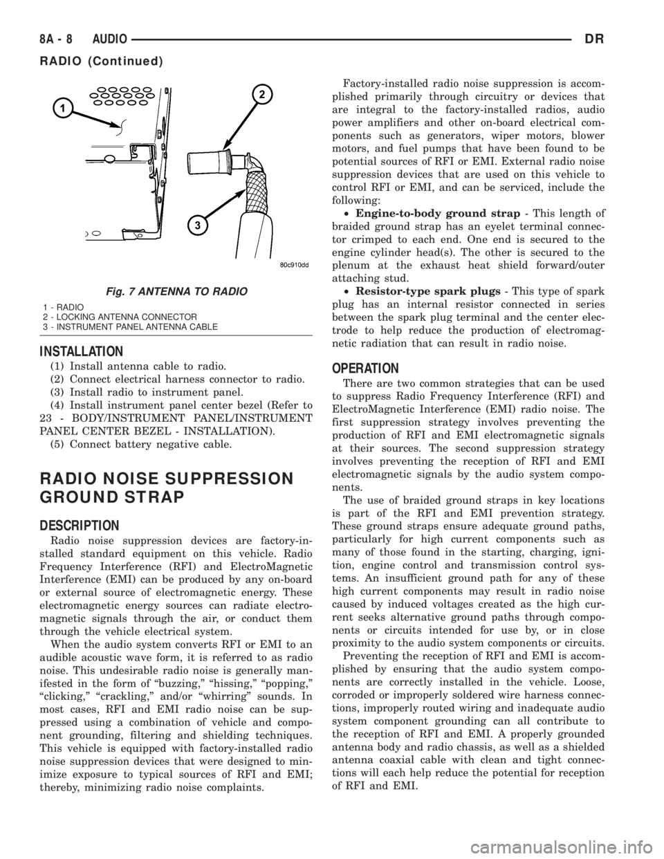
Fig. 7 ANTENNA TO RADIO
1 - RADIO
2 - LOCKING ANTENNA CONNECTOR
3 - INSTRUMENT PANEL ANTENNA CABLE
8A - 8 AUDIODR
RADIO (Continued)
Page 380 of 2895
CHIME/BUZZER
TABLE OF CONTENTS
page page
CHIME/BUZZER
DESCRIPTION..........................1
OPERATION............................1DIAGNOSIS AND TESTING - CHIME
CONDITIONS..........................2
CHIME/BUZZER
DESCRIPTION
The chime module is located within the instrument
cluster and is not serviceable. The chime system pro-
vides the driver with warning chimes for:
²Air Bag
²Seat Belt
²Low Fuel
²Door Ajar
²Low Wash
²Park Brake
²Over Speed
²Turn Signal On
²Key-In Ignition
²Exterior Lamps ON
²Warning Lamp Announcement
²Transmission Over Temperature
OPERATION
FASTEN SEAT BELT
The seat belt reminder system uses both visual
and audible signals. The Instrument Cluster moni-
tors the driver seat belt buckle switch. When the
ignition switch transitions from OFF to RUN and the
driver seat belt has not been buckled, the Instrument
Cluster will illuminate the seat belt indicator lamp
and sound the chime. The system will always illumi-
nate the seat belt reminder lamp for four to eight
seconds when the ignition switch is turned to the ON
position. The CHIME will sound during the same
time interval if the driver's seat belt is not fastened.
The warning lamp will remain illuminated as long as
the seat belt remains unbuckled, and the ignition
switch is in the RUN position. Passenger seat belts
are not connected to the system.
HEADLAMPS REMINDER
The Instrument Cluster monitors the multiplex
headlamp switch. The headlamp audible warning will
alert the driver that the exterior lamps have been
left on. If the ignition switch is left off, the driver's
door open, and the headlamp switch is in the parklamp or headlamp position, the chime will sound
until the headlamp switch is turned off, the door is
closed or the battery protection time out expires.
KEY IN IGNITION REMINDER
The Instrument Cluster monitors the ignition
switch. The chime will activate if the drivers door is
opened and the key is in the ignition switch, with the
ignition switch in either the OFF, LOCK, or the
accessory (ACC) position. The chime will continue
until the key is removed from the ignition switch or
the door is closed.
DOOR AJAR CHIME
The Instrument Cluster monitors the door ajar
switches. A chime will sound once when the door is
opened, the ignition is in RUN position and vehicle
speed is present.
TURN SIGNAL ON
The Instrument Cluster monitors the multiplex
multifunction switch. The instrument cluster shall
remind the driver that either turn signal has been
left on by a continuous chime after the turn signal
indicator is left ON for 1.0 miles and the vehicle
speed is 15 mph or greater.
LOW FUEL REMINDER
When the fuel level drops to approximately 1/8
tank, the fuel symbol will light and a single chime
will sound. The light will remain on until fuel is
added.
OVER SPEED
During any ignition ON, the Instrument Cluster
maintains the most recently received speed. If the
vehicle speed exceeds a preprogramed limit set in the
instrument cluster it will activate a single chime.
WARNING LAMP ANNOUNCEMENT
The Instrument Cluster monitors critical engine
and transmission system parameters. If any of the
systems are out of their operating parameters, the
instrument cluster will illuminate a lamp and acti-
vate and audible chime.
DRCHIME/BUZZER 8B - 1
Page 386 of 2895
To avoid possible voltage spike damage to either
the Engine Control Module ECM, ignition key must
be off, and negative battery cables must be discon-
nected before unplugging ECM connectors.
(2) Disconnect both negative battery cables at both
batteries.
(3) Remove the 50±way and 60±way connector
bolts at the ECM. Note: Tthe connector bolt is a
female allen head. As bolt is being removed, very car-
fully remove connectors from the ECM.
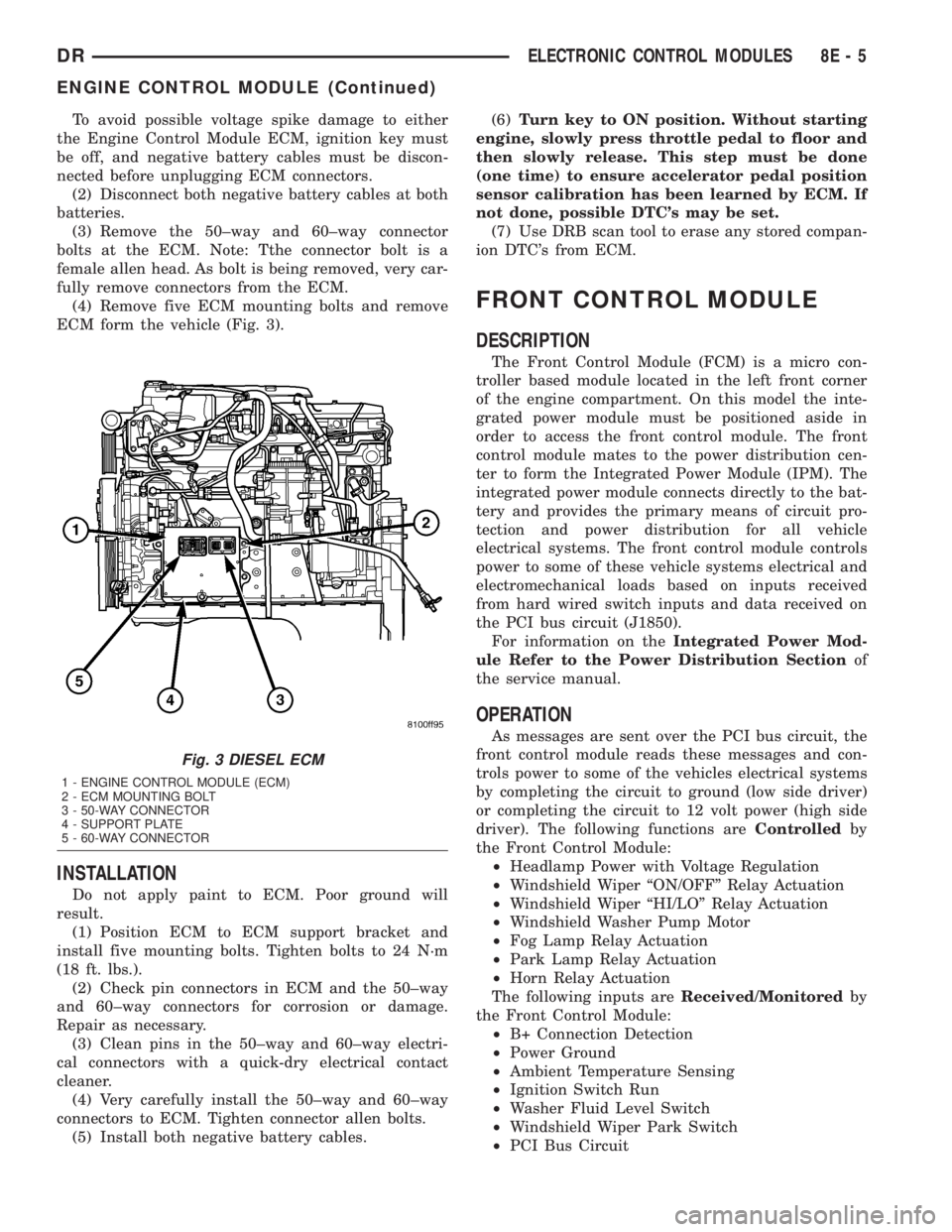
(4) Remove five ECM mounting bolts and remove
ECM form the vehicle (Fig. 3).
INSTALLATION
Do not apply paint to ECM. Poor ground will
result.
(1) Position ECM to ECM support bracket and
install five mounting bolts. Tighten bolts to 24 N´m
(18 ft. lbs.).
(2) Check pin connectors in ECM and the 50±way
and 60±way connectors for corrosion or damage.
Repair as necessary.
(3) Clean pins in the 50±way and 60±way electri-
cal connectors with a quick-dry electrical contact
cleaner.
(4) Very carefully install the 50±way and 60±way
connectors to ECM. Tighten connector allen bolts.
(5) Install both negative battery cables.(6)Turn key to ON position. Without starting
engine, slowly press throttle pedal to floor and
then slowly release. This step must be done
(one time) to ensure accelerator pedal position
sensor calibration has been learned by ECM. If
not done, possible DTC's may be set.
(7) Use DRB scan tool to erase any stored compan-
ion DTC's from ECM.
FRONT CONTROL MODULE
DESCRIPTION
The Front Control Module (FCM) is a micro con-
troller based module located in the left front corner
of the engine compartment. On this model the inte-
grated power module must be positioned aside in
order to access the front control module. The front
control module mates to the power distribution cen-
ter to form the Integrated Power Module (IPM). The
integrated power module connects directly to the bat-
tery and provides the primary means of circuit pro-
tection and power distribution for all vehicle
electrical systems. The front control module controls
power to some of these vehicle systems electrical and
electromechanical loads based on inputs received
from hard wired switch inputs and data received on
the PCI bus circuit (J1850).
For information on theIntegrated Power Mod-
ule Refer to the Power Distribution Sectionof
the service manual.
OPERATION
As messages are sent over the PCI bus circuit, the
front control module reads these messages and con-
trols power to some of the vehicles electrical systems
by completing the circuit to ground (low side driver)
or completing the circuit to 12 volt power (high side
driver). The following functions areControlledby
the Front Control Module:
²Headlamp Power with Voltage Regulation
²Windshield Wiper ªON/OFFº Relay Actuation
²Windshield Wiper ªHI/LOº Relay Actuation
²Windshield Washer Pump Motor
²Fog Lamp Relay Actuation
²Park Lamp Relay Actuation
²Horn Relay Actuation
The following inputs areReceived/Monitoredby
the Front Control Module:
²B+ Connection Detection
²Power Ground
²Ambient Temperature Sensing
²Ignition Switch Run
²Washer Fluid Level Switch
²Windshield Wiper Park Switch
²PCI Bus Circuit
Fig. 3 DIESEL ECM
1 - ENGINE CONTROL MODULE (ECM)
2 - ECM MOUNTING BOLT
3 - 50-WAY CONNECTOR
4 - SUPPORT PLATE
5 - 60-WAY CONNECTOR
DRELECTRONIC CONTROL MODULES 8E - 5
ENGINE CONTROL MODULE (Continued)
Page 393 of 2895
²supplies a reference voltage for the Throttle
Position Sensor (TPS) sensor.
Secondary 5±volt supply:
²supplies the required 5 volt power source to the
oil pressure sensor.
²supplies the required 5 volt power source for the
Vehicle Speed Sensor (VSS) (if equipped).
²supplies the 5 volt power source to the transmis-
sion pressure sensor (certain automatic transmis-
sions).
OPERATION - IGNITION CIRCUIT SENSE
The ignition circuit sense input tells the PCM the
ignition switch has energized the ignition circuit.
Battery voltage is also supplied to the PCM
through the ignition switch when the ignition is in
the RUN or START position. This is referred to as
the9ignition sense9circuit and is used to9wake up9
the PCM. Voltage on the ignition input can be as low
as 6 volts and the PCM will still function. Voltage is
supplied to this circuit to power the PCM's 8-volt reg-
ulator and to allow the PCM to perform fuel, ignition
and emissions control functions.
REMOVAL
USE THE DRB SCAN TOOL TO REPROGRAM
THE NEW POWERTRAIN CONTROL MODULE
(PCM) WITH THE VEHICLES ORIGINAL IDEN-
TIFICATION NUMBER (VIN) AND THE VEHI-
CLES ORIGINAL MILEAGE. IF THIS STEP IS
NOT DONE, A DIAGNOSTIC TROUBLE CODE
(DTC) MAY BE SET.
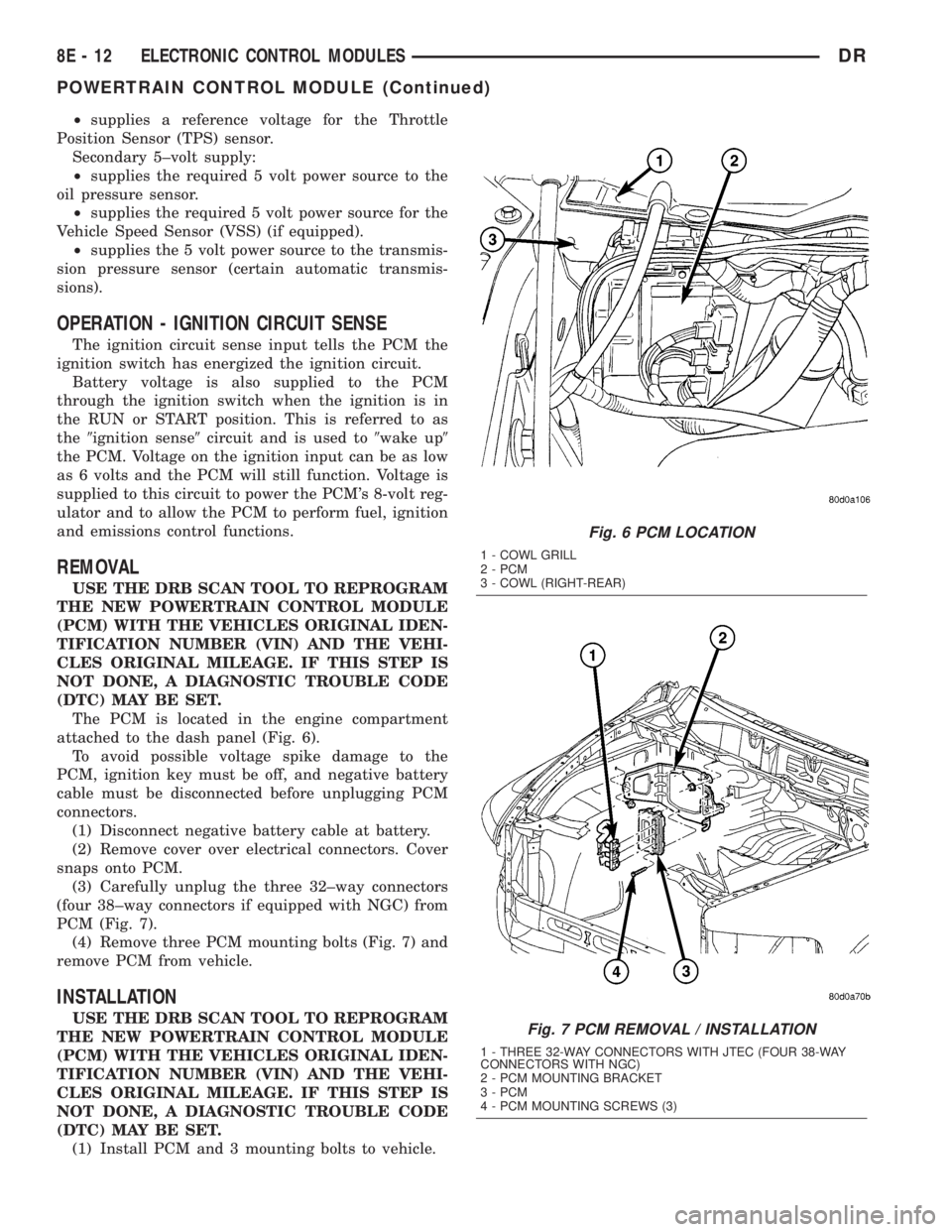
The PCM is located in the engine compartment
attached to the dash panel (Fig. 6).
To avoid possible voltage spike damage to the
PCM, ignition key must be off, and negative battery
cable must be disconnected before unplugging PCM
connectors.
(1) Disconnect negative battery cable at battery.
(2) Remove cover over electrical connectors. Cover
snaps onto PCM.
(3) Carefully unplug the three 32±way connectors
(four 38±way connectors if equipped with NGC) from
PCM (Fig. 7).
(4) Remove three PCM mounting bolts (Fig. 7) and
remove PCM from vehicle.
INSTALLATION
USE THE DRB SCAN TOOL TO REPROGRAM
THE NEW POWERTRAIN CONTROL MODULE
(PCM) WITH THE VEHICLES ORIGINAL IDEN-
TIFICATION NUMBER (VIN) AND THE VEHI-
CLES ORIGINAL MILEAGE. IF THIS STEP IS
NOT DONE, A DIAGNOSTIC TROUBLE CODE
(DTC) MAY BE SET.
(1) Install PCM and 3 mounting bolts to vehicle.
Fig. 6 PCM LOCATION
1 - COWL GRILL
2 - PCM
3 - COWL (RIGHT-REAR)
Fig. 7 PCM REMOVAL / INSTALLATION
1 - THREE 32-WAY CONNECTORS WITH JTEC (FOUR 38-WAY
CONNECTORS WITH NGC)
2 - PCM MOUNTING BRACKET
3 - PCM
4 - PCM MOUNTING SCREWS (3)
8E - 12 ELECTRONIC CONTROL MODULESDR
POWERTRAIN CONTROL MODULE (Continued)
Page 394 of 2895
(2) Tighten bolts. Refer to torque specifications.
(3) Check pin connectors in the PCM and the three
32±way connectors (four 38±way connectors if
equipped with NGC) for corrosion or damage. Also,
the pin heights in connectors should all be same.
Repair as necessary before installing connectors.
(4) Install three 32±way connectors (four 38±way
connectors if equipped with NGC).
(5) Install cover over electrical connectors. Cover
snaps onto PCM.
(6) Install negative battery cable.
(7) Use the DRB scan tool to reprogram new PCM
with vehicles original Vehicle Identification Number
(VIN) and original vehicle mileage.
SENTRY KEY IMMOBILIZER
MODULE
DESCRIPTION
The Sentry Key Immobilizer Module (SKIM) con-
tains a Radio Frequency (RF) transceiver and a cen-
tral processing unit, which includes the Sentry Key
Immobilizer System (SKIS) program logic. The SKIS
programming enables the SKIM to program and
retain in memory the codes of at least two, but no
more than eight electronically coded Sentry Key
transponders. The SKIS programming also enables
the SKIM to communicate over the Programmable
Communication Interface (PCI) bus network with the
Powertrain Control Module (PCM), and/or the
DRBIIItscan tool.
OPERATION
The SKIM transmits and receives RF signals
through a tuned antenna enclosed within a molded
plastic ring that is integral to the SKIM housing.
When the SKIM is properly installed on the steering
column, the antenna ring is oriented around the igni-
tion lock cylinder housing. This antenna ring must be
located within eight millimeters (0.31 inches) of the
Sentry Key in order to ensure proper RF communica-
tion between the SKIM and the Sentry Key tran-
sponder.
For added system security, each SKIM is pro-
grammed with a unique ªSecret Keyº code and a
security code. The SKIM keeps the ªSecret Keyº code
in memory. The SKIM also sends the ªSecret Keyº
code to each of the programmed Sentry Key tran-
sponders. The security code is used by the assembly
plant to access the SKIS for initialization, or by the
dealer technician to access the system for service.
The SKIM also stores in its memory the Vehicle
Identification Number (VIN), which it learns through
a PCI bus message from the PCM during initializa-
tion.The SKIM and the PCM both use software that
includes a rolling code algorithm strategy, which
helps to reduce the possibility of unauthorized SKIS
disarming. The rolling code algorithm ensures secu-
rity by preventing an override of the SKIS through
the unauthorized substitution of the SKIM or the
PCM. However, the use of this strategy also means
that replacement of either the SKIM or the PCM
units will require a system initialization procedure to
restore system operation.
When the ignition switch is turned to the ON or
START positions, the SKIM transmits an RF signal
to excite the Sentry Key transponder. The SKIM then
listens for a return RF signal from the transponder
of the Sentry Key that is inserted in the ignition lock
cylinder. If the SKIM receives an RF signal with
valid ªSecret Keyº and transponder identification
codes, the SKIM sends a ªvalid keyº message to the
PCM over the PCI bus. If the SKIM receives an
invalid RF signal or no response, it sends ªinvalid
keyº messages to the PCM. The PCM will enable or
disable engine operation based upon the status of the
SKIM messages.
The SKIM also sends messages to the Instrument
Cluster which controls the VTSS indicator LED. The
SKIM sends messages to the Instrument Cluster to
turn the LED on for about three seconds when the
ignition switch is turned to the ON position as a bulb
test. After completion of the bulb test, the SKIM
sends bus messages to keep the LED off for a dura-
tion of about one second. Then the SKIM sends mes-
sages to turn the LED on or off based upon the
results of the SKIS self-tests. If the VTSS indicator
LED comes on and stays on after the bulb test, it
indicates that the SKIM has detected a system mal-
function and/or that the SKIS has become inopera-
tive.
If the SKIM detects an invalid key when the igni-
tion switch is turned to the ON position, it sends
messages to flash the VTSS indicator LED. The
SKIM can also send messages to flash the LED as an
indication to the customer that the SKIS has been
placed in it's ªCustomer Learnº programming mode.
See Sentry Key Immobilizer System Transponder
Programming in this section for more information on
the ªCustomer Learnº programming mode.
For diagnosis or initialization of the SKIM and the
PCM, a DRBIIItscan tool and the proper Powertrain
Diagnostic Procedures manual are required. The
SKIM cannot be repaired and, if faulty or damaged,
the unit must be replaced.
DRELECTRONIC CONTROL MODULES 8E - 13
POWERTRAIN CONTROL MODULE (Continued)
Page 395 of 2895
STANDARD PROCEDURE - PCM/SKIM
PROGRAMMING
NOTE: There are two procedures for transfering the
secret key to the SKIM:
²When ONLY the SKIM module is replaced, the
secret key is transfered from the PCM to the SKIM.
The ORGINAL KEYS may then be programmed to
the SKIM.
²When ONLY the PCM is replaced, then the
secret key is transfered from the SKIM to the PCM.
The ORGINAL KEYS may be used.
²When BOTH the SKIM and the PCM are
replaced the secret key is transferred from the
SKIM to the PCM, and NEW KEYS must be pro-
grammed.
NOTE: Before replacing the Powertrain Control
Module (PCM) for a failed driver, control circuit, or
ground circuit, be sure to check the related compo-
nent/circuit integrity for failures not detected due to
a double fault in the circuit. Most PCM driver/con-
trol circuit failures are caused by internal compo-
nent failures (i.e. relay and solenoids) and shorted
circuits (i.e. pull-ups, drivers and switched circuits).
These failures are difficult to detect when a double
fault has occurred and only one Diagnostic Trouble
Code (DTC) has set.
When a PCM (SBEC) and the Sentry Key Immobi-
lizer Module (SKIM) are replaced at the same time
perform the following steps in order:
(1) Program the new PCM (SBEC).
(2) Program the new SKIM.
(3) Replace all ignition keys and program them to
the new SKIM.
PROGRAMMING THE PCM (SBEC)
The Sentry Key Immobilizer System (SKIS) Secret
Key is an ID code that is unique to each SKIM. This
code is programmed and stored in the SKIM, PCM
and transponder chip (ignition keys). When replacing
the PCM it is necessary to program the secret key
into the new PCM using the DRBIIItscan tool. Per-
form the following steps to program the secret key
into the PCM.
(1) Turn the ignition switch on (transmission in
park/neutral).
(2) Use the DRBIIItscan tool and select THEFT
ALARM, SKIM then MISCELLANEOUS.
(3) Select PCM REPLACED (GAS ENGINE).
(4) Enter secured access mode by entering the
vehicle four-digit PIN.
(5) Select ENTER to update PCM VIN.NOTE: If three attempts are made to enter secure
access mode using an incorrect PIN, secured
access mode will be locked out for one hour. To
exit this lockout mode, turn the ignition to the RUN
position for one hour then enter the correct PIN.
(Ensure all accessories are turned OFF. Also moni-
tor the battery state and connect a battery charger
if necessary).
(6) Press ENTER to transfer the secret key (the
SKIM will send the secret key to the PCM).
(7) Press Page Back to get to the Select System
menu and select ENGINE, MISCELLANEOUS, and
SRI MEMORY CHECK.
(8) The DRBIIItscan tool will ask, Is odometer
reading between XX and XX? Select the YES or NO
button on the DRB IIItscan tool. If NO is selected,
the DRBIIItscan tool will read, Enter odometer
Reading
reading from the instrument cluster and press
ENTER.
PROGRAMMING THE SKIM
(1) Turn the ignition switch on (transmission in
park/neutral).
(2) Use the DRBIIItscan tool and select THEFT
ALARM, SKIM then MISCELLANEOUS.
(3) Select SKIM REPLACED (GAS ENGINE).
(4) Program the vehicle four-digit PIN into SKIM.
(5) Select COUNTRY CODE and enter the correct
country.
NOTE: Be sure to enter the correct country code. If
the incorrect country code is programmed into the
SKIM, the SKIM must be replaced.
(6) Select YES to update the VIN (the SKIM will
learn the VIN from the PCM).
(7) Press ENTER to transfer the secret key (the
PCM will send the secret key information to the
SKIM).
(8) Program ignition keys to the SKIM.
NOTE: If the PCM and the SKIM are replaced at the
same time, all vehicle keys will need to be replaced
and programmed to the new SKIM.
PROGRAMMING IGNITION KEYS TO THE SKIM
(1) Turn the ignition switch on (transmission in
park/neutral).
(2) Use the DRBIIItscan tool and select THEFT
ALARM, SKIM then MISCELLANEOUS.
(3) Select PROGRAM IGNITION KEY'S.
(4) Enter secured access mode by entering the
vehicle four-digit PIN.
8E - 14 ELECTRONIC CONTROL MODULESDR
SENTRY KEY IMMOBILIZER MODULE (Continued)
Page 396 of 2895
NOTE: A maximum of eight keys can be learned to
each SKIM. Once a key is learned to a SKIM, it (the
key) cannot be transferred to another vehicle.
(5) If ignition key programming is unsuccessful,
the DRBIIItscan tool will display one of the follow-
ing messages:
(a) Programming Not Attempted - The DRBIIIt
scan tool attempts to read the programmed key
status and there are no keys programmed into
SKIM memory.
(b) Programming Key Failed (Possible Used Key
From Wrong Vehicle) - SKIM is unable to program
key due to one of the following:
²Faulty ignition key transponder.
²Ignition key is programmed to another vehicle.
(c) 8 Keys Already Learned, Programming Not
Done - SKIM transponder ID memory is full.
(6) Obtain ignition keys to be programmed from
customer (8 keys maximum).
(7) Using the DRBIIItscan tool, erase all ignition
keys by selecting MISCELLANEOUS and ERASE
ALL CURRENT IGN. KEYS.
(8) Program all ignition keys.
Learned Key In Ignition - Ignition key transponder
ID is currently programmed in SKIM memory.
REMOVAL
(1) Disconnect and isolate the battery negative
cable.
(2) Remove the steering column upper and lower
shrouds. Refer to Steering, Column, Shroud,
Removal.
(3) Disconnect the steering column wire harness
connector from the Sentry Key Immobilizer Module
(SKIM)
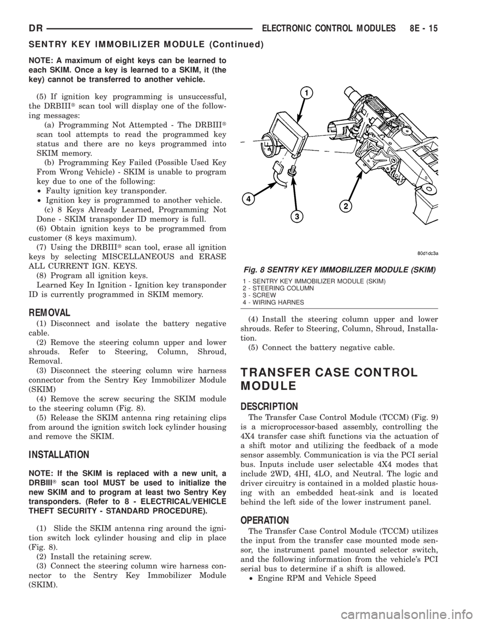
(4) Remove the screw securing the SKIM module
to the steering column (Fig. 8).
(5) Release the SKIM antenna ring retaining clips
from around the ignition switch lock cylinder housing
and remove the SKIM.
INSTALLATION
NOTE: If the SKIM is replaced with a new unit, a
DRBIIITscan tool MUST be used to initialize the
new SKIM and to program at least two Sentry Key
transponders. (Refer to 8 - ELECTRICAL/VEHICLE
THEFT SECURITY - STANDARD PROCEDURE).
(1) Slide the SKIM antenna ring around the igni-
tion switch lock cylinder housing and clip in place
(Fig. 8).
(2) Install the retaining screw.
(3) Connect the steering column wire harness con-
nector to the Sentry Key Immobilizer Module
(SKIM).(4) Install the steering column upper and lower
shrouds. Refer to Steering, Column, Shroud, Installa-
tion.
(5) Connect the battery negative cable.
TRANSFER CASE CONTROL
MODULE
DESCRIPTION
The Transfer Case Control Module (TCCM) (Fig. 9)
is a microprocessor-based assembly, controlling the
4X4 transfer case shift functions via the actuation of
a shift motor and utilizing the feedback of a mode
sensor assembly. Communication is via the PCI serial
bus. Inputs include user selectable 4X4 modes that
include 2WD, 4HI, 4LO, and Neutral. The logic and
driver circuitry is contained in a molded plastic hous-
ing with an embedded heat-sink and is located
behind the left side of the lower instrument panel.
OPERATION
The Transfer Case Control Module (TCCM) utilizes
the input from the transfer case mounted mode sen-
sor, the instrument panel mounted selector switch,
and the following information from the vehicle's PCI
serial bus to determine if a shift is allowed.
²Engine RPM and Vehicle Speed
Fig. 8 SENTRY KEY IMMOBILIZER MODULE (SKIM)
1 - SENTRY KEY IMMOBILIZER MODULE (SKIM)
2 - STEERING COLUMN
3 - SCREW
4 - WIRING HARNES
DRELECTRONIC CONTROL MODULES 8E - 15
SENTRY KEY IMMOBILIZER MODULE (Continued)
Page 416 of 2895
Turn on the headlamps for fifteen seconds, then
allow up to five minutes for the battery voltage to
stabilize.
(2) Disconnect and isolate both battery cables, neg-
ative cable first.
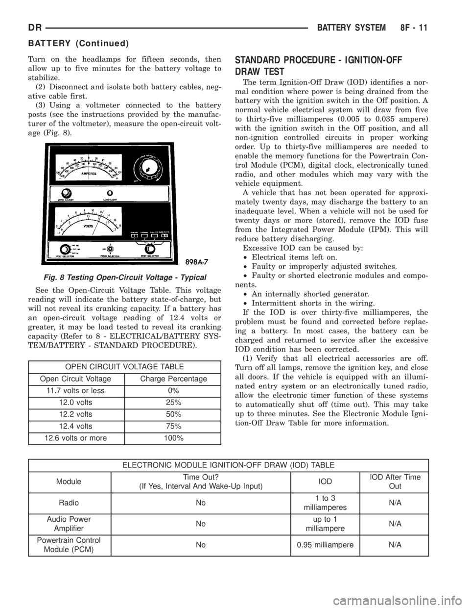
(3) Using a voltmeter connected to the battery
posts (see the instructions provided by the manufac-
turer of the voltmeter), measure the open-circuit volt-
age (Fig. 8).
See the Open-Circuit Voltage Table. This voltage
reading will indicate the battery state-of-charge, but
will not reveal its cranking capacity. If a battery has
an open-circuit voltage reading of 12.4 volts or
greater, it may be load tested to reveal its cranking
capacity (Refer to 8 - ELECTRICAL/BATTERY SYS-
TEM/BATTERY - STANDARD PROCEDURE).
OPEN CIRCUIT VOLTAGE TABLE
Open Circuit Voltage Charge Percentage
11.7 volts or less 0%
12.0 volts 25%
12.2 volts 50%
12.4 volts 75%
12.6 volts or more 100%
STANDARD PROCEDURE - IGNITION-OFF
DRAW TEST
The term Ignition-Off Draw (IOD) identifies a nor-
mal condition where power is being drained from the
battery with the ignition switch in the Off position. A
normal vehicle electrical system will draw from five
to thirty-five milliamperes (0.005 to 0.035 ampere)
with the ignition switch in the Off position, and all
non-ignition controlled circuits in proper working
order. Up to thirty-five milliamperes are needed to
enable the memory functions for the Powertrain Con-
trol Module (PCM), digital clock, electronically tuned
radio, and other modules which may vary with the
vehicle equipment.
A vehicle that has not been operated for approxi-
mately twenty days, may discharge the battery to an
inadequate level. When a vehicle will not be used for
twenty days or more (stored), remove the IOD fuse
from the Integrated Power Module (IPM). This will
reduce battery discharging.
Excessive IOD can be caused by:
²Electrical items left on.
²Faulty or improperly adjusted switches.
²Faulty or shorted electronic modules and compo-
nents.
²An internally shorted generator.
²Intermittent shorts in the wiring.
If the IOD is over thirty-five milliamperes, the
problem must be found and corrected before replac-
ing a battery. In most cases, the battery can be
charged and returned to service after the excessive
IOD condition has been corrected.
(1) Verify that all electrical accessories are off.
Turn off all lamps, remove the ignition key, and close
all doors. If the vehicle is equipped with an illumi-
nated entry system or an electronically tuned radio,
allow the electronic timer function of these systems
to automatically shut off (time out). This may take
up to three minutes. See the Electronic Module Igni-
tion-Off Draw Table for more information.
ELECTRONIC MODULE IGNITION-OFF DRAW (IOD) TABLE
ModuleTime Out?
(If Yes, Interval And Wake-Up Input)IODIOD After Time
Out
Radio No1to3
milliamperesN/A
Audio Power
AmplifierNoup to 1
milliampereN/A
Powertrain Control
Module (PCM)No 0.95 milliampere N/A
Fig. 8 Testing Open-Circuit Voltage - Typical
DRBATTERY SYSTEM 8F - 11
BATTERY (Continued)
Page 418 of 2895
WARNING: ALWAYS WEAR APPROPRIATE EYE
PROTECTION AND USE EXTREME CAUTION WHEN
WORKING WITH BATTERIES.
BATTERY TESTING
(1) If testing the battery OUT-OF-VEHICLE, clean
the battery terminals with a wire brush before test-
ing. If the battery is equipped with side post termi-
nals, install and tighten the supplied lead terminal
stud adapters. Do not use steel bolts. Failure to prop-
erly install the stud adapters, or using stud adapters
that are dirty or worn-out may result in false test
readings.
(2) If testing the battery IN-THE-VEHICLE, make
certain all of the vehicle accessory loads are OFF,
including the ignition.The preferred test position
is at the battery terminal. If the battery is not
accessible, you may test using both the positive and
negative jumper posts. Select TESTING AT JUMPER
POST when connecting to that location.
(3) Connect the tester (Fig. 9) to the battery or
jumper posts, the red clamp to positive (+) and the
black clamp to negative (±).
NOTE: Multiple batteries connected in parallel must
have the ground cable disconnected to perform a
battery test. Failure to disconnect may result in
false battery test readings.
(4) Using the ARROW key selectinoroutof vehi-
cle testing and press ENTER to make a selection.
(5) If not selected, choose the Cold Cranking Amp
(CCA) battery rating. Or select the appropriate bat-
tery rating for your area (see menu). The tester will
then run its self programmed test of the battery and
display the results. Refer to the test result table
noted below.
CAUTION: If REPLACE BATTERY is the result of the
test, this may mean a poor connection between the
vehicle's cables and battery exists. After discon-
necting the vehicle's battery cables from the bat-
tery, retest the battery using the OUT-OF-VEHICLE
test before replacing.
(6) While viewing the battery test result, press the
CODE button and the tester will prompt you for the
last 4 digits of the VIN. Use the UP/DOWN arrow
buttons to scroll to the correct character; then press
ENTER to select and move to the next digit. Then
press the ENTER button to view the SERVICE
CODE. Pressing the CODE button a second time will
return you to the test results.
BATTERY TEST RESULTS
GOOD BATTERY Return to service
GOOD - RECHARGE Fully charge battery and
return to service
CHARGE & RETEST Fully charge battery and
retest battery
REPLACE BATTERY Replace the battery and
retest complete system
BAD-CELL REPLACE Replace the battery and
retest complete system
NOTE: The SERVICE CODE is required on every
warranty claim submitted for battery replacement.
REMOVAL
(1) Turn the ignition switch to the Off position. Be
certain that all electrical accessories are turned off.
(2) Loosen the battery negative cable terminal
clamp pinch-bolt hex nut.
(3) Disconnect the battery negative cable terminal
clamp from the battery negative terminal post. If
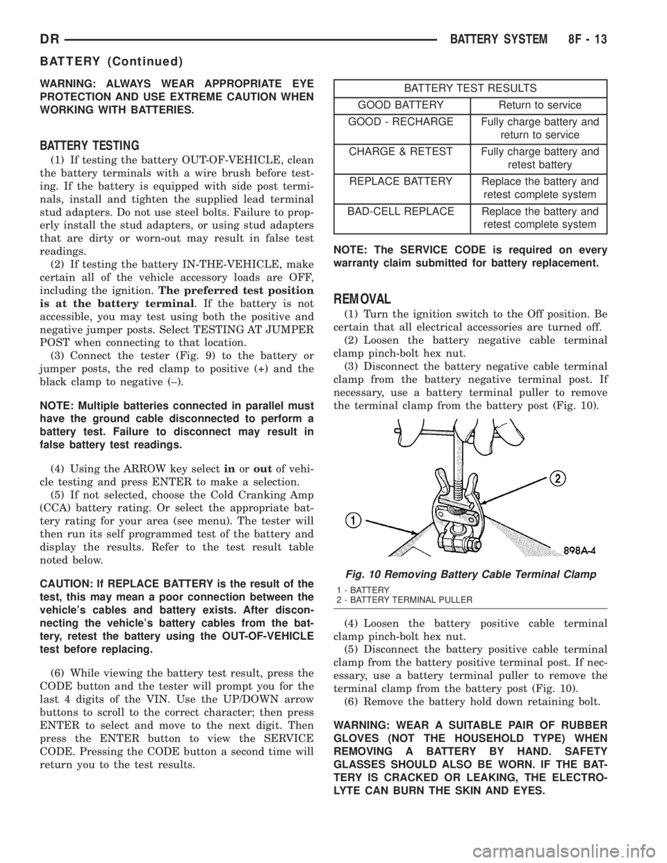
necessary, use a battery terminal puller to remove
the terminal clamp from the battery post (Fig. 10).
(4) Loosen the battery positive cable terminal
clamp pinch-bolt hex nut.
(5) Disconnect the battery positive cable terminal
clamp from the battery positive terminal post. If nec-
essary, use a battery terminal puller to remove the
terminal clamp from the battery post (Fig. 10).
(6) Remove the battery hold down retaining bolt.
WARNING: WEAR A SUITABLE PAIR OF RUBBER
GLOVES (NOT THE HOUSEHOLD TYPE) WHEN
REMOVING A BATTERY BY HAND. SAFETY
GLASSES SHOULD ALSO BE WORN. IF THE BAT-
TERY IS CRACKED OR LEAKING, THE ELECTRO-
LYTE CAN BURN THE SKIN AND EYES.
Fig. 10 Removing Battery Cable Terminal Clamp
1 - BATTERY
2 - BATTERY TERMINAL PULLER
DRBATTERY SYSTEM 8F - 13
BATTERY (Continued)
Page 433 of 2895
STARTING
TABLE OF CONTENTS
page page
STARTING
DESCRIPTION.........................28
OPERATION...........................28
DIAGNOSIS AND TESTING - STARTING
SYSTEM............................29
SPECIFICATIONS
STARTING SYSTEM...................33
SPECIFICATIONS - TORQUE - STARTING
SYSTEM............................34
STARTER MOTOR
DIAGNOSIS AND TESTING - STARTER
MOTOR .............................34REMOVAL.............................34
INSTALLATION.........................37
STARTER MOTOR RELAY
DESCRIPTION.........................38
OPERATION...........................38
DIAGNOSIS AND TESTING - STARTER RELAY . 38
REMOVAL.............................39
INSTALLATION.........................39
STARTING
DESCRIPTION
The starting system consists of:
²Starter relay
²Starter motor (including an integral starter sole-
noid)
Other components to be considered as part of start-
ing system are:
²Battery
²Battery cables
²Ignition switch and key lock cylinder
²Clutch pedal position switch (manual transmis-
sion)
²Park/neutral position switch (automatic trans-
mission)
²Wire harnesses and connections.
The Battery, Starting, and Charging systems oper-
ate in conjunction with one another, and must be
tested as a complete system. For correct operation of
starting/charging systems, all components used in
these 3 systems must perform within specifications.
When attempting to diagnose any of these systems, it
is important that you keep their interdependency in
mind.
The diagnostic procedures used in each of these
groups include the most basic conventional diagnostic
methods, to the more sophisticated On-Board Diag-
nostics (OBD) built into the Powertrain Control Mod-
ule (PCM). Use of an induction-type milliampere
ammeter, volt/ohmmeter, battery charger, carbon pile
rheostat (load tester), and 12-volt test lamp may be
required.
Certain starting system components are monitored
by the PCM and may produce a Diagnostic TroubleCode (DTC). Refer to Diagnostic Trouble Codes in
Emission Control for a list of codes.OPERATION
The starting system components form two separate
circuits. A high-amperage feed circuit that feeds the
starter motor between 150 and 350 amperes (700
amperes - diesel engine), and a low-amperage control
circuit that operates on less than 20 amperes. The
high-amperage feed circuit components include the
battery, the battery cables, the contact disc portion of
the starter solenoid, and the starter motor. The low-
amperage control circuit components include the igni-
tion switch, the clutch pedal position switch (manual
transmission), the park/neutral position switch (auto-
matic transmission), the starter relay, the electro-
magnetic windings of the starter solenoid, and the
connecting wire harness components.
If the vehicle is equipped with a manual transmis-
sion, it has a clutch pedal position switch installed in
series between the ignition switch and the coil bat-
tery terminal of the starter relay. This normally open
switch prevents the starter relay from being ener-
gized when the ignition switch is turned to the Start
position, unless the clutch pedal is depressed. This
feature prevents starter motor operation while the
clutch disc and the flywheel are engaged. The starter
relay coil ground terminal is always grounded on
vehicles with a manual transmission.
If the vehicle is equipped with an automatic trans-
mission, battery voltage is supplied through the low-
amperage control circuit to the coil battery terminal
of the starter relay when the ignition switch is
turned to the Start position. The park/neutral posi-
tion switch is installed in series between the starter
relay coil ground terminal and ground. This normally
8F - 28 STARTINGDR