weight DODGE RAM 2003 Service Repair Manual
[x] Cancel search | Manufacturer: DODGE, Model Year: 2003, Model line: RAM, Model: DODGE RAM 2003Pages: 2895, PDF Size: 83.15 MB
Page 2 of 2895
INTRODUCTION
TABLE OF CONTENTS
page page
VEHICLE SAFETY CERTIFICATION LABEL
DESCRIPTION..........................1
VEHICLE IDENTIFICATION NUMBER
DESCRIPTION..........................2
VEHICLE EMISSION CONTROL INFORMATION
(VECI)
DESCRIPTION..........................3
BODY CODE PLATE
DESCRIPTION..........................4
INTERNATIONAL VEHICLE CONTROL &
DISPLAY SYMBOLS
DESCRIPTION - INTERNATIONAL SYMBOLS . . . 6FASTENER IDENTIFICATION
DESCRIPTION..........................6
FASTENER USAGE
DESCRIPTION - FASTENER USAGE.........9
THREADED HOLE REPAIR
DESCRIPTION - THREADED HOLE REPAIR....9
METRIC SYSTEM
DESCRIPTION..........................9
TORQUE REFERENCES
DESCRIPTION.........................11
VEHICLE SAFETY
CERTIFICATION LABEL
DESCRIPTION
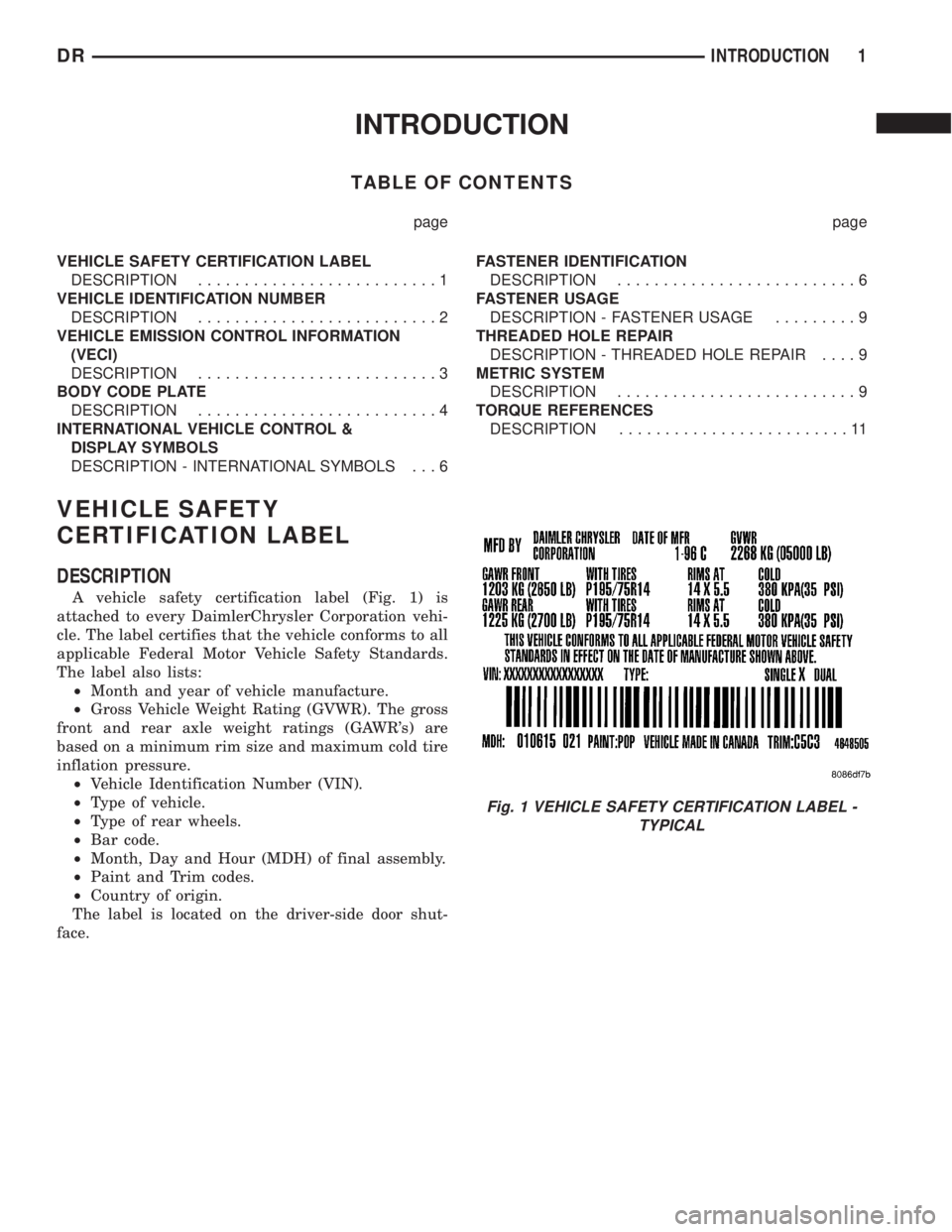
A vehicle safety certification label (Fig. 1) is
attached to every DaimlerChrysler Corporation vehi-
cle. The label certifies that the vehicle conforms to all
applicable Federal Motor Vehicle Safety Standards.
The label also lists:
²Month and year of vehicle manufacture.
²Gross Vehicle Weight Rating (GVWR). The gross
front and rear axle weight ratings (GAWR's) are
based on a minimum rim size and maximum cold tire
inflation pressure.
²Vehicle Identification Number (VIN).
²Type of vehicle.
²Type of rear wheels.
²Bar code.
²Month, Day and Hour (MDH) of final assembly.
²Paint and Trim codes.
²Country of origin.
The label is located on the driver-side door shut-
face.
Fig. 1 VEHICLE SAFETY CERTIFICATION LABEL -
TYPICAL
DRINTRODUCTION 1
Page 3 of 2895
VEHICLE IDENTIFICATION
NUMBER
DESCRIPTION
VIN CODING/LOCATIONS
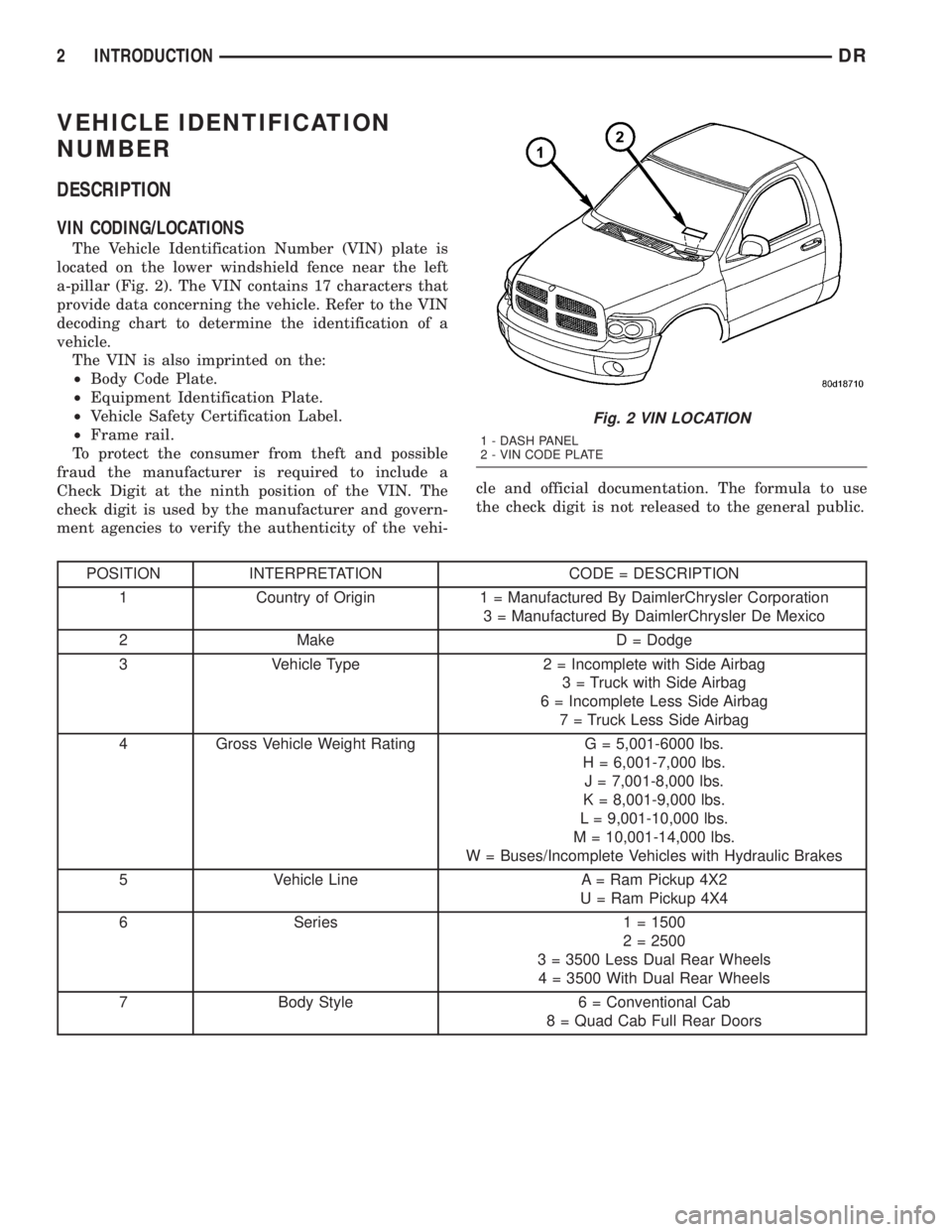
The Vehicle Identification Number (VIN) plate is
located on the lower windshield fence near the left
a-pillar (Fig. 2). The VIN contains 17 characters that
provide data concerning the vehicle. Refer to the VIN
decoding chart to determine the identification of a
vehicle.
The VIN is also imprinted on the:
²Body Code Plate.
²Equipment Identification Plate.
²Vehicle Safety Certification Label.
²Frame rail.
To protect the consumer from theft and possible
fraud the manufacturer is required to include a
Check Digit at the ninth position of the VIN. The
check digit is used by the manufacturer and govern-
ment agencies to verify the authenticity of the vehi-cle and official documentation. The formula to use
the check digit is not released to the general public.
POSITION INTERPRETATION CODE = DESCRIPTION
1 Country of Origin 1 = Manufactured By DaimlerChrysler Corporation
3 = Manufactured By DaimlerChrysler De Mexico
2 Make D = Dodge
3 Vehicle Type 2 = Incomplete with Side Airbag
3 = Truck with Side Airbag
6 = Incomplete Less Side Airbag
7 = Truck Less Side Airbag
4 Gross Vehicle Weight Rating G = 5,001-6000 lbs.
H = 6,001-7,000 lbs.
J = 7,001-8,000 lbs.
K = 8,001-9,000 lbs.
L = 9,001-10,000 lbs.
M = 10,001-14,000 lbs.
W = Buses/Incomplete Vehicles with Hydraulic Brakes
5 Vehicle Line A = Ram Pickup 4X2
U = Ram Pickup 4X4
6 Series 1 = 1500
2 = 2500
3 = 3500 Less Dual Rear Wheels
4 = 3500 With Dual Rear Wheels
7 Body Style 6 = Conventional Cab
8 = Quad Cab Full Rear Doors
Fig. 2 VIN LOCATION
1 - DASH PANEL
2 - VIN CODE PLATE
2 INTRODUCTIONDR
Page 30 of 2895
SUSPENSION
TABLE OF CONTENTS
page page
WHEEL ALIGNMENT......................1
FRONT - INDEPENDENT FRONT SUSPENSION..8FRONT - LINK/COIL......................28
REAR.................................38
WHEEL ALIGNMENT
TABLE OF CONTENTS
page page
WHEEL ALIGNMENT
DESCRIPTION..........................1
OPERATION............................2
DIAGNOSIS AND TESTING - PRE-ALIGNMENT
INSPECTION..........................2
STANDARD PROCEDURE
STANDARD PROCEDURE - HEIGHT
MEASUREMENT - 4WD (LD)..............3
STANDARD PROCEDURE - HEIGHT
ADJUSTMENT - 4WD (LD)................3
STANDARD PROCEDURE - CAMBER AND
CASTER ADJUSTMENT..................4STANDARD PROCEDURE - TOE
ADJUSTMENT.........................4
STANDARD PROCEDURE - CAMBER,
CASTER AND TOE ADJUSTMENT..........4
STANDARD PROCEDURE - ALIGNMENT
LINK/COIL SUSPENSION.................5
SPECIFICATIONS
ALIGNMENT..........................6
SPECIAL TOOLS
WHEEL ALIGNMENT....................7
WHEEL ALIGNMENT
DESCRIPTION
NOTE: Suspension components with rubber/ure-
thane bushings should be tightened with the vehi-
cle at normal ride height. It is important to have the
springs supporting the weight of the vehicle when
the fasteners are torqued. If springs are not at their
normal ride position, vehicle ride comfort could be
affected and premature bushing wear may occur.
Wheel alignment involves the correct positioning of
the wheels in relation to the vehicle. The positioning
is accomplished through suspension and steering
linkage adjustments. An alignment is considered
essential for efficient steering, good directional stabil-
ity and to minimize tire wear. The most important
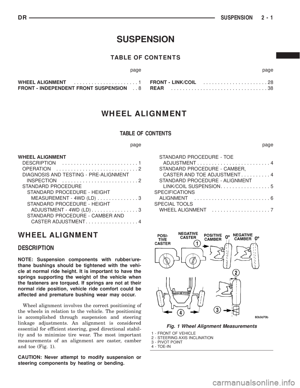
measurements of an alignment are caster, camber
and toe (Fig. 1).
CAUTION: Never attempt to modify suspension or
steering components by heating or bending.
Fig. 1 Wheel Alignment Measurements
1 - FRONT OF VEHICLE
2 - STEERING AXIS INCLINATION
3 - PIVOT POINT
4 - TOE-IN
DRSUSPENSION 2 - 1
Page 32 of 2895
CONDITION POSSIBLE CAUSES CORRECTION
EXCESSIVE STEERING
EFFORT1. Loose or worn steering gear. 1. Replace steering gear.
2. Column coupler binding. 2. Replace coupler.
3. Tire pressure. 3. Adjust tire pressure.
4. Alignment. 4. Align vehicle to specifications.
VEHICLE PULLS TO ONE
SIDE1. Tire pressure. 1. Adjust tire pressure.
2. Tire. 2. Criss-Cross Front Tires.
3. Alignment. 3. Align vehicle to specifications.
4. Loose or worn steering or
suspension components.4. Tighten or replace components as
necessary.
5. Radial tire lead. 5. Rotate or replace tire as necessary.
6. Brake pull. 6. Repair brake as necessary.
7. Weak or broken spring. 7. Replace spring.
8. Ride height (LD) 4WD only. 8. Measure and adjust ride height. (LD
only)
STANDARD PROCEDURE
STANDARD PROCEDURE - HEIGHT
MEASUREMENT - 4WD (LD)
The vehicle suspension height MUST be measured
and adjusted before performing wheel alignment pro-
cedure. Also when front suspension components have
been replaced. This measure must be performed with
the vehicle supporting it's own weight and taken on
both sides of the vehicle.
(1) Inspect tires and set to correct pressure.
(2) Jounce the front of the vehicle.
(3) Measure and record the height from the ground
at the centerline of the rear lower control arm bolt
front tip (Fig. 2).
(4) Measure and record the height from the ground
at the front spindle centerline (Static Load Radius)
(Fig. 2).
(5) Subtract the first measurement from the sec-
ond measurement. The difference between the two
measurement should be 58 mm (2.3 inches) 3mm
(0.12 inches).
(6) If value is greater than 61 mm (2.4 inches),
tighten the torsion bar bolt until the specification is
achieved (Refer to 2 - SUSPENSION/WHEEL
ALIGNMENT - STANDARD PROCEDURE).
(7) If value is less than 55 mm (2.1 inches), loosen
the torsion bar bolt until the specification is achieve-
d,(Refer to 2 - SUSPENSION/WHEEL ALIGNMENT
- STANDARD PROCEDURE).
(8) Repeat the previous steps until the ride height
is within specifications.
STANDARD PROCEDURE - HEIGHT
ADJUSTMENT - 4WD (LD)
The vehicle suspension height MUST be measured
and adjusted before performing wheel alignment pro-
cedure (Refer to 2 - SUSPENSION/WHEEL ALIGN-
MENT - STANDARD PROCEDURE). Also when
front suspension components have been replaced.
This measurement must be performed with the vehi-
cle supporting it's own weight and taken on both
sides of the vehicle.
Fig. 2 HEIGHT MESUREMENT
1 - HEIGHT FROM THE GROUND AT THE FRONT SPINDLE
CENTERLINE (STATIC LOAD RADIUS)
2 - CENTERLINE OF THE REAR LOWER CONTROL ARM BOLT
FRONT TIP
3 - GROUND LINE
DRWHEEL ALIGNMENT 2 - 3
WHEEL ALIGNMENT (Continued)
Page 33 of 2895
To adjust the vehicle height turn the torsion bar
adjustment bolt CLOCKWISE to raise the vehicle
and COUNTER CLOCKWISE to lower the vehicle.
CAUTION: ALWAYS raise the vehicle to the correct
suspension height, NEVER lower the vehicle to
obtain the correct suspension height. If the vehicle
suspension height is too high, lower the vehicle
below the height specification. Then raise the vehi-
cle to the correct suspension height specification.
This will insure the vehicle maintains the proper
suspension height.
NOTE: If a height adjustment has been made, per-
form height measurement again on both sides of
the vehicle.
STANDARD PROCEDURE - CAMBER AND
CASTER ADJUSTMENT
NOTE: 4X4 (LD) SUSPENSION HEIGHT MEASURE-
MENT MUST BE PERFORMED BEFORE AN ALIGN-
MENT.
NOTE: When the upper control arm pivot bolts are
loosened the upper control arm will normally go
inwards toward the frame automatically with the
weight of the vehicle.
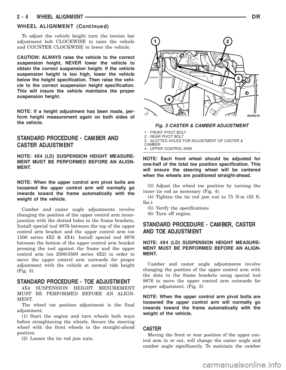
Camber and caster angle adjustments involve
changing the position of the upper control arm incon-
junction with the slotted holes in the frame brackets,
Install special tool 8876 between the top of the upper
control arm bracket and the upper control arm (on
1500 series 4X2 & 4X4). Install special tool 8876
between the bottom of the upper control arm bracket
pressing the tool against the frame and the upper
control arm (on 2500/3500 series 4X2) in order to
move the upper control arm outwards for proper
adjustment with the vehicle at normal ride height
(Fig. 3).
STANDARD PROCEDURE - TOE ADJUSTMENT
4X4 SUSPENSION HEIGHT MESUREMENT
MUST BE PERFORMED BEFORE AN ALIGN-
MENT.
The wheel toe position adjustment is the final
adjustment.
(1) Start the engine and turn wheels both ways
before straightening the wheels. Secure the steering
wheel with the front wheels in the straight-ahead
position.
(2) Loosen the tie rod jam nuts.NOTE: Each front wheel should be adjusted for
one-half of the total toe position specification. This
will ensure the steering wheel will be centered
when the wheels are positioned straight-ahead.
(3) Adjust the wheel toe position by turning the
inner tie rod as necessary (Fig. 4).
(4) Tighten the tie rod jam nut to 75 N´m (55 ft.
lbs.).
(5) Verify the specifications
(6) Turn off engine.
STANDARD PROCEDURE - CAMBER, CASTER
AND TOE ADJUSTMENT
NOTE: 4X4 (LD) SUSPENSION HEIGHT MEASURE-
MENT MUST BE PERFORMED BEFORE AN ALIGN-
MENT.
Camber and caster angle adjustments involve
changing the position of the upper control arm with
the slots in the frame brackets using special tool
8876 to move the upper control arm outwards for
proper adjustment. (Fig. 3)
NOTE: When the upper control arm pivot bolts are
loosened the upper control arm will normally go
inwards toward the frame automatically with the
weight of the vehicle.
CASTER
Moving the front or rear position of the upper con-
trol arm in or out, will change the caster angle and
camber angle significantly. To maintain the camber
Fig. 3 CASTER & CAMBER ADJUSTMENT
1 - FRONT PIVOT BOLT
2 - REAR PIVOT BOLT
3 - SLOTTED HOLES FOR ADJUSTMENT OF CASTER &
CAMBER
4 - UPPER CONTROL ARM
2 - 4 WHEEL ALIGNMENTDR
WHEEL ALIGNMENT (Continued)
Page 38 of 2895
FRONT - INDEPENDENT
FRONT SUSPENSION
DESCRIPTION
DESCRIPTION
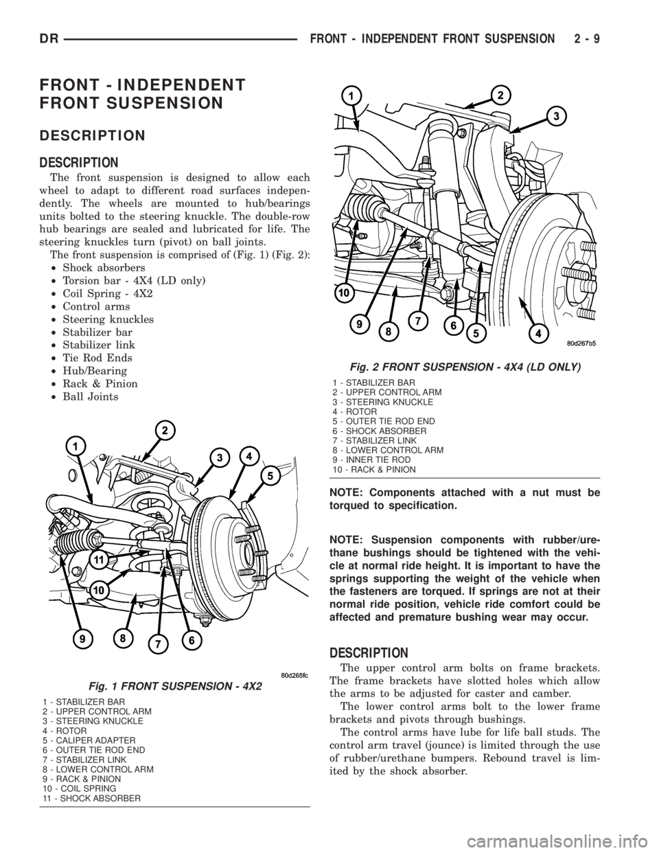
The front suspension is designed to allow each
wheel to adapt to different road surfaces indepen-
dently. The wheels are mounted to hub/bearings
units bolted to the steering knuckle. The double-row
hub bearings are sealed and lubricated for life. The
steering knuckles turn (pivot) on ball joints.
The front suspension is comprised of (Fig. 1) (Fig. 2):
²Shock absorbers
²Torsion bar - 4X4 (LD only)
²Coil Spring - 4X2
²Control arms
²Steering knuckles
²Stabilizer bar
²Stabilizer link
²Tie Rod Ends
²Hub/Bearing
²Rack & Pinion
²Ball Joints
NOTE: Components attached with a nut must be
torqued to specification.
NOTE: Suspension components with rubber/ure-
thane bushings should be tightened with the vehi-
cle at normal ride height. It is important to have the
springs supporting the weight of the vehicle when
the fasteners are torqued. If springs are not at their
normal ride position, vehicle ride comfort could be
affected and premature bushing wear may occur.
DESCRIPTION
The upper control arm bolts on frame brackets.
The frame brackets have slotted holes which allow
the arms to be adjusted for caster and camber.
The lower control arms bolt to the lower frame
brackets and pivots through bushings.
The control arms have lube for life ball studs. The
control arm travel (jounce) is limited through the use
of rubber/urethane bumpers. Rebound travel is lim-
ited by the shock absorber.
Fig. 1 FRONT SUSPENSION - 4X2
1 - STABILIZER BAR
2 - UPPER CONTROL ARM
3 - STEERING KNUCKLE
4 - ROTOR
5 - CALIPER ADAPTER
6 - OUTER TIE ROD END
7 - STABILIZER LINK
8 - LOWER CONTROL ARM
9 - RACK & PINION
10 - COIL SPRING
11 - SHOCK ABSORBER
Fig. 2 FRONT SUSPENSION - 4X4 (LD ONLY)
1 - STABILIZER BAR
2 - UPPER CONTROL ARM
3 - STEERING KNUCKLE
4 - ROTOR
5 - OUTER TIE ROD END
6 - SHOCK ABSORBER
7 - STABILIZER LINK
8 - LOWER CONTROL ARM
9 - INNER TIE ROD
10 - RACK & PINION
DRFRONT - INDEPENDENT FRONT SUSPENSION 2 - 9
Page 47 of 2895
(8) Remove the hub/bearing from the steering
knuckle (Refer to 2 - SUSPENSION/FRONT/HUB /
BEARING - REMOVAL).
INSTALLATION
CAUTION: The ball joint stud tapers must be
CLEAN and DRY before installing the knuckle.
Clean the stud tapers with mineral spirits to remove
dirt and grease.
NOTE: When installing hub/bearing with ABS
brakes, position the speed sensor opening towards
the front of the vehicle.
(1) Install the hub/bearing to the steering knuckle
and tighten the bolts to 163 N´m (120 ft. lbs.)(LD) or
176 N´m (130 ft. lbs.)(HD 4X2) (Fig. 19).
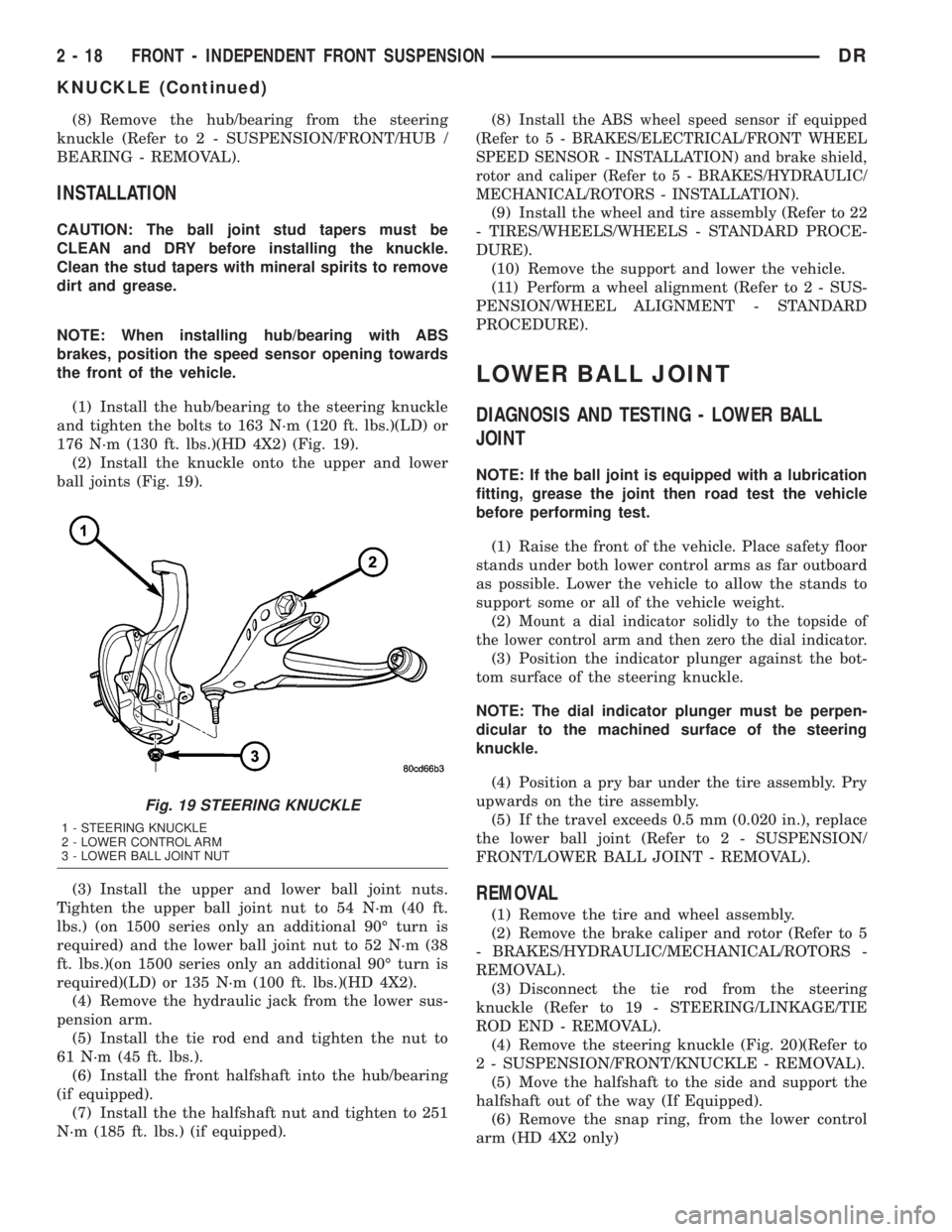
(2) Install the knuckle onto the upper and lower
ball joints (Fig. 19).
(3) Install the upper and lower ball joint nuts.
Tighten the upper ball joint nut to 54 N´m (40 ft.
lbs.) (on 1500 series only an additional 90É turn is
required) and the lower ball joint nut to 52 N´m (38
ft. lbs.)(on 1500 series only an additional 90É turn is
required)(LD) or 135 N´m (100 ft. lbs.)(HD 4X2).
(4) Remove the hydraulic jack from the lower sus-
pension arm.
(5) Install the tie rod end and tighten the nut to
61 N´m (45 ft. lbs.).
(6) Install the front halfshaft into the hub/bearing
(if equipped).
(7) Install the the halfshaft nut and tighten to 251
N´m (185 ft. lbs.) (if equipped).(8)
Install the ABS wheel speed sensor if equipped
(Refer to 5 - BRAKES/ELECTRICAL/FRONT WHEEL
SPEED SENSOR - INSTALLATION) and brake shield,
rotor and caliper (Refer to 5 - BRAKES/HYDRAULIC/
MECHANICAL/ROTORS - INSTALLATION).
(9) Install the wheel and tire assembly (Refer to 22
- TIRES/WHEELS/WHEELS - STANDARD PROCE-
DURE).
(10) Remove the support and lower the vehicle.
(11) Perform a wheel alignment (Refer to 2 - SUS-
PENSION/WHEEL ALIGNMENT - STANDARD
PROCEDURE).
LOWER BALL JOINT
DIAGNOSIS AND TESTING - LOWER BALL
JOINT
NOTE: If the ball joint is equipped with a lubrication
fitting, grease the joint then road test the vehicle
before performing test.
(1) Raise the front of the vehicle. Place safety floor
stands under both lower control arms as far outboard
as possible. Lower the vehicle to allow the stands to
support some or all of the vehicle weight.
(2)
Mount a dial indicator solidly to the topside of
the lower control arm and then zero the dial indicator.
(3) Position the indicator plunger against the bot-
tom surface of the steering knuckle.
NOTE: The dial indicator plunger must be perpen-
dicular to the machined surface of the steering
knuckle.
(4) Position a pry bar under the tire assembly. Pry
upwards on the tire assembly.
(5) If the travel exceeds 0.5 mm (0.020 in.), replace
the lower ball joint (Refer to 2 - SUSPENSION/
FRONT/LOWER BALL JOINT - REMOVAL).
REMOVAL
(1) Remove the tire and wheel assembly.
(2) Remove the brake caliper and rotor (Refer to 5
- BRAKES/HYDRAULIC/MECHANICAL/ROTORS -
REMOVAL).
(3) Disconnect the tie rod from the steering
knuckle (Refer to 19 - STEERING/LINKAGE/TIE
ROD END - REMOVAL).
(4) Remove the steering knuckle (Fig. 20)(Refer to
2 - SUSPENSION/FRONT/KNUCKLE - REMOVAL).
(5) Move the halfshaft to the side and support the
halfshaft out of the way (If Equipped).
(6) Remove the snap ring, from the lower control
arm (HD 4X2 only)
Fig. 19 STEERING KNUCKLE
1 - STEERING KNUCKLE
2 - LOWER CONTROL ARM
3 - LOWER BALL JOINT NUT
2 - 18 FRONT - INDEPENDENT FRONT SUSPENSIONDR
KNUCKLE (Continued)
Page 49 of 2895

LOWER CONTROL ARM
REMOVAL
REMOVAL - 4X4 (LD)
(1) Raise and support the vehicle.
(2) Remove the wheel and tire assembly.
(3) Remove the upper ball joint nut. Separate ball
joint from the steering knuckle with Remover 8677.
(4) Remove the front halfshaft, (Refer to 3 - DIF-
FERENTIAL & DRIVELINE/HALF SHAFT -
REMOVAL).
(5) Remove the torsion bar, (Refer to 2 - SUSPEN-
SION/FRONT/TRACK BAR - REMOVAL).
(6) Remove the shock absorber lower bolt.
(7) Remove the stabilizer bar link (Refer to 2 -
SUSPENSION/FRONT/STABILIZER LINK -
REMOVAL).
(8) Remove the lower ball joint nut. Separate ball
joint from the steering knuckle with Remover 8677.
(9) Remove the control arm pivot bolts and suspen-
sion arm from frame rail brackets (Fig. 23).
REMOVAL - 4X2
(1) Raise and support the vehicle.
(2) Remove the tire and wheel assembly.
(3) Support the lower control arm at the outboard
side of the lower control arm to support vehicle
weight.
(4) Remove the shock (Refer to 2 - SUSPENSION/
FRONT/SHOCK - REMOVAL).
(5) Install Spring Compressor DD-1278 up through
the lower suspension arm, coil spring and shock holein the frame. The bell-shaped adapter goes against
the lower suspension arm. Install the nut on top of
the tool at the shock hole.
(6) Tighten the spring compressor nut against bell-
shaped adapter finger tight then loosen 1/2 turn.
NOTE: This will hold the spring in place until the
lower suspension arm is separated from the steer-
ing knuckle.
(7) Remove the stabilizer link (Refer to 2 - SUS-
PENSION/FRONT/STABILIZER LINK - REMOVAL).
(8) Remove the lower ball joint nut at the steering
knuckle.
(9) Install Ball Joint Remover tool 8677 on the
lower ball joint and separate the ball joint from the
knuckle.
NOTE: Do not allow the upper control arm and
steering knuckle to rebound downwards they must
be supported.
(10) Support the upper control arm and steering
knuckle out of the way.
(11) Remove the lower control arm support.
(12) Tighten the spring compressor tool to allow
clearance for the lower ball joint to be removed out of
the knuckle.
(13) Loosen the tension on the spring compressor
tool slowly allowing the lower suspension arm to
pivot downward.
(14) Remove the spring compressor tool.
(15) Remove coil spring and isolator pad from the
vehicle (Fig. 26).
(16) Remove the front and rear pivot bolts (Fig.
24).
(17) Remove the lower control arm.
Fig. 23 LOWER CONTROL ARM
1 - LOWER CONTROL ARM
2 - UPPER CONTROL ARM
3 - FRONT BOLT
4 - NUTS
5 - REAR BOLT
Fig. 24 LOWER CONTROL ARM - 4X2
1 - FRONT PIVOT BOLT
2 - REAR PIVOT BOLT
3 - LOWER CONTROL ARM
2 - 20 FRONT - INDEPENDENT FRONT SUSPENSIONDR
Page 50 of 2895
INSTALLATION
INSTALLATION - 4X4 (LD)
(1) Position the lower control arm at the frame rail
brackets. Install the pivot bolts and nuts. Tighten the
nuts finger-tight.
CAUTION: The ball joint stud taper must be CLEAN
and DRY before installing the knuckle. Clean the
stud taper with mineral spirits to remove dirt and
grease.
(2) Insert the lower ball joint into the steering
knuckle. Install and tighten the retaining nut to 52
N´m (38 ft. lbs.)(on 1500 series only an additional 90É
turn is required).
(3) Install the torsion bar, (Refer to 2 - SUSPEN-
SION/FRONT/TRACK BAR - INSTALLATION).
(4) Install shock absorber lower bolt and tighten to
135 N´m (100 ft. lbs.).
(5) Install the front halfshaft, (Refer to 3 - DIF-
FERENTIAL & DRIVELINE/HALF SHAFT -
INSTALLATION).
(6) Insert the upper ball joint into the steering
knuckle. Install and tighten the retaining nut to 54
N´m (40 ft. lbs.)(on 1500 series only an additional 90É
turn is required).
(7) Install the stabilizer bar link (Refer to 2 - SUS-
PENSION/FRONT/STABILIZER LINK - INSTALLA-
TION).
(8) Tighten the lower control arm front pivot nut
to 204 N´m (150 ft. lbs.). Tighten rear pivot bolt to
204 N´m (150 ft. lbs.).
(9) Install the wheel and tire assembly,(Refer to 22
- TIRES/WHEELS/WHEELS - STANDARD PROCE-
DURE).
(10) Remove the support and lower the vehicle.
(11) Adjust the front suspension height and per-
form a wheel alignment (Refer to 2 - SUSPENSION/
WHEEL ALIGNMENT - STANDARD PROCEDURE).
INSTALLATION - 4X2
(1) Install the lower control arm into place on the
vehicle.
(2) Install the front and rear control arm pivot
bolts finger tight.
(3) Install the coil spring into the frame pocket(Re-
fer to 2 - SUSPENSION/FRONT/SPRING - INSTAL-
LATION).
(4) Install the Spring Compressor DD-1278 up
through the lower suspension arm, coil spring and
shock hole in the frame.
(5) Tighten the tool nut to compress the coil
spring.
(6) Remove the support from the upper control
arm and steering knuckle.(7) Position the lower ball joint into the steering
knuckle.
(8) Install the retaining nut on the lower ball joint
and tighten to 52 N´m (38 ft. lbs.)(on 1500 series only
an additional 90É turn is required) or 135 N´m (100
ft. lbs.)(HD 4X2 only).
(9) Support the lower control arm at the outboard
side of the lower control arm to support vehicle
weight.
(10) Remove the spring compressor tool.
(11) Install the shock absorber. (Refer to 2 - SUS-
PENSION/FRONT/SHOCK - INSTALLATION).
(12) Install the stabilizer link (Refer to 2 - SUS-
PENSION/FRONT/STABILIZER LINK - INSTALLA-
TION).
(13) Remove the lower control arm support.
(14) Install the wheel and tire assembly and lower
the vehicle. (Refer to 22 - TIRES/WHEELS/WHEELS
- STANDARD PROCEDURE).
(15) Lower the vehicle to the floor with vehicle
weight and Tighten the front and rear control arm
pivot bolts to 204 N´m (150 ft. lbs.)(LD) or 285 N´m
(210 ft. lbs.)(HD 4X2 only).
(16) Perform a wheel alignment (Refer to 2 - SUS-
PENSION/WHEEL ALIGNMENT - STANDARD
PROCEDURE).
SPRING
REMOVAL
(1) Raise and support vehicle.
(2) Remove the front wheel and tire assembly.
(3)
Support the lower control arm at the outboard
side of the lower control arm to support vehicle weight.
(4) Remove the shock absorber (Refer to 2 - SUS-
PENSION/FRONT/SHOCK - REMOVAL).
(5) Install Spring Compressor DD-1278 up through
the lower suspension arm, coil spring and shock hole
in the frame. The bell-shaped adapter goes against
the lower suspension arm. Install the nut on top of
the tool at the shock hole (Fig. 25).
(6) Tighten the spring compressor nut against bell-
shaped adapter finger tight then loosen 1/2 turn.
NOTE: This will hold the spring in place until the
lower suspension arm is separated from the steer-
ing knuckle.
(7) Remove the stabilizer link (Refer to 2 - SUS-
PENSION/FRONT/STABILIZER LINK - REMOVAL).
(8) Remove the lower ball joint nut at the steering
knuckle.
(9) Install Ball Joint Remover tool 8677 on the
lower ball joint and separate the ball joint from the
knuckle.
(10)
DRFRONT - INDEPENDENT FRONT SUSPENSION 2 - 21
LOWER CONTROL ARM (Continued)
Page 51 of 2895

NOTE: Do not allow the upper control arm and
steering knuckle to rebound downwards they must
be supported.Support the upper control arm and
steering knuckle out of the way.
(11) Remove the lower control arm support.
(12) Tighten the spring compressor tool to allow
clearance for the lower ball joint to be removed out of
the knuckle.
NOTE: It may necessary to loosen the control arm
pivot bolt to allow downward swing.
(13) Loosen the tension on the spring compressor
tool slowly allowing the lower suspension arm to
pivot downward.
(14) Remove the spring compressor tool.
(15) Remove coil spring and isolator pad from the
vehicle (Fig. 26).
INSTALLATION
(1) Tape the isolator pad to the top of the coil
spring. Position the spring in the lower suspension
arm well. Be sure that the coil spring is seated in the
well.
(2) Install Spring Compressor DD-1278 up through
the lower suspension arm, coil spring and shock hole
in the frame.
(3) Tighten the tool nut to compress the coil
spring.(4) Remove the support from the upper control
arm and steering knuckle.
(5) Position the lower ball joint into the steering
knuckle.
(6) Install the retaining nut on the lower ball joint
and tighten to 52 N´m (38 ft. lbs.)(on 1500 series only
an additional 90É turn is required) or 135 N´m (100
ft. lbs.)(HD 4X2 only).
(7) Remove the spring compressor tool.
(8) Support the lower control arm at the outboard
side of the lower control arm to support vehicle
weight.
(9) Install the shock absorber. (Refer to 2 - SUS-
PENSION/FRONT/SHOCK - INSTALLATION).
(10) Install the stabilizer link (Refer to 2 - SUS-
PENSION/FRONT/STABILIZER LINK - INSTALLA-
TION).
(11) Remove the lower control arm support.
(12) Install the wheel and tire assembly and lower
the vehicle. (Refer to 22 - TIRES/WHEELS/WHEELS
- STANDARD PROCEDURE).
(13) Lower the vehicle to the floor with vehicle
weight and Tighten the front and rear control arm
pivot bolts if loosened to 204 N´m (150 ft. lbs.)(LD) or
285 N´m (210 ft. lbs.)(HD 4X2 only).
(14) Perform a wheel alignment (Refer to 2 - SUS-
PENSION/WHEEL ALIGNMENT - STANDARD
PROCEDURE).
Fig. 25 SPRING COMPRESSOR TOOL
1 - SPECIAL TOOL DD-1278
2 - BELL-SHAPED ADAPTER
Fig. 26 COIL SPRING
1 - COIL SPRING
2 - STEERING KNUCKLE
3 - OUTER TIE ROD END
4 - LOWER CONTROL ARM
5 - SHOCK
2 - 22 FRONT - INDEPENDENT FRONT SUSPENSIONDR
SPRING (Continued)