drain bolt DODGE RAM 2003 Service Repair Manual
[x] Cancel search | Manufacturer: DODGE, Model Year: 2003, Model line: RAM, Model: DODGE RAM 2003Pages: 2895, PDF Size: 83.15 MB
Page 2383 of 2895
(2) Place replacement filter in position on valve
body and into the oil pump.
(3) Install screw to hold filter to valve body (Fig.
67). Tighten screw to 4.5 N´m (40 in. lbs.) torque.
(4) Install new cooler return filter onto the trans-
mission, if necessary. Torque the filter to 14.12 N´m
(125 in.lbs.).
(5) Place bead of MopartRTV sealant onto the
transmission case sealing surface.
(6) Place pan in position on transmission.
(7) Install bolts to hold pan to transmission.
Tighten bolts to 11.8 N´m (105 in. lbs.) torque.
(8) Lower vehicle and fill transmission with
MopartATF +4.
STANDARD PROCEDURE - TRANSMISSION
FILL
To avoid overfilling transmission after a fluid
change or overhaul, perform the following procedure:
(1) Remove dipstick and insert clean funnel in
transmission fill tube.
(2) Add following initial quantity of MopartAT F
+4 to transmission:
(a) If only fluid and filter were changed, add10
pints (5 quarts)of ATF +4 to transmission.
(b) If transmission was completely overhauled
and the torque converter was replaced or drained,
add24 pints (12 quarts)of ATF +4 to transmis-
sion.
(3) Check the transmission fluid (Refer to 21 -
TRANSMISSION/AUTOMATIC - RFE/FLUID -
STANDARD PROCEDURE) and adjust as required.
GEARSHIFT CABLE
DIAGNOSIS AND TESTING - GEARSHIFT
CABLE
(1) Engine starts must be possible with shift lever
in PARK or NEUTRAL positions only. Engine starts
must not be possible in any other gear position.
(2) With the shift lever in the:
(a) PARK position - Apply upward force on the
shift arm and remove pressure. Engine starts must
be possible.
(b) PARK position - Apply downward force on
the shift arm and remove pressure. Engine starts
must be possible.
(c) NEUTRAL position - Normal position. Engine
starts must be possible.
(d) NEUTRAL position - Engine running and
brakes applied, apply upward force on the shift
arm. Transmission shall not be able to shift from
neutral to reverse.
REMOVAL
(1) Shift transmission into PARK.
(2) Raise vehicle.
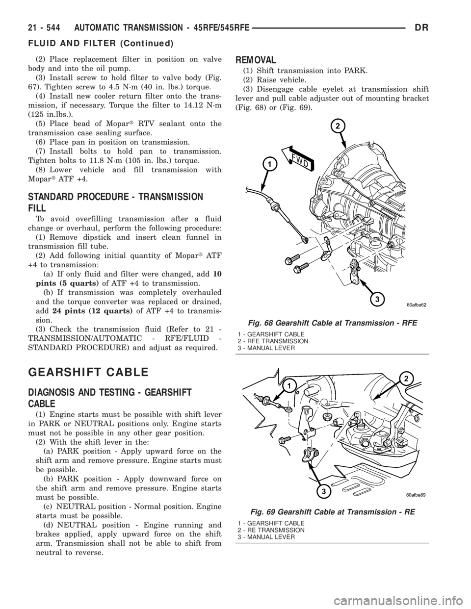
(3) Disengage cable eyelet at transmission shift
lever and pull cable adjuster out of mounting bracket
(Fig. 68) or (Fig. 69).
Fig. 68 Gearshift Cable at Transmission - RFE
1 - GEARSHIFT CABLE
2 - RFE TRANSMISSION
3 - MANUAL LEVER
Fig. 69 Gearshift Cable at Transmission - RE
1 - GEARSHIFT CABLE
2 - RE TRANSMISSION
3 - MANUAL LEVER
21 - 544 AUTOMATIC TRANSMISSION - 45RFE/545RFEDR
FLUID AND FILTER (Continued)
Page 2453 of 2895
REAR EXTENSION
(1) Install new seal in rear extension housing seal
with Installer D-163 and Handle C-4171..
(2) Apply bead of MopartGasket Maker, or equiv-
alent, to mating surface of rear extension housing.
Keep sealer bead width to maximum of 3/16 inch. Do
not use excessive amount of sealer as excess could be
displaced into output bearing.
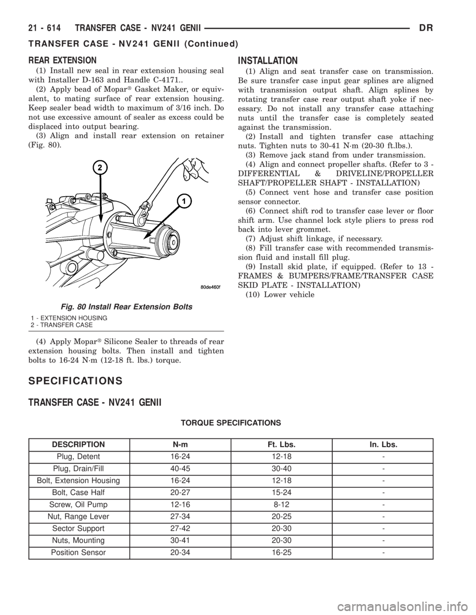
(3) Align and install rear extension on retainer
(Fig. 80).
(4) Apply MopartSilicone Sealer to threads of rear
extension housing bolts. Then install and tighten
bolts to 16-24 N´m (12-18 ft. lbs.) torque.
INSTALLATION
(1) Align and seat transfer case on transmission.
Be sure transfer case input gear splines are aligned
with transmission output shaft. Align splines by
rotating transfer case rear output shaft yoke if nec-
essary. Do not install any transfer case attaching
nuts until the transfer case is completely seated
against the transmission.
(2) Install and tighten transfer case attaching
nuts. Tighten nuts to 30-41 N´m (20-30 ft.lbs.).
(3) Remove jack stand from under transmission.
(4) Align and connect propeller shafts. (Refer to 3 -
DIFFERENTIAL & DRIVELINE/PROPELLER
SHAFT/PROPELLER SHAFT - INSTALLATION)
(5) Connect vent hose and transfer case position
sensor connector.
(6) Connect shift rod to transfer case lever or floor
shift arm. Use channel lock style pliers to press rod
back into lever grommet.
(7) Adjust shift linkage, if necessary.
(8) Fill transfer case with recommended transmis-
sion fluid and install fill plug.
(9) Install skid plate, if equipped. (Refer to 13 -
FRAMES & BUMPERS/FRAME/TRANSFER CASE
SKID PLATE - INSTALLATION)
(10) Lower vehicle
SPECIFICATIONS
TRANSFER CASE - NV241 GENII
TORQUE SPECIFICATIONS
DESCRIPTION N-m Ft. Lbs. In. Lbs.
Plug, Detent 16-24 12-18 -
Plug, Drain/Fill 40-45 30-40 -
Bolt, Extension Housing 16-24 12-18 -
Bolt, Case Half 20-27 15-24 -
Screw, Oil Pump 12-16 8-12 -
Nut, Range Lever 27-34 20-25 -
Sector Support 27-42 20-30 -
Nuts, Mounting 30-41 20-30 -
Position Sensor 20-34 16-25 -
Fig. 80 Install Rear Extension Bolts
1 - EXTENSION HOUSING
2 - TRANSFER CASE
21 - 614 TRANSFER CASE - NV241 GENIIDR
TRANSFER CASE - NV241 GENII (Continued)
Page 2464 of 2895
Condition Possible Cause Correction
Noisy in, or jumps out of, four wheel
drive low range.1) Transfer case not completely
engaged in 4L position.1) With the transmission in
NEUTRAL, or the clutch depressed
in the case of a manual
transmission and the vehicle moving
under 3-4 km/h (2-3 mph), shift the
transfer case to NEUTRAL and then
shift into the 4L position.
2) Shift linkage out of adjustment. 2) Adjust linkage.
3) Shift linkage loose or binding. 3) Tighten, lubricate, or repair
linkage as necessary.
4) Range fork damaged, inserts
worn, or fork is binding on the shift
rail.4) Disassemble unit and repair as
necessary.
5) Low range gear worn or
damaged.5) Disassemble unit and repair as
necessary.
Lubricant leaking from output shaft
seal or vent.1) Transfer case overfilled. 1) Drain lubricant to the correct
level.
2) Vent closed or restricted. 2) Clear or replace vent as
necessary.
3) Output shaft seals damaged or
installed incorrectly.3) Replace seal as necessary.
Check to ensure that another
component, the propeller shaft slip
yoke for example, is not causing
damage to seal.
Abnormal tire wear. 1) Extended operation on hard, dry
surfaces in the 4H position.1) Operate vehicle in the 2H
position on hard, dry surfaces.
REMOVAL
(1) Raise and support vehicle.
(2) Remove skid plate, if equipped. (Refer to 13 -
FRAMES & BUMPERS/FRAME/TRANSFER CASE
SKID PLATE - REMOVAL)
(3) Position drain oil container under transfer
case.
(4) Remove transfer case drain plug and drain
lubricant into container.
(5) Disconnect vent hose and transfer case position
sensor connector.
(6) Disconnect shift rod from grommet in transfer
case shift lever, or from floor shift arm whichever
provides easy access. Use channel lock style pliers to
press rod out of lever grommet.
(7) Support transmission with jack stand.
(8) Mark front and rear propeller shafts for assem-
bly reference.
(9) Remove front and rear propeller shafts. (Refer
to 3 - DIFFERENTIAL & DRIVELINE/PROPELLER
SHAFT/PROPELLER SHAFT - REMOVAL)(10) Support transfer case with suitable jack.
Secure transfer case to jack with safety chains.
(11) Remove nuts attaching transfer case to trans-
mission.
(12) Move transfer case assembly rearward until
free of transmission output shaft.
(13) Lower jack and move transfer case from
under vehicle.
DISASSEMBLY
Position transfer case in a shallow drain pan.
Remove drain plug and drain any remaining lubri-
cant remaining in case.
COMPANION FLANGE AND EXTENSION HOUSING
(1) Install two bolts 180É apart into the front out-
put shaft companion flange.
(2) Place holder over the bolts and against the
companion flange (Fig. 3).
(3) Remove and discard the front companion flange
nut.
DRTRANSFER CASE - NV271 21 - 625
TRANSFER CASE - NV271 (Continued)
Page 2488 of 2895
(7) Install the front companion flange onto the
front output shaft.
(8) Install two bolts 180É apart into the front out-
put shaft companion flange.
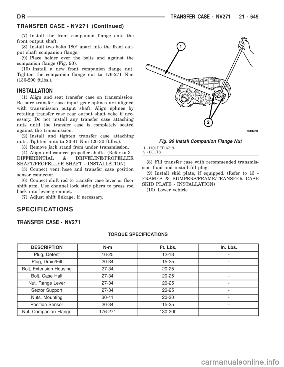
(9) Place holder over the bolts and against the
companion flange (Fig. 90).
(10) Install a new front companion flange nut.
Tighten the companion flange nut to 176-271 N´m
(130-200 ft.lbs.).
INSTALLATION
(1) Align and seat transfer case on transmission.
Be sure transfer case input gear splines are aligned
with transmission output shaft. Align splines by
rotating transfer case rear output shaft yoke if nec-
essary. Do not install any transfer case attaching
nuts until the transfer case is completely seated
against the transmission.
(2) Install and tighten transfer case attaching
nuts. Tighten nuts to 30-41 N´m (20-30 ft.lbs.).
(3) Remove jack stand from under transmission.
(4) Align and connect propeller shafts. (Refer to 3 -
DIFFERENTIAL & DRIVELINE/PROPELLER
SHAFT/PROPELLER SHAFT - INSTALLATION)
(5) Connect vent hose and transfer case position
sensor connector.
(6) Connect shift rod to transfer case lever or floor
shift arm. Use channel lock style pliers to press rod
back into lever grommet.
(7) Adjust shift linkage, if necessary.(8) Fill transfer case with recommended transmis-
sion fluid and install fill plug.
(9) Install skid plate, if equipped. (Refer to 13 -
FRAMES & BUMPERS/FRAME/TRANSFER CASE
SKID PLATE - INSTALLATION)
(10) Lower vehicle
SPECIFICATIONS
TRANSFER CASE - NV271
TORQUE SPECIFICATIONS
DESCRIPTION N-m Ft. Lbs. In. Lbs.
Plug, Detent 16-25 12-18 -
Plug, Drain/Fill 20-34 15-25 -
Bolt, Extension Housing 27-34 20-25 -
Bolt, Case Half 27-34 20-25 -
Nut, Range Lever 27-34 20-25 -
Sector Support 27-34 20-25 -
Nuts, Mounting 30-41 20-30 -
Position Sensor 20-34 15-25 -
Nut, Companion Flange 176-271 130-200 -
Fig. 90 Install Companion Flange Nut
1 - HOLDER 6719
2 - BOLTS
DRTRANSFER CASE - NV271 21 - 649
TRANSFER CASE - NV271 (Continued)
Page 2497 of 2895
TRANSFER CASE - NV243
TABLE OF CONTENTS
page page
TRANSFER CASE - NV243
DESCRIPTION........................658
OPERATION..........................659
DIAGNOSIS AND TESTING - TRANSFER
CASE - NV243.......................659
REMOVAL............................660
DISASSEMBLY........................660
CLEANING...........................668
INSPECTION.........................668
ASSEMBLY...........................670
INSTALLATION........................679
SPECIFICATIONS
TRANSFER CASE - NV243.............680
SPECIAL TOOLS
TRANSFER CASE - NV241/NV243........680
EXTENSION HOUSING BUSHING AND SEAL
REMOVAL............................682
INSTALLATION........................682FLUID
STANDARD PROCEDURE - FLUID DRAIN AND
REFILL............................682
FRONT OUTPUT SHAFT SEAL
REMOVAL............................683
INSTALLATION........................683
MODE SENSOR
DESCRIPTION........................684
OPERATION..........................684
SELECTOR SWITCH
DESCRIPTION........................685
OPERATION..........................685
SHIFT MOTOR
DESCRIPTION........................686
OPERATION..........................686
REMOVAL............................686
INSTALLATION........................686
TRANSFER CASE - NV243
DESCRIPTION
The NV243 is an electronically controlled part-time
transfer case with a low range gear reduction system.
The NV243 has three operating ranges plus a NEU-
TRAL position. The low range system provides a gear
reduction ratio for increased low speed torque capa-
bility.
The geartrain is mounted in two aluminum case
halves attached with bolts. The mainshaft front and
rear bearings are mounted in aluminum retainer
housings bolted to the case halves.
OPERATING RANGES
Transfer case operating ranges are:
²2WD (2-wheel drive)
²4HI (4-wheel drive)
²4LO (4-wheel drive low range)
²NEUTRAL
The 2WD range is for use on any road surface at
any time.The 4HI and 4LO ranges are for off road use only.
They are not for use on hard surface roads. The only
exception being when the road surface is wet or slip-
pery or covered by ice and snow.
The low range reduction gear system is operative
in 4LO range only. This range is for extra pulling
power in off road situations. Low range reduction
ratio is 2.72:1.
SHIFT MECHANISM
Operating ranges are selected with a dash
mounted shift selector switch. The shift selector
switch provides a input to the Transfer Case Control
Module (TCCM) to indicate the driver's desire to
change operating ranges. The TCCM uses this input,
along with input from the transfer case mounted
mode sensor and information from the vehicle's bus,
to determine if a shift is permitted. If the TCCM
decides the shift is permitted, the TCCM controls the
shift motor, mounted to the exterior of the transfer
case, to perform the shift.
21 - 658 TRANSFER CASE - NV243DR
Page 2519 of 2895
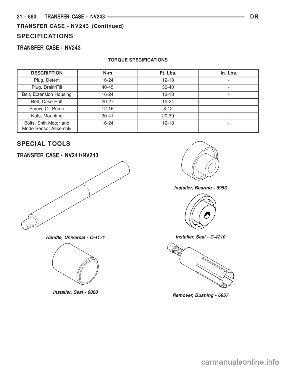
SPECIFICATIONS
TRANSFER CASE - NV243
TORQUE SPECIFICATIONS
DESCRIPTION N-m Ft. Lbs. In. Lbs.
Plug, Detent 16-24 12-18 -
Plug, Drain/Fill 40-45 30-40 -
Bolt, Extension Housing 16-24 12-18 -
Bolt, Case Half 20-27 15-24 -
Screw, Oil Pump 12-16 8-12 -
Nuts, Mounting 30-41 20-30 -
Bolts, Shift Motor and
Mode Sensor Assembly16-24 12-18 -
SPECIAL TOOLS
TRANSFER CASE - NV241/NV243
Handle, Universal - C-4171
Installer, Seal - 6888
Installer, Bearing - 6953
Installer, Seal - C-4210
Remover, Bushing - 6957
21 - 680 TRANSFER CASE - NV243DR
TRANSFER CASE - NV243 (Continued)
Page 2526 of 2895
TRANSFER CASE - NV273
TABLE OF CONTENTS
page page
TRANSFER CASE - NV273
DESCRIPTION........................687
OPERATION..........................688
DIAGNOSIS AND TESTING - TRANSFER
CASE - NV273.......................688
REMOVAL............................689
DISASSEMBLY........................689
CLEANING...........................698
INSPECTION.........................699
ASSEMBLY...........................701
INSTALLATION........................713
SPECIFICATIONS
TRANSFER CASE - NV273.............713
SPECIAL TOOLS
TRANSFER CASE NV271/NV273.........714
EXTENSION HOUSING SEAL AND DUST BOOT
REMOVAL............................716
INSTALLATION........................716FLUID
STANDARD PROCEDURE - FLUID DRAIN AND
REFILL............................716
FRONT OUTPUT SHAFT SEAL
REMOVAL............................717
INSTALLATION........................717
MODE SENSOR
DESCRIPTION........................718
OPERATION..........................718
SELECTOR SWITCH
DESCRIPTION........................719
OPERATION..........................719
SHIFT MOTOR
DESCRIPTION........................720
OPERATION..........................720
REMOVAL............................720
INSTALLATION........................720
TRANSFER CASE - NV273
DESCRIPTION
The NV273 is an electronically controlled part-time
transfer case with a low range gear reduction system.
The NV273 has three operating ranges plus a NEU-
TRAL position. The low range system provides a gear
reduction ratio for increased low speed torque capa-
bility.
The geartrain is mounted in two aluminum case
halves attached with bolts. The mainshaft front and
rear bearings are mounted in aluminum case halves.
OPERATING RANGES
Transfer case operating ranges are:
²2WD (2-wheel drive)
²4HI (4-wheel drive)
²4LO (4-wheel drive low range)
²NEUTRAL
The 2WD range is for use on any road surface at
any time.The 4HI and 4LO ranges are for off road use only.
They are not for use on hard surface roads. The only
exception being when the road surface is wet or slip-
pery or covered by ice and snow.
The low range reduction gear system is operative
in 4LO range only. This range is for extra pulling
power in off road situations. Low range reduction
ratio is 2.72:1.
SHIFT MECHANISM
Operating ranges are selected with a dash
mounted shift selector switch. The shift selector
switch provides a input to the Transfer Case Control
Module (TCCM) to indicate the driver's desire to
change operating ranges. The TCCM uses this input,
along with input from the transfer case mounted
mode sensor and information from the vehicle's bus,
to determine if a shift is permitted. If the TCCM
decides the shift is permitted, the TCCM controls the
shift motor, mounted to the exterior of the transfer
case, to perform the shift.
DRTRANSFER CASE - NV273 21 - 687
Page 2552 of 2895
(7) Install the front companion flange onto the
front output shaft.
(8) Install two bolts 180É apart into the front out-
put shaft companion flange.
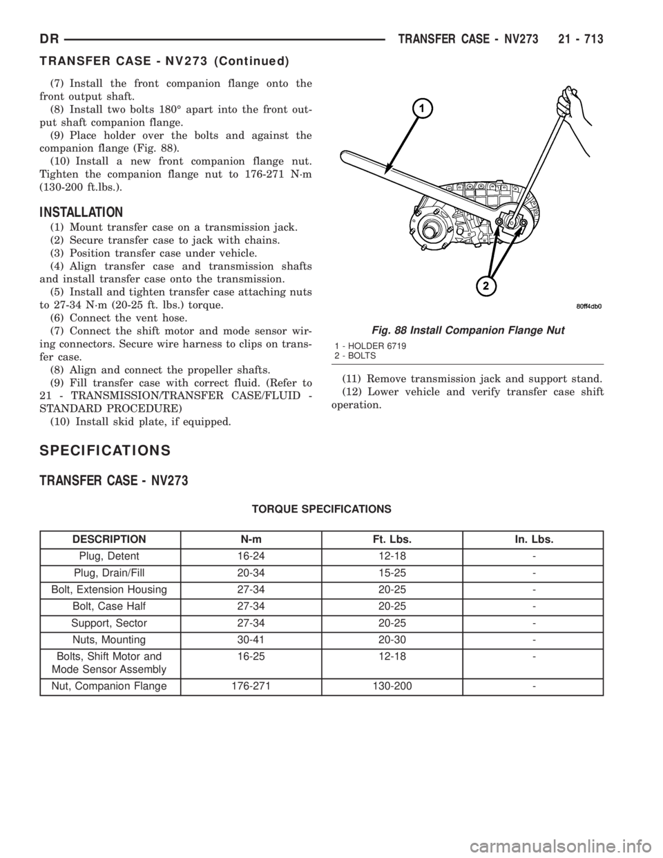
(9) Place holder over the bolts and against the
companion flange (Fig. 88).
(10) Install a new front companion flange nut.
Tighten the companion flange nut to 176-271 N´m
(130-200 ft.lbs.).
INSTALLATION
(1) Mount transfer case on a transmission jack.
(2) Secure transfer case to jack with chains.
(3) Position transfer case under vehicle.
(4) Align transfer case and transmission shafts
and install transfer case onto the transmission.
(5) Install and tighten transfer case attaching nuts
to 27-34 N´m (20-25 ft. lbs.) torque.
(6) Connect the vent hose.
(7) Connect the shift motor and mode sensor wir-
ing connectors. Secure wire harness to clips on trans-
fer case.
(8) Align and connect the propeller shafts.
(9) Fill transfer case with correct fluid. (Refer to
21 - TRANSMISSION/TRANSFER CASE/FLUID -
STANDARD PROCEDURE)
(10) Install skid plate, if equipped.(11) Remove transmission jack and support stand.
(12) Lower vehicle and verify transfer case shift
operation.
SPECIFICATIONS
TRANSFER CASE - NV273
TORQUE SPECIFICATIONS
DESCRIPTION N-m Ft. Lbs. In. Lbs.
Plug, Detent 16-24 12-18 -
Plug, Drain/Fill 20-34 15-25 -
Bolt, Extension Housing 27-34 20-25 -
Bolt, Case Half 27-34 20-25 -
Support, Sector 27-34 20-25 -
Nuts, Mounting 30-41 20-30 -
Bolts, Shift Motor and
Mode Sensor Assembly16-25 12-18 -
Nut, Companion Flange 176-271 130-200 -
Fig. 88 Install Companion Flange Nut
1 - HOLDER 6719
2 - BOLTS
DRTRANSFER CASE - NV273 21 - 713
TRANSFER CASE - NV273 (Continued)