Amplifier DODGE RAM 2003 Service Repair Manual
[x] Cancel search | Manufacturer: DODGE, Model Year: 2003, Model line: RAM, Model: DODGE RAM 2003Pages: 2895, PDF Size: 83.15 MB
Page 364 of 2895
AUDIO
TABLE OF CONTENTS
page page
AUDIO
DESCRIPTION..........................1
OPERATION............................1
DIAGNOSIS AND TESTING - AUDIO..........2
AMPLIFIER
DESCRIPTION..........................3
OPERATION............................3
REMOVAL.............................3
INSTALLATION..........................4
ANTENNA BODY & CABLE
DESCRIPTION..........................4
OPERATION............................4
DIAGNOSIS AND TESTING - ANTENNA BODY
AND CABLE..........................4
REMOVAL.............................6
INSTALLATION..........................6
INSTRUMENT PANEL ANTENNA CABLE
REMOVAL.............................6
INSTALLATION..........................7
RADIO
DESCRIPTION..........................7OPERATION............................7
REMOVAL.............................7
INSTALLATION..........................8
RADIO NOISE SUPPRESSION GROUND STRAP
DESCRIPTION..........................8
OPERATION............................8
REMOVAL.............................9
INSTALLATION.........................10
REMOTE SWITCHES
DESCRIPTION.........................10
OPERATION...........................10
DIAGNOSIS AND TESTING - REMOTE
SWITCHES..........................11
REMOVAL.............................12
INSTALLATION.........................12
SPEAKER
DESCRIPTION.........................12
OPERATION...........................12
DIAGNOSIS AND TESTING - SPEAKER......13
REMOVAL.............................13
INSTALLATION.........................15
AUDIO
DESCRIPTION
An audio system is standard factory-installed
equipment on this model. Several combinations of
radio receivers and speaker systems are offered. The
audio system uses an ignition switched source of bat-
tery current so that the system will only operate
when the ignition switch is in the RUN or ACCES-
SORY positions.
The audio system includes the following compo-
nents:
²Antenna
²Power amplifier (with premium speaker system
only)
²Radio noise suppression components
²Radio receiver
²Remote radio switches (if equipped)
²Speakers
Certain functions and features of the audio system
rely upon resources shared with other electronic
modules in the vehicle over the Programmable Com-
munication Interface (PCI) bus network. The data
bus network allows the sharing of sensor informa-
tion. For diagnosis of these electronic modules or of
the data bus network, the use of a DRB IIItscan tooland the proper Diagnostic Procedures manual are
recommended.
Refer to the appropriate wiring information for
complete standard and premium audio system circuit
diagrams. The wiring information includes proper
wire and connector repair procedures, further details
on wire harness routing and retention, as well as
pin-out and location views for the various wire har-
ness connectors, splices, and grounds.
OPERATION
The audio system components are designed to pro-
vide audio entertainment and information through
the reception, tuning and amplification of locally
broadcast radio signals in both the Amplitude Modu-
lating (AM) and Frequency Modulating (FM) com-
mercial frequency ranges.
The audio system components operate on battery
current received through a fuse in the Integrated
Power Module (IPM) on a fused ignition switch out-
put (run-acc) circuit so that the system will only
operate when the ignition switch is in the Run or
Accessory positions.
On vehicles that are equipped with the optional
remote radio switches, the Instrument Cluster
receives hard wired resistor multiplexed inputs from
the remote radio switches. The programming in the
DRAUDIO 8A - 1
Page 365 of 2895
Instrument Cluster allows it to process those inputs
and send the proper messages to the radio receiver
over the Programmable Communication Interface
(PCI) bus network to control the radio volume up or
down, station seek up or down, preset station
advance, and mode advance functions.
Refer to the owner's manual for more information
on the features, use and operation of each of the
available audio systems.
DIAGNOSIS AND TESTING - AUDIO
Any diagnosis of the Audio system should
begin with the use of the DRB IIItdiagnostic
tool. For information on the use of the DRB
IIIt, refer to the appropriate Diagnostic Service
Manual.
Refer to the appropriate wiring information. The
wiring information includes wiring diagrams, proper
wire and connector repair procedures, details of wireharness routing and retention, connector pin-out
information and location views for the various wire
harness connectors, splices and grounds.
WARNING: DISABLE THE AIRBAG SYSTEM
BEFORE ATTEMPTING ANY STEERING WHEEL,
STEERING COLUMN, SEAT BELT TENSIONER, SIDE
AIRBAG, OR INSTRUMENT PANEL COMPONENT
DIAGNOSIS OR SERVICE. DISCONNECT AND ISO-
LATE THE BATTERY NEGATIVE (GROUND) CABLE,
THEN WAIT TWO MINUTES FOR THE AIRBAG SYS-
TEM CAPACITOR TO DISCHARGE BEFORE PER-
FORMING FURTHER DIAGNOSIS OR SERVICE. THIS
IS THE ONLY SURE WAY TO DISABLE THE AIRBAG
SYSTEM. FAILURE TO TAKE THE PROPER PRE-
CAUTIONS COULD RESULT IN ACCIDENTAL AIR-
BAG DEPLOYMENT AND POSSIBLE PERSONAL
INJURY.
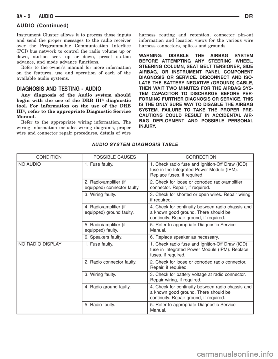
AUDIO SYSTEM DIAGNOSIS TABLE
CONDITION POSSIBLE CAUSES CORRECTION
NO AUDIO 1. Fuse faulty. 1. Check radio fuse and Ignition-Off Draw (IOD)
fuse in the Integrated Power Module (IPM).
Replace fuses, if required.
2. Radio/amplifier (if
equipped) connector faulty.2. Check for loose or corroded radio/amplifier
connector. Repair, if required.
3. Wiring faulty. 3. Check for shorted or open wires. Repair wiring,
if required.
4. Radio/amplifier (if
equipped) ground faulty.4. Check for continuity between radio chassis and
a known good ground. There should be
continuity. Repair ground, if required.
5. Radio/amplifier (if
equipped) faulty.5. Refer to appropriate Diagnostic Service
Manual.
6. Speakers faulty. 6. Replace speaker as necessary.
NO RADIO DISPLAY 1. Fuse faulty. 1. Check radio fuse and Ignition-Off Draw (IOD)
fuse in Integrated Power Module (IPM). Replace
fuses, if required.
2. Radio connector faulty. 2. Check for loose or corroded radio connector.
Repair, if required.
3. Wiring faulty. 3. Check for battery voltage at radio connector.
Repair wiring, if required.
4. Radio ground faulty. 4. Check for continuity between radio chassis and
a known good ground. There should be
continuity. Repair ground, if required.
5. Radio faulty. 5. Refer to appropriate Diagnostic Service
Manual.
8A - 2 AUDIODR
AUDIO (Continued)
Page 366 of 2895
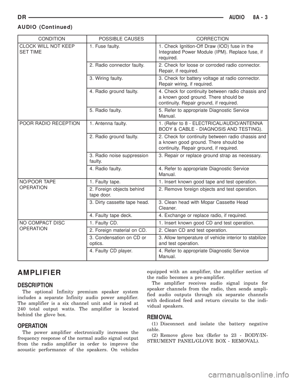
CONDITION POSSIBLE CAUSES CORRECTION
CLOCK WILL NOT KEEP
SET TIME1. Fuse faulty. 1. Check Ignition-Off Draw (IOD) fuse in the
Integrated Power Module (IPM). Replace fuse, if
required.
2. Radio connector faulty. 2. Check for loose or corroded radio connector.
Repair, if required.
3. Wiring faulty. 3. Check for battery voltage at radio connector.
Repair wiring, if required.
4. Radio ground faulty. 4. Check for continuity between radio chassis and
a known good ground. There should be
continuity. Repair ground, if required.
5. Radio faulty. 5. Refer to appropriate Diagnostic Service
Manual.
POOR RADIO RECEPTION 1. Antenna faulty. 1. (Refer to 8 - ELECTRICAL/AUDIO/ANTENNA
BODY & CABLE - DIAGNOSIS AND TESTING).
2. Radio ground faulty. 2. Check for continuity between radio chassis and
a known good ground. There should be
continuity. Repair ground, if required.
3. Radio noise suppression
faulty.3. Repair or replace ground strap as necessary.
4. Radio faulty. 4. Refer to appropriate Diagnostic Service
Manual.
NO/POOR TAPE
OPERATION1. Faulty tape. 1. Insert known good tape and test operation.
2. Foreign objects behind
tape door.2. Remove foreign objects and test operation.
3. Dirty cassette tape head. 3. Clean head with Mopar Cassette Head
Cleaner.
4. Faulty tape deck. 4. Exchange or replace radio, if required.
NO COMPACT DISC
OPERATION1. Faulty CD. 1. Insert known good CD and test operation.
2. Foreign material on CD. 2. Clean CD and test operation.
3. Condensation on CD or
optics.3. Allow temperature of vehicle interior to stabilize
and test operation.
4. Faulty CD player. 4. Refer to appropriate Diagnostic Service
Manual.
AMPLIFIER
DESCRIPTION
The optional Infinity premium speaker system
includes a separate Infinity audio power amplifier.
The amplifier is a six channel unit and is rated at
240 total output watts. The amplifier is located
behind the glove box.
OPERATION
The power amplifier electronically increases the
frequency response of the normal audio signal output
from the radio amplifier in order to improve the
acoustic performance of the speakers. On vehiclesequipped with an amplifier, the amplifier section of
the radio becomes a pre-amplifier.
The amplifier receives audio signal inputs for
speaker channels from the radio, then sends ampli-
fied audio outputs through six separate channels
with dedicated feed and return circuits to the indi-
vidual speakers.
REMOVAL
(1) Disconnect and isolate the battery negative
cable.
(2) Remove glove box (Refer to 23 - BODY/IN-
STRUMENT PANEL/GLOVE BOX - REMOVAL).
DRAUDIO 8A - 3
AUDIO (Continued)
Page 367 of 2895
(3) Remove instrument panel center bezel (Refer to
23 - BODY/INSTRUMENT PANEL/INSTRUMENT
PANEL CENTER BEZEL - REMOVAL).
(4) Remove instrument panel lower right center
bezel (Refer to 23 - BODY/INSTRUMENT PANEL/IP
LOWER RIGHT CENTER BEZEL - REMOVAL).
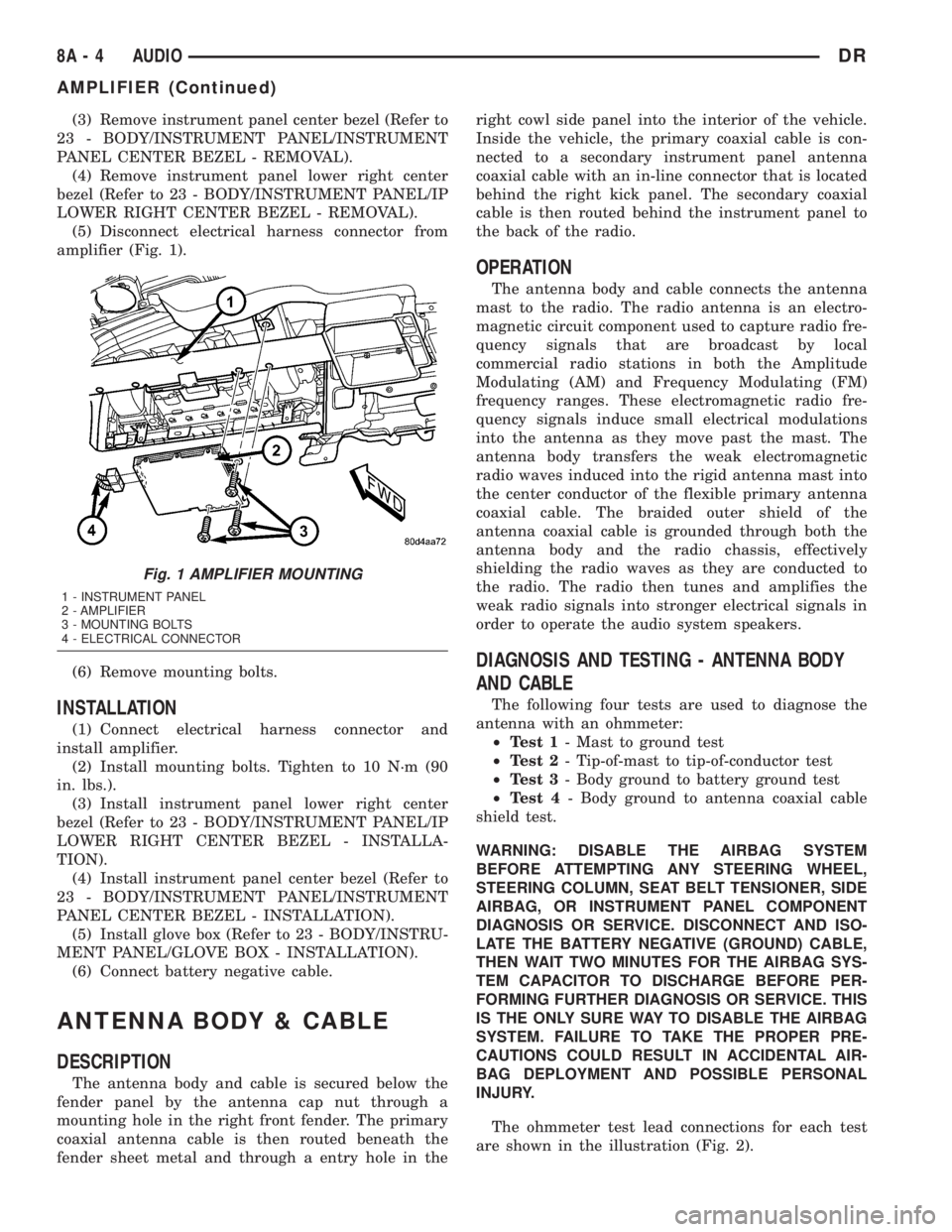
(5) Disconnect electrical harness connector from
amplifier (Fig. 1).
(6) Remove mounting bolts.
INSTALLATION
(1) Connect electrical harness connector and
install amplifier.
(2) Install mounting bolts. Tighten to 10 N´m (90
in. lbs.).
(3) Install instrument panel lower right center
bezel (Refer to 23 - BODY/INSTRUMENT PANEL/IP
LOWER RIGHT CENTER BEZEL - INSTALLA-
TION).
(4) Install instrument panel center bezel (Refer to
23 - BODY/INSTRUMENT PANEL/INSTRUMENT
PANEL CENTER BEZEL - INSTALLATION).
(5) Install glove box (Refer to 23 - BODY/INSTRU-
MENT PANEL/GLOVE BOX - INSTALLATION).
(6) Connect battery negative cable.
ANTENNA BODY & CABLE
DESCRIPTION
The antenna body and cable is secured below the
fender panel by the antenna cap nut through a
mounting hole in the right front fender. The primary
coaxial antenna cable is then routed beneath the
fender sheet metal and through a entry hole in theright cowl side panel into the interior of the vehicle.
Inside the vehicle, the primary coaxial cable is con-
nected to a secondary instrument panel antenna
coaxial cable with an in-line connector that is located
behind the right kick panel. The secondary coaxial
cable is then routed behind the instrument panel to
the back of the radio.
OPERATION
The antenna body and cable connects the antenna
mast to the radio. The radio antenna is an electro-
magnetic circuit component used to capture radio fre-
quency signals that are broadcast by local
commercial radio stations in both the Amplitude
Modulating (AM) and Frequency Modulating (FM)
frequency ranges. These electromagnetic radio fre-
quency signals induce small electrical modulations
into the antenna as they move past the mast. The
antenna body transfers the weak electromagnetic
radio waves induced into the rigid antenna mast into
the center conductor of the flexible primary antenna
coaxial cable. The braided outer shield of the
antenna coaxial cable is grounded through both the
antenna body and the radio chassis, effectively
shielding the radio waves as they are conducted to
the radio. The radio then tunes and amplifies the
weak radio signals into stronger electrical signals in
order to operate the audio system speakers.
DIAGNOSIS AND TESTING - ANTENNA BODY
AND CABLE
The following four tests are used to diagnose the
antenna with an ohmmeter:
²Test 1- Mast to ground test
²Test 2- Tip-of-mast to tip-of-conductor test
²Test 3- Body ground to battery ground test
²Test 4- Body ground to antenna coaxial cable
shield test.
WARNING: DISABLE THE AIRBAG SYSTEM
BEFORE ATTEMPTING ANY STEERING WHEEL,
STEERING COLUMN, SEAT BELT TENSIONER, SIDE
AIRBAG, OR INSTRUMENT PANEL COMPONENT
DIAGNOSIS OR SERVICE. DISCONNECT AND ISO-
LATE THE BATTERY NEGATIVE (GROUND) CABLE,
THEN WAIT TWO MINUTES FOR THE AIRBAG SYS-
TEM CAPACITOR TO DISCHARGE BEFORE PER-
FORMING FURTHER DIAGNOSIS OR SERVICE. THIS
IS THE ONLY SURE WAY TO DISABLE THE AIRBAG
SYSTEM. FAILURE TO TAKE THE PROPER PRE-
CAUTIONS COULD RESULT IN ACCIDENTAL AIR-
BAG DEPLOYMENT AND POSSIBLE PERSONAL
INJURY.
The ohmmeter test lead connections for each test
are shown in the illustration (Fig. 2).
Fig. 1 AMPLIFIER MOUNTING
1 - INSTRUMENT PANEL
2 - AMPLIFIER
3 - MOUNTING BOLTS
4 - ELECTRICAL CONNECTOR
8A - 4 AUDIODR
AMPLIFIER (Continued)
Page 371 of 2895
INSTALLATION
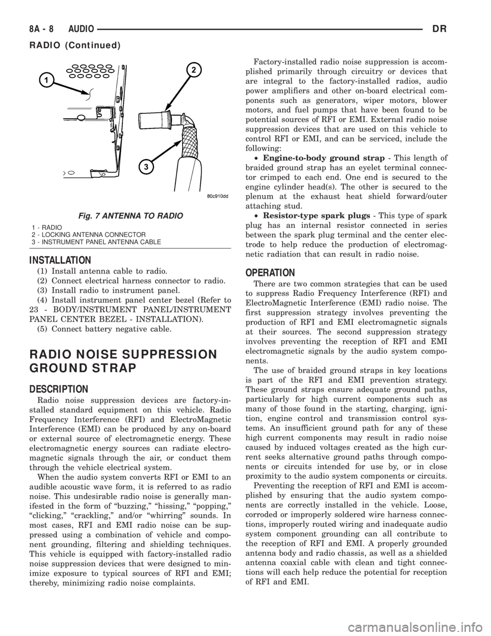
(1) Install antenna cable to radio.
(2) Connect electrical harness connector to radio.
(3) Install radio to instrument panel.
(4) Install instrument panel center bezel (Refer to
23 - BODY/INSTRUMENT PANEL/INSTRUMENT
PANEL CENTER BEZEL - INSTALLATION).
(5) Connect battery negative cable.
RADIO NOISE SUPPRESSION
GROUND STRAP
DESCRIPTION
Radio noise suppression devices are factory-in-
stalled standard equipment on this vehicle. Radio
Frequency Interference (RFI) and ElectroMagnetic
Interference (EMI) can be produced by any on-board
or external source of electromagnetic energy. These
electromagnetic energy sources can radiate electro-
magnetic signals through the air, or conduct them
through the vehicle electrical system.
When the audio system converts RFI or EMI to an
audible acoustic wave form, it is referred to as radio
noise. This undesirable radio noise is generally man-
ifested in the form of ªbuzzing,º ªhissing,º ªpopping,º
ªclicking,º ªcrackling,º and/or ªwhirringº sounds. In
most cases, RFI and EMI radio noise can be sup-
pressed using a combination of vehicle and compo-
nent grounding, filtering and shielding techniques.
This vehicle is equipped with factory-installed radio
noise suppression devices that were designed to min-
imize exposure to typical sources of RFI and EMI;
thereby, minimizing radio noise complaints.Factory-installed radio noise suppression is accom-
plished primarily through circuitry or devices that
are integral to the factory-installed radios, audio
power amplifiers and other on-board electrical com-
ponents such as generators, wiper motors, blower
motors, and fuel pumps that have been found to be
potential sources of RFI or EMI. External radio noise
suppression devices that are used on this vehicle to
control RFI or EMI, and can be serviced, include the
following:
²Engine-to-body ground strap- This length of
braided ground strap has an eyelet terminal connec-
tor crimped to each end. One end is secured to the
engine cylinder head(s). The other is secured to the
plenum at the exhaust heat shield forward/outer
attaching stud.
²Resistor-type spark plugs- This type of spark
plug has an internal resistor connected in series
between the spark plug terminal and the center elec-
trode to help reduce the production of electromag-
netic radiation that can result in radio noise.
OPERATION
There are two common strategies that can be used
to suppress Radio Frequency Interference (RFI) and
ElectroMagnetic Interference (EMI) radio noise. The
first suppression strategy involves preventing the
production of RFI and EMI electromagnetic signals
at their sources. The second suppression strategy
involves preventing the reception of RFI and EMI
electromagnetic signals by the audio system compo-
nents.
The use of braided ground straps in key locations
is part of the RFI and EMI prevention strategy.
These ground straps ensure adequate ground paths,
particularly for high current components such as
many of those found in the starting, charging, igni-
tion, engine control and transmission control sys-
tems. An insufficient ground path for any of these
high current components may result in radio noise
caused by induced voltages created as the high cur-
rent seeks alternative ground paths through compo-
nents or circuits intended for use by, or in close
proximity to the audio system components or circuits.
Preventing the reception of RFI and EMI is accom-
plished by ensuring that the audio system compo-
nents are correctly installed in the vehicle. Loose,
corroded or improperly soldered wire harness connec-
tions, improperly routed wiring and inadequate audio
system component grounding can all contribute to
the reception of RFI and EMI. A properly grounded
antenna body and radio chassis, as well as a shielded
antenna coaxial cable with clean and tight connec-
tions will each help reduce the potential for reception
of RFI and EMI.
Fig. 7 ANTENNA TO RADIO
1 - RADIO
2 - LOCKING ANTENNA CONNECTOR
3 - INSTRUMENT PANEL ANTENNA CABLE
8A - 8 AUDIODR
RADIO (Continued)
Page 375 of 2895
REMOVAL
WARNING: DISABLE THE AIRBAG SYSTEM
BEFORE ATTEMPTING ANY STEERING WHEEL,
STEERING COLUMN, SEAT BELT TENSIONER, SIDE
AIRBAG, OR INSTRUMENT PANEL COMPONENT
DIAGNOSIS OR SERVICE. DISCONNECT AND ISO-
LATE THE BATTERY NEGATIVE (GROUND) CABLE,
THEN WAIT TWO MINUTES FOR THE AIRBAG SYS-
TEM CAPACITOR TO DISCHARGE BEFORE PER-
FORMING FURTHER DIAGNOSIS OR SERVICE. THIS
IS THE ONLY SURE WAY TO DISABLE THE AIRBAG
SYSTEM. FAILURE TO TAKE THE PROPER PRE-
CAUTIONS COULD RESULT IN ACCIDENTAL AIR-
BAG DEPLOYMENT AND POSSIBLE PERSONAL
INJURY.
(1) Disconnect and isolate the battery negative
cable.
(2) Remove the driver airbag from the vehicle
(Refer to 8 - ELECTRICAL/RESTRAINTS/DRIVER
AIRBAG - REMOVAL).
(3) Remove the speed control switches (Refer to 8 -
ELECTRICAL/SPEED CONTROL/SWITCH -
REMOVAL).
(4) Unplug the wire harness connector from the
remote radio switch(es).
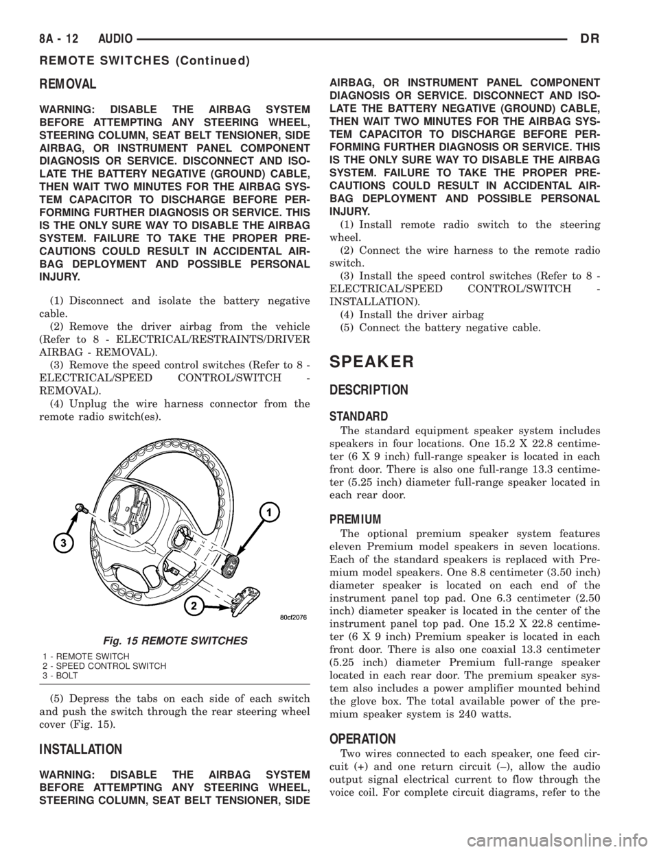
(5) Depress the tabs on each side of each switch
and push the switch through the rear steering wheel
cover (Fig. 15).
INSTALLATION
WARNING: DISABLE THE AIRBAG SYSTEM
BEFORE ATTEMPTING ANY STEERING WHEEL,
STEERING COLUMN, SEAT BELT TENSIONER, SIDEAIRBAG, OR INSTRUMENT PANEL COMPONENT
DIAGNOSIS OR SERVICE. DISCONNECT AND ISO-
LATE THE BATTERY NEGATIVE (GROUND) CABLE,
THEN WAIT TWO MINUTES FOR THE AIRBAG SYS-
TEM CAPACITOR TO DISCHARGE BEFORE PER-
FORMING FURTHER DIAGNOSIS OR SERVICE. THIS
IS THE ONLY SURE WAY TO DISABLE THE AIRBAG
SYSTEM. FAILURE TO TAKE THE PROPER PRE-
CAUTIONS COULD RESULT IN ACCIDENTAL AIR-
BAG DEPLOYMENT AND POSSIBLE PERSONAL
INJURY.
(1) Install remote radio switch to the steering
wheel.
(2) Connect the wire harness to the remote radio
switch.
(3) Install the speed control switches (Refer to 8 -
ELECTRICAL/SPEED CONTROL/SWITCH -
INSTALLATION).
(4) Install the driver airbag
(5) Connect the battery negative cable.
SPEAKER
DESCRIPTION
STANDARD
The standard equipment speaker system includes
speakers in four locations. One 15.2 X 22.8 centime-
ter (6 X 9 inch) full-range speaker is located in each
front door. There is also one full-range 13.3 centime-
ter (5.25 inch) diameter full-range speaker located in
each rear door.
PREMIUM
The optional premium speaker system features
eleven Premium model speakers in seven locations.
Each of the standard speakers is replaced with Pre-
mium model speakers. One 8.8 centimeter (3.50 inch)
diameter speaker is located on each end of the
instrument panel top pad. One 6.3 centimeter (2.50
inch) diameter speaker is located in the center of the
instrument panel top pad. One 15.2 X 22.8 centime-
ter (6 X 9 inch) Premium speaker is located in each
front door. There is also one coaxial 13.3 centimeter
(5.25 inch) diameter Premium full-range speaker
located in each rear door. The premium speaker sys-
tem also includes a power amplifier mounted behind
the glove box. The total available power of the pre-
mium speaker system is 240 watts.
OPERATION
Two wires connected to each speaker, one feed cir-
cuit (+) and one return circuit (±), allow the audio
output signal electrical current to flow through the
voice coil. For complete circuit diagrams, refer to the
Fig. 15 REMOTE SWITCHES
1 - REMOTE SWITCH
2 - SPEED CONTROL SWITCH
3 - BOLT
8A - 12 AUDIODR
REMOTE SWITCHES (Continued)
Page 376 of 2895
appropriate wiring information. The wiring informa-
tion includes wiring diagrams, proper wire and con-
nector repair procedures, details of wire harness
routing and retention, connector pin-out information
and location views for the various wire harness con-
nectors, splices and grounds.
DIAGNOSIS AND TESTING - SPEAKER
Any diagnosis of the Audio system should
begin with the use of the DRB IIItdiagnostic
tool. For information on the use of the DRB
IIIt, refer to the appropriate Diagnostic Service
Manual.
Refer to the appropriate wiring information. The
wiring information includes wiring diagrams, proper
wire and connector repair procedures, details of wire
harness routing and retention, connector pin-out
information and location views for the various wire
harness connectors, splices and grounds.
WARNING: DISABLE THE AIRBAG SYSTEM
BEFORE ATTEMPTING ANY STEERING WHEEL,
STEERING COLUMN, SEAT BELT TENSIONER, SIDE
AIRBAG, OR INSTRUMENT PANEL COMPONENT
DIAGNOSIS OR SERVICE. DISCONNECT AND ISO-
LATE THE BATTERY NEGATIVE (GROUND) CABLE,
THEN WAIT TWO MINUTES FOR THE AIRBAG SYS-
TEM CAPACITOR TO DISCHARGE BEFORE PER-
FORMING FURTHER DIAGNOSIS OR SERVICE. THIS
IS THE ONLY SURE WAY TO DISABLE THE AIRBAG
SYSTEM. FAILURE TO TAKE THE PROPER PRE-
CAUTIONS COULD RESULT IN ACCIDENTAL AIR-
BAG DEPLOYMENT AND POSSIBLE PERSONAL
INJURY.
CAUTION: The speaker output of the radio is a
ªfloating groundº system. Do not allow any speaker
lead to short to ground, as damage to the radio
and/or amplifier may result.
(1) If all speakers are inoperative, check the fuses
in the Integrated Power Module (IPM). If OK, go to
Step 2. If not OK, repair the shorted circuit or com-
ponent as required and replace the faulty fuse.
(2) Check the amplifier fuse (if equipped) in the
IPM. If OK, go to Step 3. If not OK, repair the
shorted circuit or component as required and replace
the faulty fuse.
(3) Turn the ignition switch to the ON position.
Turn the radio receiver ON. Adjust the balance and
fader control controls to check the performance of
each individual speaker. Note the speaker locations
that are not performing correctly. Go to Step 4.
(4) Turn the radio receiver OFF. Turn the ignition
OFF. Disconnect and isolate the battery negativecable. If vehicle isnotequipped with a amplifier,
remove the radio receiver. If vehicle is equipped with
an amplifier. disconnect wire harness connector at
output side of amplifier. Go to Step 5.
(5) Check both the speaker feed (+) circuit and
return (-) circuit cavities for the inoperative speaker
at the radio receiver wire harness connector for con-
tinuity to ground. There should be no continuity. If
OK, go to Step 6. If not OK, repair the shorted
speaker feed (+) and/or return (-) circuits(s) to the
speaker as required.
(6) Disconnect wire harness connector at the inop-
erative speaker. Check for continuity between the
speaker feed (+) circuit cavities of the radio receiver
wire harness connector or if equipped, the amplifier
wire harness connector and the speaker wire harness
connector. Repeat the check between the speaker
return (-) circuit cavities of the radio receiver wire
harness connector and the speaker wire harness con-
nector. In each case, there should be continuity. If
OK, replace the faulty speaker. If not OK, repair the
open speaker feed (+) and/or return (-) circuits(s) as
required.
REMOVAL
FRONT DOOR SPEAKER
(1) Disconnect and isolate the battery negative
cable.
(2) Remove front door trim panel (Refer to 23 -
BODY/DOOR - FRONT/TRIM PANEL - REMOVAL).
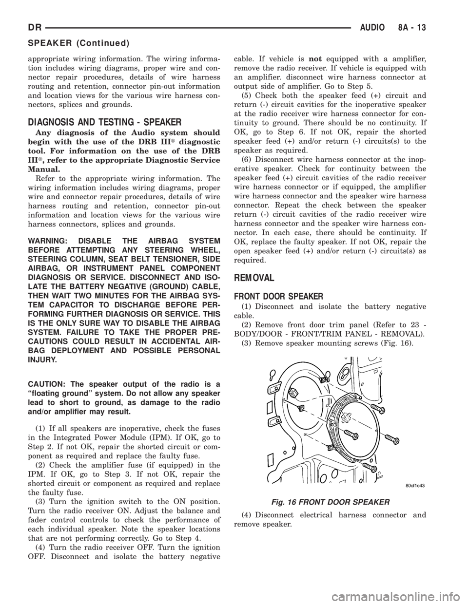
(3) Remove speaker mounting screws (Fig. 16).
(4) Disconnect electrical harness connector and
remove speaker.
Fig. 16 FRONT DOOR SPEAKER
DRAUDIO 8A - 13
SPEAKER (Continued)
Page 416 of 2895
Turn on the headlamps for fifteen seconds, then
allow up to five minutes for the battery voltage to
stabilize.
(2) Disconnect and isolate both battery cables, neg-
ative cable first.
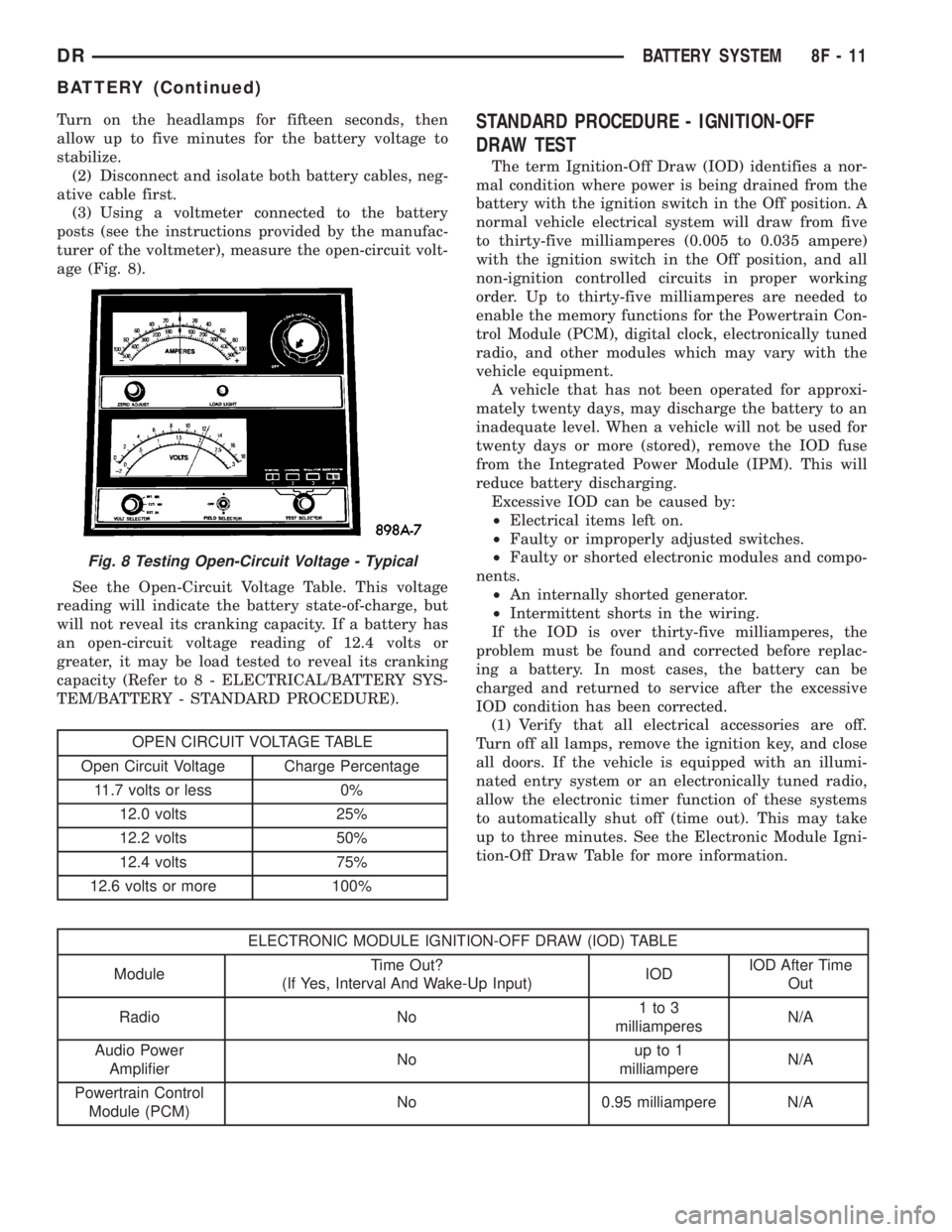
(3) Using a voltmeter connected to the battery
posts (see the instructions provided by the manufac-
turer of the voltmeter), measure the open-circuit volt-
age (Fig. 8).
See the Open-Circuit Voltage Table. This voltage
reading will indicate the battery state-of-charge, but
will not reveal its cranking capacity. If a battery has
an open-circuit voltage reading of 12.4 volts or
greater, it may be load tested to reveal its cranking
capacity (Refer to 8 - ELECTRICAL/BATTERY SYS-
TEM/BATTERY - STANDARD PROCEDURE).
OPEN CIRCUIT VOLTAGE TABLE
Open Circuit Voltage Charge Percentage
11.7 volts or less 0%
12.0 volts 25%
12.2 volts 50%
12.4 volts 75%
12.6 volts or more 100%
STANDARD PROCEDURE - IGNITION-OFF
DRAW TEST
The term Ignition-Off Draw (IOD) identifies a nor-
mal condition where power is being drained from the
battery with the ignition switch in the Off position. A
normal vehicle electrical system will draw from five
to thirty-five milliamperes (0.005 to 0.035 ampere)
with the ignition switch in the Off position, and all
non-ignition controlled circuits in proper working
order. Up to thirty-five milliamperes are needed to
enable the memory functions for the Powertrain Con-
trol Module (PCM), digital clock, electronically tuned
radio, and other modules which may vary with the
vehicle equipment.
A vehicle that has not been operated for approxi-
mately twenty days, may discharge the battery to an
inadequate level. When a vehicle will not be used for
twenty days or more (stored), remove the IOD fuse
from the Integrated Power Module (IPM). This will
reduce battery discharging.
Excessive IOD can be caused by:
²Electrical items left on.
²Faulty or improperly adjusted switches.
²Faulty or shorted electronic modules and compo-
nents.
²An internally shorted generator.
²Intermittent shorts in the wiring.
If the IOD is over thirty-five milliamperes, the
problem must be found and corrected before replac-
ing a battery. In most cases, the battery can be
charged and returned to service after the excessive
IOD condition has been corrected.
(1) Verify that all electrical accessories are off.
Turn off all lamps, remove the ignition key, and close
all doors. If the vehicle is equipped with an illumi-
nated entry system or an electronically tuned radio,
allow the electronic timer function of these systems
to automatically shut off (time out). This may take
up to three minutes. See the Electronic Module Igni-
tion-Off Draw Table for more information.
ELECTRONIC MODULE IGNITION-OFF DRAW (IOD) TABLE
ModuleTime Out?
(If Yes, Interval And Wake-Up Input)IODIOD After Time
Out
Radio No1to3
milliamperesN/A
Audio Power
AmplifierNoup to 1
milliampereN/A
Powertrain Control
Module (PCM)No 0.95 milliampere N/A
Fig. 8 Testing Open-Circuit Voltage - Typical
DRBATTERY SYSTEM 8F - 11
BATTERY (Continued)
Page 720 of 2895
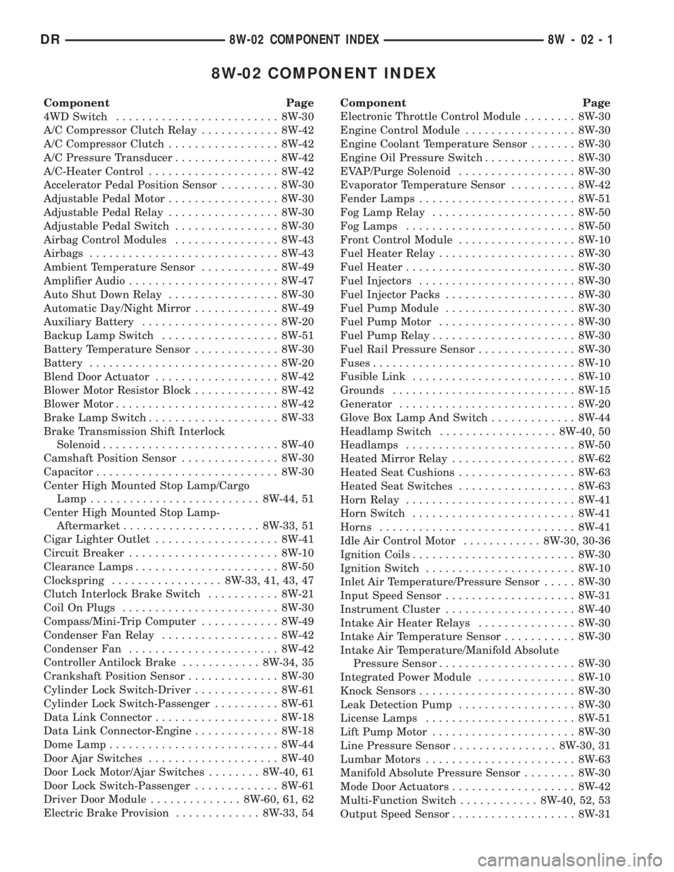
8W-02 COMPONENT INDEX
Component Page
4WD Switch......................... 8W-30
A/C Compressor Clutch Relay............ 8W-42
A/C Compressor Clutch................. 8W-42
A/C Pressure Transducer................ 8W-42
A/C-Heater Control.................... 8W-42
Accelerator Pedal Position Sensor......... 8W-30
Adjustable Pedal Motor................. 8W-30
Adjustable Pedal Relay................. 8W-30
Adjustable Pedal Switch................ 8W-30
Airbag Control Modules................ 8W-43
Airbags............................. 8W-43
Ambient Temperature Sensor............ 8W-49
Amplifier Audio....................... 8W-47
Auto Shut Down Relay................. 8W-30
Automatic Day/Night Mirror............. 8W-49
Auxiliary Battery..................... 8W-20
Backup Lamp Switch.................. 8W-51
Battery Temperature Sensor............. 8W-30
Battery............................. 8W-20
Blend Door Actuator................... 8W-42
Blower Motor Resistor Block............. 8W-42
Blower Motor......................... 8W-42
Brake Lamp Switch.................... 8W-33
Brake Transmission Shift Interlock
Solenoid........................... 8W-40
Camshaft Position Sensor............... 8W-30
Capacitor............................ 8W-30
Center High Mounted Stop Lamp/Cargo
Lamp.......................... 8W-44, 51
Center High Mounted Stop Lamp-
Aftermarket..................... 8W-33, 51
Cigar Lighter Outlet................... 8W-41
Circuit Breaker....................... 8W-10
Clearance Lamps...................... 8W-50
Clockspring................. 8W-33, 41, 43, 47
Clutch Interlock Brake Switch........... 8W-21
Coil On Plugs........................ 8W-30
Compass/Mini-Trip Computer............ 8W-49
Condenser Fan Relay.................. 8W-42
Condenser Fan....................... 8W-42
Controller Antilock Brake............ 8W-34, 35
Crankshaft Position Sensor.............. 8W-30
Cylinder Lock Switch-Driver............. 8W-61
Cylinder Lock Switch-Passenger.......... 8W-61
Data Link Connector................... 8W-18
Data Link Connector-Engine............. 8W-18
Dome Lamp.......................... 8W-44
Door Ajar Switches.................... 8W-40
Door Lock Motor/Ajar Switches........ 8W-40, 61
Door Lock Switch-Passenger............. 8W-61
Driver Door Module.............. 8W-60, 61, 62
Electric Brake Provision............. 8W-33, 54Component Page
Electronic Throttle Control Module........ 8W-30
Engine Control Module................. 8W-30
Engine Coolant Temperature Sensor....... 8W-30
Engine Oil Pressure Switch.............. 8W-30
EVAP/Purge Solenoid.................. 8W-30
Evaporator Temperature Sensor.......... 8W-42
Fender Lamps........................ 8W-51
Fog Lamp Relay...................... 8W-50
Fog Lamps.......................... 8W-50
Front Control Module.................. 8W-10
Fuel Heater Relay..................... 8W-30
Fuel Heater.......................... 8W-30
Fuel Injectors........................ 8W-30
Fuel Injector Packs.................... 8W-30
Fuel Pump Module.................... 8W-30
Fuel Pump Motor..................... 8W-30
Fuel Pump Relay...................... 8W-30
Fuel Rail Pressure Sensor............... 8W-30
Fuses............................... 8W-10
Fusible Link......................... 8W-10
Grounds............................ 8W-15
Generator........................... 8W-20
Glove Box Lamp And Switch............. 8W-44
Headlamp Switch.................. 8W-40, 50
Headlamps.......................... 8W-50
Heated Mirror Relay................... 8W-62
Heated Seat Cushions.................. 8W-63
Heated Seat Switches.................. 8W-63
Horn Relay.......................... 8W-41
Horn Switch......................... 8W-41
Horns.............................. 8W-41
Idle Air Control Motor............ 8W-30, 30-36
Ignition Coils......................... 8W-30
Ignition Switch....................... 8W-10
Inlet Air Temperature/Pressure Sensor..... 8W-30
Input Speed Sensor.................... 8W-31
Instrument Cluster.................... 8W-40
Intake Air Heater Relays............... 8W-30
Intake Air Temperature Sensor........... 8W-30
Intake Air Temperature/Manifold Absolute
Pressure Sensor..................... 8W-30
Integrated Power Module............... 8W-10
Knock Sensors........................ 8W-30
Leak Detection Pump.................. 8W-30
License Lamps....................... 8W-51
Lift Pump Motor...................... 8W-30
Line Pressure Sensor................ 8W-30, 31
Lumbar Motors....................... 8W-63
Manifold Absolute Pressure Sensor........ 8W-30
Mode Door Actuators................... 8W-42
Multi-Function Switch............ 8W-40, 52, 53
Output Speed Sensor................... 8W-31
DR8W-02 COMPONENT INDEX 8W - 02 - 1
Page 722 of 2895
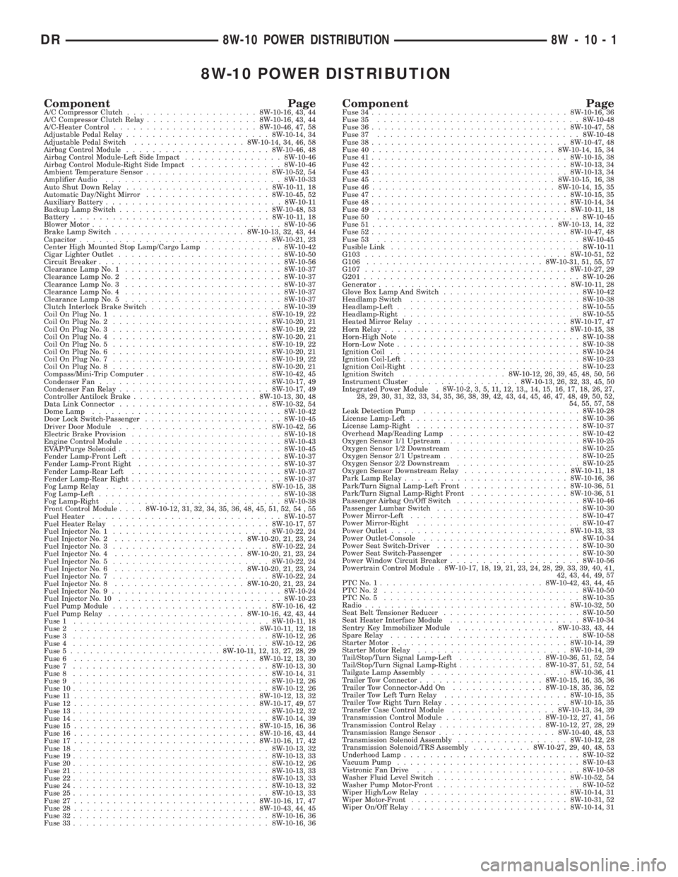
8W-10 POWER DISTRIBUTION
Component PageA/C Compressor Clutch....................8W-10-16, 43, 44
A/C Compressor Clutch Relay.................8W-10-16, 43, 44
A/C-Heater Control......................8W-10-46, 47, 58
Adjustable Pedal Relay......................8W-10-14, 34
Adjustable Pedal Switch.................8W-10-14, 34, 46, 58
Airbag Control Module......................8W-10-46, 48
Airbag Control Module-Left Side Impact...............8W-10-46
Airbag Control Module-Right Side Impact..............8W-10-46
Ambient Temperature Sensor...................8W-10-52, 54
Amplifier Audio...........................8W-10-33
Auto Shut Down Relay......................8W-10-11, 18
Automatic Day/Night Mirror...................8W-10-45, 52
Auxiliary Battery...........................8W-10-11
Backup Lamp Switch.......................8W-10-48, 53
Battery..............................8W-10-11, 18
Blower Motor.............................8W-10-56
Brake Lamp Switch....................8W-10-13, 32, 43, 44
Capacitor.............................8W-10-21, 23
Center High Mounted Stop Lamp/Cargo Lamp............8W-10-42
Cigar Lighter Outlet.........................8W-10-50
Circuit Breaker............................8W-10-56
Clearance Lamp No. 1........................8W-10-37
Clearance Lamp No. 2........................8W-10-37
Clearance Lamp No. 3........................8W-10-37
Clearance Lamp No. 4........................8W-10-37
Clearance Lamp No. 5........................8W-10-37
Clutch Interlock Brake Switch....................8W-10-39
Coil On Plug No. 1........................8W-10-19, 22
Coil On Plug No. 2........................8W-10-20, 21
Coil On Plug No. 3........................8W-10-19, 22
Coil On Plug No. 4........................8W-10-20, 21
Coil On Plug No. 5........................8W-10-19, 22
Coil On Plug No. 6........................8W-10-20, 21
Coil On Plug No. 7........................8W-10-19, 22
Coil On Plug No. 8........................8W-10-20, 21
Compass/Mini-Trip Computer...................8W-10-42, 45
Condenser Fan..........................8W-10-17, 49
Condenser Fan Relay.......................8W-10-17, 49
Controller Antilock Brake...................8W-10-13, 30, 48
Data Link Connector.......................8W-10-32, 54
Dome Lamp.............................8W-10-42
Door Lock Switch-Passenger.....................8W-10-45
Driver Door Module.......................8W-10-42, 56
Electric Brake Provision.......................8W-10-18
Engine Control Module........................8W-10-43
EVAP/Purge Solenoid.........................8W-10-45
Fender Lamp-Front Left.......................8W-10-37
Fender Lamp-Front Right......................8W-10-37
Fender Lamp-Rear Left.......................8W-10-37
Fender Lamp-Rear Right.......................8W-10-37
Fog Lamp Relay.........................8W-10-15, 38
Fog Lamp-Left............................8W-10-38
Fog Lamp-Right...........................8W-10-38
Front Control Module....8W-10-12, 31, 32, 34, 35, 36, 48, 45, 51, 52, 54 , 55
Fuel Heater.............................8W-10-57
Fuel Heater Relay........................8W-10-17, 57
Fuel Injector No. 1........................8W-10-22, 24
Fuel Injector No. 2....................8W-10-20, 21, 23, 24
Fuel Injector No. 3........................8W-10-22, 24
Fuel Injector No. 4....................8W-10-20, 21, 23, 24
Fuel Injector No. 5........................8W-10-22, 24
Fuel Injector No. 6....................8W-10-20, 21, 23, 24
Fuel Injector No. 7........................8W-10-22, 24
Fuel Injector No. 8....................8W-10-20, 21, 23, 24
Fuel Injector No. 9..........................8W-10-24
Fuel Injector No. 10.........................8W-10-23
Fuel Pump Module........................8W-10-16, 42
Fuel Pump Relay.....................8W-10-16, 42, 43, 44
Fuse 1..............................8W-10-11, 18
Fuse 2............................8W-10-11, 12, 18
Fuse 3..............................8W-10-12, 26
Fuse 4..............................8W-10-12, 26
Fuse 5.......................8W-10-11, 12, 13, 27, 28, 29
Fuse 6............................8W-10-12, 13, 30
Fuse 7..............................8W-10-13, 30
Fuse 8..............................8W-10-14, 31
Fuse 9..............................8W-10-12, 26
Fuse 10..............................8W-10-12, 26
Fuse 11............................8W-10-12, 13, 32
Fuse 12............................8W-10-17, 49, 57
Fuse 13..............................8W-10-12, 32
Fuse 14..............................8W-10-14, 39
Fuse 15............................8W-10-15, 16, 36
Fuse 16............................8W-10-16, 43, 44
Fuse 17............................8W-10-16, 17, 42
Fuse 18..............................8W-10-13, 32
Fuse 19..............................8W-10-13, 33
Fuse 20..............................8W-10-12, 26
Fuse 21..............................8W-10-13, 33
Fuse 22..............................8W-10-13, 33
Fuse 24..............................8W-10-13, 32
Fuse 25..............................8W-10-13, 33
Fuse 27............................8W-10-16, 17, 47
Fuse 28............................8W-10-43, 44, 45
Fuse 32..............................8W-10-16, 36
Fuse 33..............................8W-10-16, 36Component PageFuse 34..............................8W-10-16, 36
Fuse 35...............................8W-10-48
Fuse 36..............................8W-10-47, 58
Fuse 37...............................8W-10-48
Fuse 38..............................8W-10-47, 48
Fuse 40............................8W-10-14, 15, 34
Fuse 41..............................8W-10-15, 38
Fuse 42..............................8W-10-13, 34
Fuse 43..............................8W-10-13, 34
Fuse 45............................8W-10-15, 16, 38
Fuse 46............................8W-10-14, 15, 35
Fuse 47..............................8W-10-15, 35
Fuse 48..............................8W-10-14, 34
Fuse 49..............................8W-10-11, 18
Fuse 50...............................8W-10-45
Fuse 51............................8W-10-13, 14, 32
Fuse 52..............................8W-10-47, 48
Fuse 53...............................8W-10-45
Fusible Link.............................8W-10-11
G103...............................8W-10-51, 52
G106...........................8W-10-31, 51, 55, 57
G107...............................8W-10-27, 29
G201.................................8W-10-26
Generator.............................8W-10-11, 28
Glove Box Lamp And Switch.....................8W-10-42
Headlamp Switch..........................8W-10-38
Headlamp-Left............................8W-10-55
Headlamp-Right...........................8W-10-55
Heated Mirror Relay.......................8W-10-17, 47
Horn Relay............................8W-10-15, 38
Horn-High Note...........................8W-10-38
Horn-Low Note............................8W-10-38
Ignition Coil.............................8W-10-24
Ignition Coil-Left...........................8W-10-23
Ignition Coil-Right..........................8W-10-23
Ignition Switch................8W-10-12, 26, 39, 45, 48, 50, 56
Instrument Cluster................8W-10-13, 26, 32, 33, 45, 50
Integrated Power Module . 8W-10-2, 3, 5, 11, 12, 13,, 14, 15, 16, 17, 18, 26, 27,
28, 29, 30, 31, 32, 33, 34, 35, 36, 38, 39, 42, 43, 44, 45, 46, 47, 48, 49, 50, 52,
54, 55, 57, 58
Leak Detection Pump........................8W-10-28
License Lamp-Left..........................8W-10-36
License Lamp-Right.........................8W-10-37
Overhead Map/Reading Lamp....................8W-10-42
Oxygen Sensor 1/1 Upstream.....................8W-10-25
Oxygen Sensor 1/2 Downstream...................8W-10-25
Oxygen Sensor 2/1 Upstream.....................8W-10-25
Oxygen Sensor 2/2 Downstream...................8W-10-25
Oxygen Sensor Downstream Relay................8W-10-11, 18
Park Lamp Relay.........................8W-10-16, 36
Park/Turn Signal Lamp-Left Front................8W-10-36, 51
Park/Turn Signal Lamp-Right Front...............8W-10-36, 51
Passenger Airbag On/Off Switch...................8W-10-46
Passenger Lumbar Switch......................8W-10-30
Power Mirror-Left..........................8W-10-47
Power Mirror-Right.........................8W-10-47
Power Outlet...........................8W-10-13, 33
Power Outlet-Console........................8W-10-34
Power Seat Switch-Driver......................8W-10-30
Power Seat Switch-Passenger....................8W-10-30
Power Window Circuit Breaker....................8W-10-56
Powertrain Control Module . 8W-10-17, 18, 19, 21, 23, 24, 28, 29, 33, 39, 40, 41,
42, 43, 44, 49, 57
PTCNo.1.........................8W-10-42, 43, 44, 45
PTCNo.2 ..............................8W-10-50
PTCNo.5 ..............................8W-10-35
Radio...............................8W-10-32, 50
Seat Belt Tensioner Reducer.....................8W-10-50
Seat Heater Interface Module....................8W-10-34
Sentry Key Immobilizer Module...............8W-10-33, 43, 44
Spare Relay.............................8W-10-58
Starter Motor...........................8W-10-14, 39
Starter Motor Relay.......................8W-10-14, 39
Tail/Stop/Turn Signal Lamp-Left.............8W-10-36, 51, 52, 54
Tail/Stop/Turn Signal Lamp-Right.............8W-10-37, 51, 52, 54
Tailgate Lamp Assembly.....................8W-10-36, 41
Trailer Tow Connector...................8W-10-15, 16, 35, 36
Trailer Tow Connector-Add On..............8W-10-18, 35, 36, 52
Trailer Tow Left Turn Relay...................8W-10-15, 35
Trailer Tow Right Turn Relay...................8W-10-15, 35
Transfer Case Control Module................8W-10-13, 34, 39
Transmission Control Module...............8W-10-12, 27, 41, 56
Transmission Control Relay................8W-10-12, 27, 28, 29
Transmission Range Sensor..................8W-10-40, 48, 53
Transmission Solenoid Assembly.................8W-10-12, 28
Transmission Solenoid/TRS Assembly.........8W-10-27, 29, 40, 48, 53
Underhood Lamp...........................8W-10-32
Vacuum Pump............................8W-10-43
Vistronic Fan Drive.........................8W-10-58
Washer Fluid Level Switch....................8W-10-52, 54
Washer Pump Motor-Front......................8W-10-52
Wiper High/Low Relay......................8W-10-14, 31
Wiper Motor-Front........................8W-10-31, 52
Wiper On/Off Relay........................8W-10-14, 31
DR8W-10 POWER DISTRIBUTION 8W - 10 - 1