brake pads DODGE RAM 2003 Service Repair Manual
[x] Cancel search | Manufacturer: DODGE, Model Year: 2003, Model line: RAM, Model: DODGE RAM 2003Pages: 2895, PDF Size: 83.15 MB
Page 121 of 2895
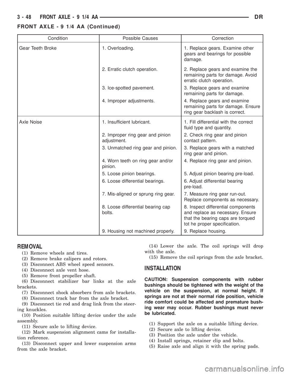
Condition Possible Causes Correction
Gear Teeth Broke 1. Overloading. 1. Replace gears. Examine other
gears and bearings for possible
damage.
2. Erratic clutch operation. 2. Replace gears and examine the
remaining parts for damage. Avoid
erratic clutch operation.
3. Ice-spotted pavement. 3. Replace gears and examine
remaining parts for damage.
4. Improper adjustments. 4. Replace gears and examine
remaining parts for damage. Ensure
ring gear backlash is correct.
Axle Noise 1. Insufficient lubricant. 1. Fill differential with the correct
fluid type and quantity.
2. Improper ring gear and pinion
adjustment.2. Check ring gear and pinion
contact pattern.
3. Unmatched ring gear and pinion. 3. Replace gears with a matched
ring gear and pinion.
4. Worn teeth on ring gear and/or
pinion.4. Replace ring gear and pinion.
5. Loose pinion bearings. 5. Adjust pinion bearing pre-load.
6. Loose differential bearings. 6. Adjust differential bearing
pre-load.
7. Mis-aligned or sprung ring gear. 7. Measure ring gear run-out.
Replace components as necessary.
8. Loose differential bearing cap
bolts.8. Inspect differential components
and replace as necessary. Ensure
that the bearing caps are torqued
tot he proper specification.
9. Housing not machined properly. 9. Replace housing.
REMOVAL
(1) Remove wheels and tires.
(2) Remove brake calipers and rotors.
(3) Disconnect ABS wheel speed sensors.
(4) Disconnect axle vent hose.
(5) Remove front propeller shaft.
(6) Disconnect stabilizer bar links at the axle
brackets.
(7) Disconnect shock absorbers from axle brackets.
(8) Disconnect track bar from the axle bracket.
(9) Disconnect tie rod and drag link from the steer-
ing knuckles.
(10) Position suitable lifting device under the axle
assembly.
(11) Secure axle to lifting device.
(12) Mark suspension alignment cams for installa-
tion reference.
(13) Disconnect upper and lower suspension arms
from the axle bracket.(14) Lower the axle. The coil springs will drop
with the axle.
(15) Remove the coil springs from the axle bracket.
INSTALLATION
CAUTION: Suspension components with rubber
bushings should be tightened with the weight of the
vehicle on the suspension, at normal height. If
springs are not at their normal ride position, vehicle
ride comfort could be affected and premature bush-
ing wear may occur. Rubber bushings must never
be lubricated.
(1) Support the axle on a suitable lifting device.
(2) Secure axle to lifting device.
(3) Position the axle under the vehicle.
(4) Install springs, retainer clip and bolts.
(5) Raise axle and align it with the spring pads.
3 - 48 FRONT AXLE - 9 1/4 AADR
FRONT AXLE - 9 1/4 AA (Continued)
Page 228 of 2895
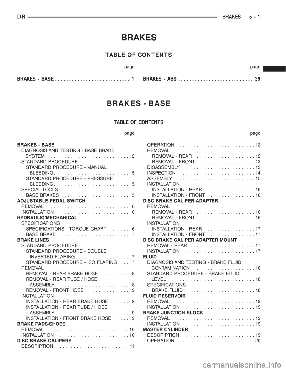
BRAKES
TABLE OF CONTENTS
page page
BRAKES - BASE........................... 1BRAKES - ABS........................... 39
BRAKES - BASE
TABLE OF CONTENTS
page page
BRAKES - BASE
DIAGNOSIS AND TESTING - BASE BRAKE
SYSTEM.............................2
STANDARD PROCEDURE
STANDARD PROCEDURE - MANUAL
BLEEDING............................5
STANDARD PROCEDURE - PRESSURE
BLEEDING............................5
SPECIAL TOOLS
BASE BRAKES........................5
ADJUSTABLE PEDAL SWITCH
REMOVAL.............................6
INSTALLATION..........................6
HYDRAULIC/MECHANICAL
SPECIFICATIONS
SPECIFICATIONS - TORQUE CHART.......6
BASE BRAKE.........................7
BRAKE LINES
STANDARD PROCEDURE
STANDARD PROCEDURE - DOUBLE
INVERTED FLARING....................7
STANDARD PROCEDURE - ISO FLARING . . . 7
REMOVAL
REMOVAL - REAR BRAKE HOSE..........8
REMOVAL - REAR TUBE / HOSE
ASSEMBLY...........................8
REMOVAL - FRONT HOSE...............9
INSTALLATION
INSTALLATION - REAR BRAKE HOSE......9
INSTALLATION - REAR TUBE / HOSE
ASSEMBLY...........................9
INSTALLATION - FRONT BRAKE HOSE.....9
BRAKE PADS/SHOES
REMOVAL.............................10
INSTALLATION.........................10
DISC BRAKE CALIPERS
DESCRIPTION.........................11OPERATION...........................12
REMOVAL
REMOVAL - REAR.....................12
REMOVAL - FRONT....................12
DISASSEMBLY.........................13
INSPECTION..........................14
ASSEMBLY............................15
INSTALLATION
INSTALLATION - REAR.................16
INSTALLATION - FRONT................16
DISC BRAKE CALIPER ADAPTER
REMOVAL
REMOVAL - REAR.....................16
REMOVAL - FRONT....................16
INSTALLATION
INSTALLATION - REAR.................17
INSTALLATION - FRONT................17
DISC BRAKE CALIPER ADAPTER MOUNT
REMOVAL - REAR......................17
INSTALLATION.........................17
FLUID
DIAGNOSIS AND TESTING - BRAKE FLUID
CONTAMINATION.....................18
STANDARD PROCEDURE - BRAKE FLUID
LEVEL..............................18
SPECIFICATIONS
BRAKE FLUID........................18
FLUID RESERVOIR
REMOVAL.............................19
INSTALLATION.........................19
BRAKE JUNCTION BLOCK
REMOVAL.............................19
INSTALLATION.........................19
MASTER CYLINDER
DESCRIPTION.........................19
OPERATION...........................20
DRBRAKES 5 - 1
Page 237 of 2895
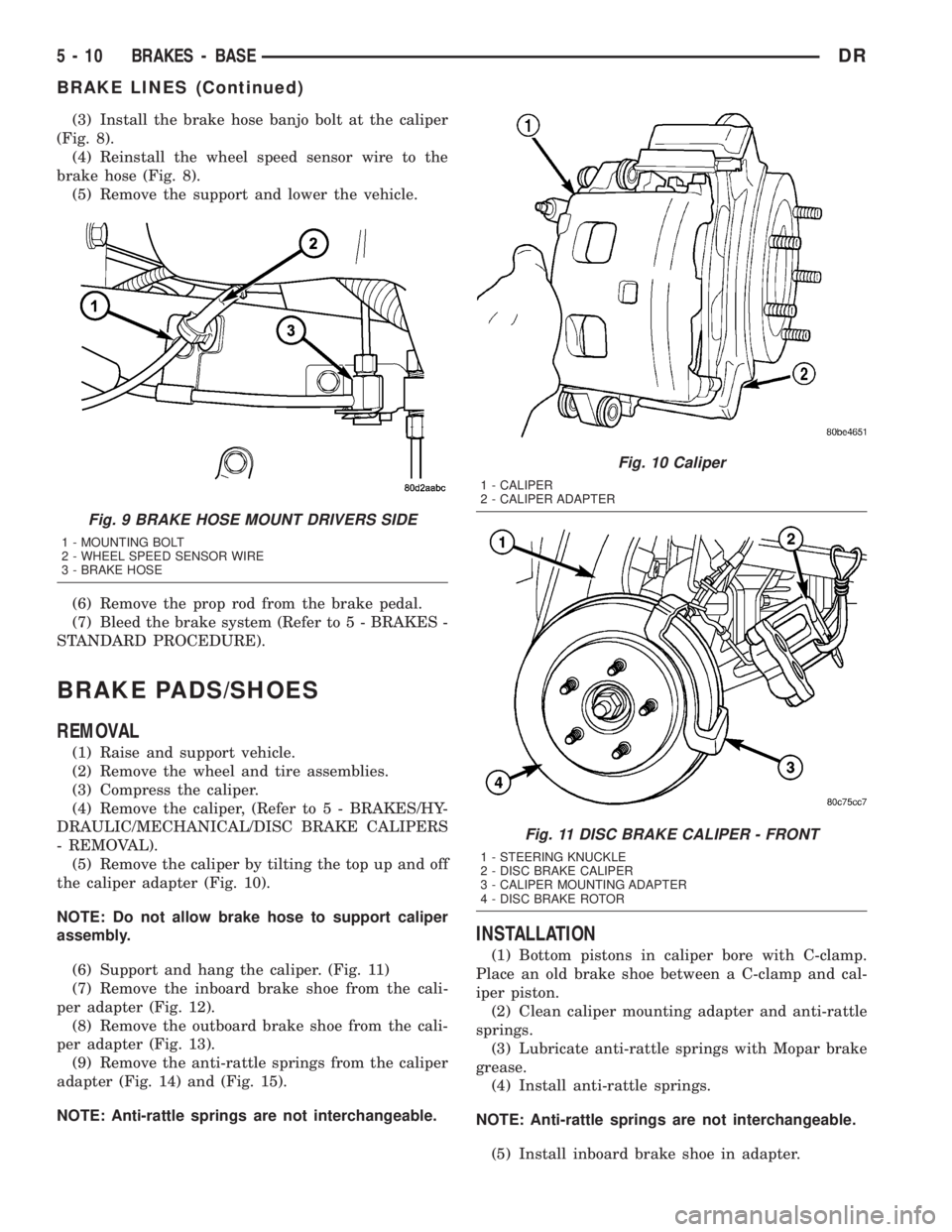
(3) Install the brake hose banjo bolt at the caliper
(Fig. 8).
(4) Reinstall the wheel speed sensor wire to the
brake hose (Fig. 8).
(5) Remove the support and lower the vehicle.
(6) Remove the prop rod from the brake pedal.
(7) Bleed the brake system (Refer to 5 - BRAKES -
STANDARD PROCEDURE).
BRAKE PADS/SHOES
REMOVAL
(1) Raise and support vehicle.
(2) Remove the wheel and tire assemblies.
(3) Compress the caliper.
(4) Remove the caliper, (Refer to 5 - BRAKES/HY-
DRAULIC/MECHANICAL/DISC BRAKE CALIPERS
- REMOVAL).
(5) Remove the caliper by tilting the top up and off
the caliper adapter (Fig. 10).
NOTE: Do not allow brake hose to support caliper
assembly.
(6) Support and hang the caliper. (Fig. 11)
(7) Remove the inboard brake shoe from the cali-
per adapter (Fig. 12).
(8) Remove the outboard brake shoe from the cali-
per adapter (Fig. 13).
(9) Remove the anti-rattle springs from the caliper
adapter (Fig. 14) and (Fig. 15).
NOTE: Anti-rattle springs are not interchangeable.
INSTALLATION
(1) Bottom pistons in caliper bore with C-clamp.
Place an old brake shoe between a C-clamp and cal-
iper piston.
(2) Clean caliper mounting adapter and anti-rattle
springs.
(3) Lubricate anti-rattle springs with Mopar brake
grease.
(4) Install anti-rattle springs.
NOTE: Anti-rattle springs are not interchangeable.
(5) Install inboard brake shoe in adapter.
Fig. 9 BRAKE HOSE MOUNT DRIVERS SIDE
1 - MOUNTING BOLT
2 - WHEEL SPEED SENSOR WIRE
3 - BRAKE HOSE
Fig. 10 Caliper
1 - CALIPER
2 - CALIPER ADAPTER
Fig. 11 DISC BRAKE CALIPER - FRONT
1 - STEERING KNUCKLE
2 - DISC BRAKE CALIPER
3 - CALIPER MOUNTING ADAPTER
4 - DISC BRAKE ROTOR
5 - 10 BRAKES - BASEDR
BRAKE LINES (Continued)
Page 238 of 2895
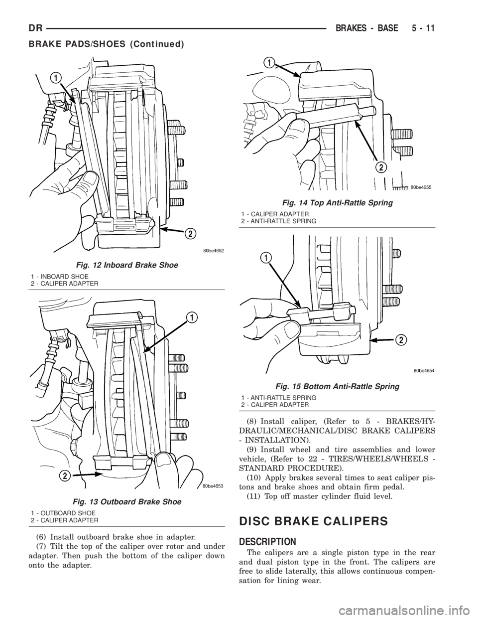
(6) Install outboard brake shoe in adapter.
(7) Tilt the top of the caliper over rotor and under
adapter. Then push the bottom of the caliper down
onto the adapter.(8) Install caliper, (Refer to 5 - BRAKES/HY-
DRAULIC/MECHANICAL/DISC BRAKE CALIPERS
- INSTALLATION).
(9) Install wheel and tire assemblies and lower
vehicle, (Refer to 22 - TIRES/WHEELS/WHEELS -
STANDARD PROCEDURE).
(10) Apply brakes several times to seat caliper pis-
tons and brake shoes and obtain firm pedal.
(11) Top off master cylinder fluid level.
DISC BRAKE CALIPERS
DESCRIPTION
The calipers are a single piston type in the rear
and dual piston type in the front. The calipers are
free to slide laterally, this allows continuous compen-
sation for lining wear.
Fig. 12 Inboard Brake Shoe
1 - INBOARD SHOE
2 - CALIPER ADAPTER
Fig. 13 Outboard Brake Shoe
1 - OUTBOARD SHOE
2 - CALIPER ADAPTER
Fig. 14 Top Anti-Rattle Spring
1 - CALIPER ADAPTER
2 - ANTI-RATTLE SPRING
Fig. 15 Bottom Anti-Rattle Spring
1 - ANTI-RATTLE SPRING
2 - CALIPER ADAPTER
DRBRAKES - BASE 5 - 11
BRAKE PADS/SHOES (Continued)
Page 239 of 2895
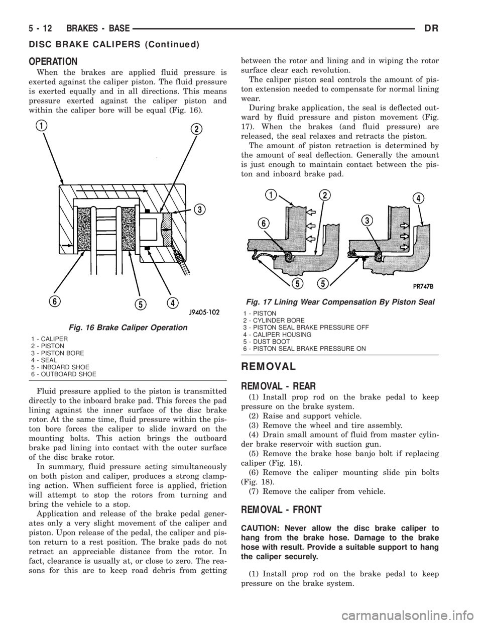
OPERATION
When the brakes are applied fluid pressure is
exerted against the caliper piston. The fluid pressure
is exerted equally and in all directions. This means
pressure exerted against the caliper piston and
within the caliper bore will be equal (Fig. 16).
Fluid pressure applied to the piston is transmitted
directly to the inboard brake pad. This forces the pad
lining against the inner surface of the disc brake
rotor. At the same time, fluid pressure within the pis-
ton bore forces the caliper to slide inward on the
mounting bolts. This action brings the outboard
brake pad lining into contact with the outer surface
of the disc brake rotor.
In summary, fluid pressure acting simultaneously
on both piston and caliper, produces a strong clamp-
ing action. When sufficient force is applied, friction
will attempt to stop the rotors from turning and
bring the vehicle to a stop.
Application and release of the brake pedal gener-
ates only a very slight movement of the caliper and
piston. Upon release of the pedal, the caliper and pis-
ton return to a rest position. The brake pads do not
retract an appreciable distance from the rotor. In
fact, clearance is usually at, or close to zero. The rea-
sons for this are to keep road debris from gettingbetween the rotor and lining and in wiping the rotor
surface clear each revolution.
The caliper piston seal controls the amount of pis-
ton extension needed to compensate for normal lining
wear.
During brake application, the seal is deflected out-
ward by fluid pressure and piston movement (Fig.
17). When the brakes (and fluid pressure) are
released, the seal relaxes and retracts the piston.
The amount of piston retraction is determined by
the amount of seal deflection. Generally the amount
is just enough to maintain contact between the pis-
ton and inboard brake pad.
REMOVAL
REMOVAL - REAR
(1) Install prop rod on the brake pedal to keep
pressure on the brake system.
(2) Raise and support vehicle.
(3) Remove the wheel and tire assembly.
(4) Drain small amount of fluid from master cylin-
der brake reservoir with suction gun.
(5) Remove the brake hose banjo bolt if replacing
caliper (Fig. 18).
(6) Remove the caliper mounting slide pin bolts
(Fig. 18).
(7) Remove the caliper from vehicle.
REMOVAL - FRONT
CAUTION: Never allow the disc brake caliper to
hang from the brake hose. Damage to the brake
hose with result. Provide a suitable support to hang
the caliper securely.
(1) Install prop rod on the brake pedal to keep
pressure on the brake system.
Fig. 16 Brake Caliper Operation
1 - CALIPER
2 - PISTON
3 - PISTON BORE
4 - SEAL
5 - INBOARD SHOE
6 - OUTBOARD SHOE
Fig. 17 Lining Wear Compensation By Piston Seal
1 - PISTON
2 - CYLINDER BORE
3 - PISTON SEAL BRAKE PRESSURE OFF
4 - CALIPER HOUSING
5 - DUST BOOT
6 - PISTON SEAL BRAKE PRESSURE ON
5 - 12 BRAKES - BASEDR
DISC BRAKE CALIPERS (Continued)
Page 243 of 2895
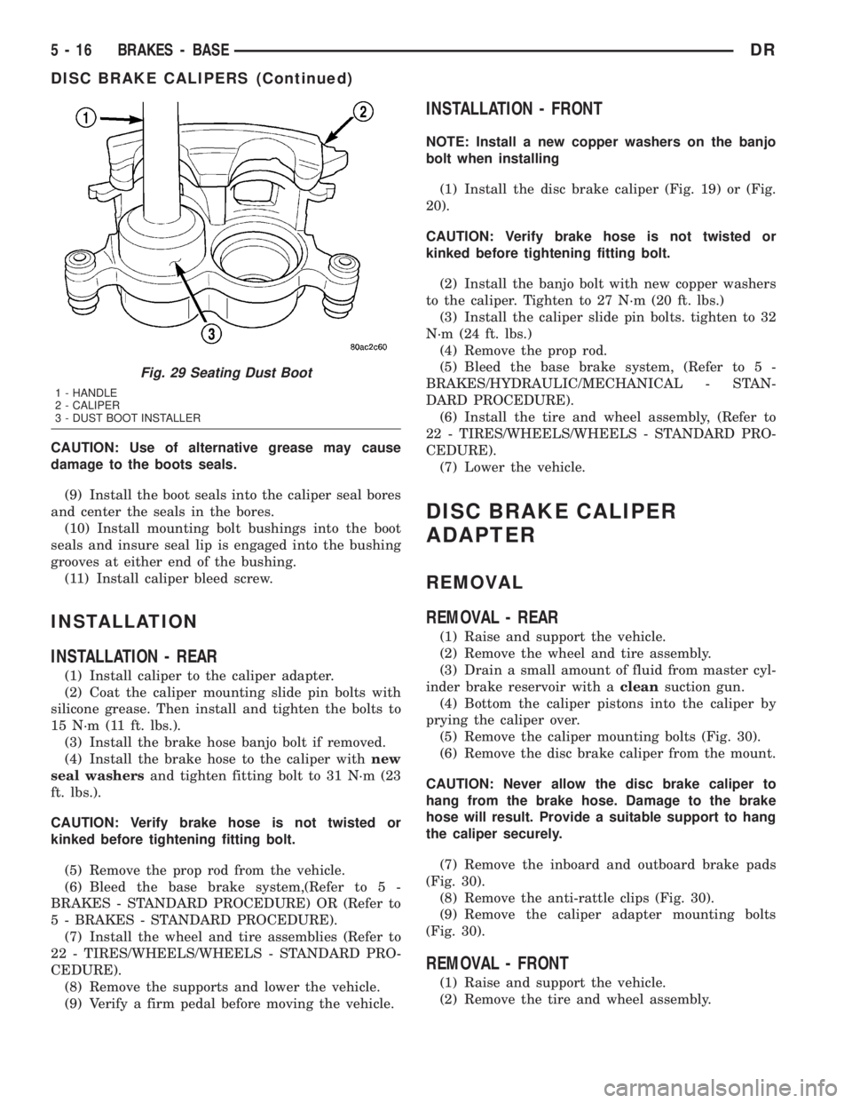
CAUTION: Use of alternative grease may cause
damage to the boots seals.
(9) Install the boot seals into the caliper seal bores
and center the seals in the bores.
(10) Install mounting bolt bushings into the boot
seals and insure seal lip is engaged into the bushing
grooves at either end of the bushing.
(11) Install caliper bleed screw.
INSTALLATION
INSTALLATION - REAR
(1) Install caliper to the caliper adapter.
(2) Coat the caliper mounting slide pin bolts with
silicone grease. Then install and tighten the bolts to
15 N´m (11 ft. lbs.).
(3) Install the brake hose banjo bolt if removed.
(4) Install the brake hose to the caliper withnew
seal washersand tighten fitting bolt to 31 N´m (23
ft. lbs.).
CAUTION: Verify brake hose is not twisted or
kinked before tightening fitting bolt.
(5) Remove the prop rod from the vehicle.
(6) Bleed the base brake system,(Refer to 5 -
BRAKES - STANDARD PROCEDURE) OR (Refer to
5 - BRAKES - STANDARD PROCEDURE).
(7) Install the wheel and tire assemblies (Refer to
22 - TIRES/WHEELS/WHEELS - STANDARD PRO-
CEDURE).
(8) Remove the supports and lower the vehicle.
(9) Verify a firm pedal before moving the vehicle.
INSTALLATION - FRONT
NOTE: Install a new copper washers on the banjo
bolt when installing
(1) Install the disc brake caliper (Fig. 19) or (Fig.
20).
CAUTION: Verify brake hose is not twisted or
kinked before tightening fitting bolt.
(2) Install the banjo bolt with new copper washers
to the caliper. Tighten to 27 N´m (20 ft. lbs.)
(3) Install the caliper slide pin bolts. tighten to 32
N´m (24 ft. lbs.)
(4) Remove the prop rod.
(5) Bleed the base brake system, (Refer to 5 -
BRAKES/HYDRAULIC/MECHANICAL - STAN-
DARD PROCEDURE).
(6) Install the tire and wheel assembly, (Refer to
22 - TIRES/WHEELS/WHEELS - STANDARD PRO-
CEDURE).
(7) Lower the vehicle.
DISC BRAKE CALIPER
ADAPTER
REMOVAL
REMOVAL - REAR
(1) Raise and support the vehicle.
(2) Remove the wheel and tire assembly.
(3) Drain a small amount of fluid from master cyl-
inder brake reservoir with acleansuction gun.
(4) Bottom the caliper pistons into the caliper by
prying the caliper over.
(5) Remove the caliper mounting bolts (Fig. 30).
(6) Remove the disc brake caliper from the mount.
CAUTION: Never allow the disc brake caliper to
hang from the brake hose. Damage to the brake
hose will result. Provide a suitable support to hang
the caliper securely.
(7) Remove the inboard and outboard brake pads
(Fig. 30).
(8) Remove the anti-rattle clips (Fig. 30).
(9) Remove the caliper adapter mounting bolts
(Fig. 30).
REMOVAL - FRONT
(1) Raise and support the vehicle.
(2) Remove the tire and wheel assembly.
Fig. 29 Seating Dust Boot
1 - HANDLE
2 - CALIPER
3 - DUST BOOT INSTALLER
5 - 16 BRAKES - BASEDR
DISC BRAKE CALIPERS (Continued)
Page 244 of 2895
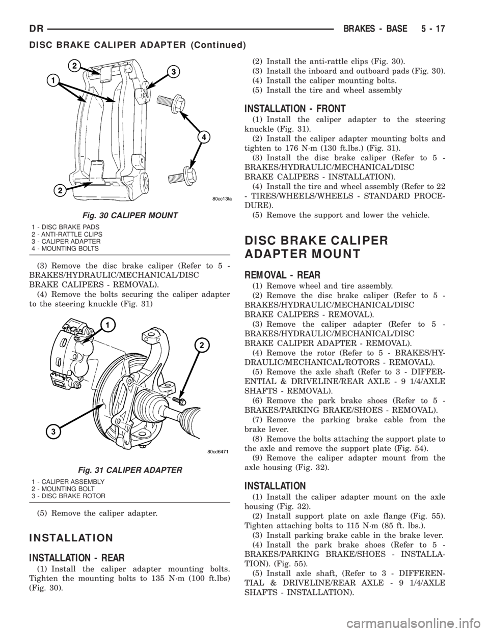
(3) Remove the disc brake caliper (Refer to 5 -
BRAKES/HYDRAULIC/MECHANICAL/DISC
BRAKE CALIPERS - REMOVAL).
(4) Remove the bolts securing the caliper adapter
to the steering knuckle (Fig. 31)
(5) Remove the caliper adapter.
INSTALLATION
INSTALLATION - REAR
(1) Install the caliper adapter mounting bolts.
Tighten the mounting bolts to 135 N´m (100 ft.lbs)
(Fig. 30).(2) Install the anti-rattle clips (Fig. 30).
(3) Install the inboard and outboard pads (Fig. 30).
(4) Install the caliper mounting bolts.
(5) Install the tire and wheel assembly
INSTALLATION - FRONT
(1) Install the caliper adapter to the steering
knuckle (Fig. 31).
(2) Install the caliper adapter mounting bolts and
tighten to 176 N´m (130 ft.lbs.) (Fig. 31).
(3) Install the disc brake caliper (Refer to 5 -
BRAKES/HYDRAULIC/MECHANICAL/DISC
BRAKE CALIPERS - INSTALLATION).
(4) Install the tire and wheel assembly (Refer to 22
- TIRES/WHEELS/WHEELS - STANDARD PROCE-
DURE).
(5) Remove the support and lower the vehicle.
DISC BRAKE CALIPER
ADAPTER MOUNT
REMOVAL - REAR
(1) Remove wheel and tire assembly.
(2) Remove the disc brake caliper (Refer to 5 -
BRAKES/HYDRAULIC/MECHANICAL/DISC
BRAKE CALIPERS - REMOVAL).
(3) Remove the caliper adapter (Refer to 5 -
BRAKES/HYDRAULIC/MECHANICAL/DISC
BRAKE CALIPER ADAPTER - REMOVAL).
(4) Remove the rotor (Refer to 5 - BRAKES/HY-
DRAULIC/MECHANICAL/ROTORS - REMOVAL).
(5) Remove the axle shaft (Refer to 3 - DIFFER-
ENTIAL & DRIVELINE/REAR AXLE - 9 1/4/AXLE
SHAFTS - REMOVAL).
(6) Remove the park brake shoes (Refer to 5 -
BRAKES/PARKING BRAKE/SHOES - REMOVAL).
(7) Remove the parking brake cable from the
brake lever.
(8) Remove the bolts attaching the support plate to
the axle and remove the support plate (Fig. 54).
(9) Remove the caliper adapter mount from the
axle housing (Fig. 32).
INSTALLATION
(1) Install the caliper adapter mount on the axle
housing (Fig. 32).
(2) Install support plate on axle flange (Fig. 55).
Tighten attaching bolts to 115 N´m (85 ft. lbs.).
(3) Install parking brake cable in the brake lever.
(4) Install the park brake shoes (Refer to 5 -
BRAKES/PARKING BRAKE/SHOES - INSTALLA-
TION). (Fig. 55).
(5) Install axle shaft, (Refer to 3 - DIFFEREN-
TIAL & DRIVELINE/REAR AXLE - 9 1/4/AXLE
SHAFTS - INSTALLATION).
Fig. 30 CALIPER MOUNT
1 - DISC BRAKE PADS
2 - ANTI-RATTLE CLIPS
3 - CALIPER ADAPTER
4 - MOUNTING BOLTS
Fig. 31 CALIPER ADAPTER
1 - CALIPER ASSEMBLY
2 - MOUNTING BOLT
3 - DISC BRAKE ROTOR
DRBRAKES - BASE 5 - 17
DISC BRAKE CALIPER ADAPTER (Continued)
Page 256 of 2895
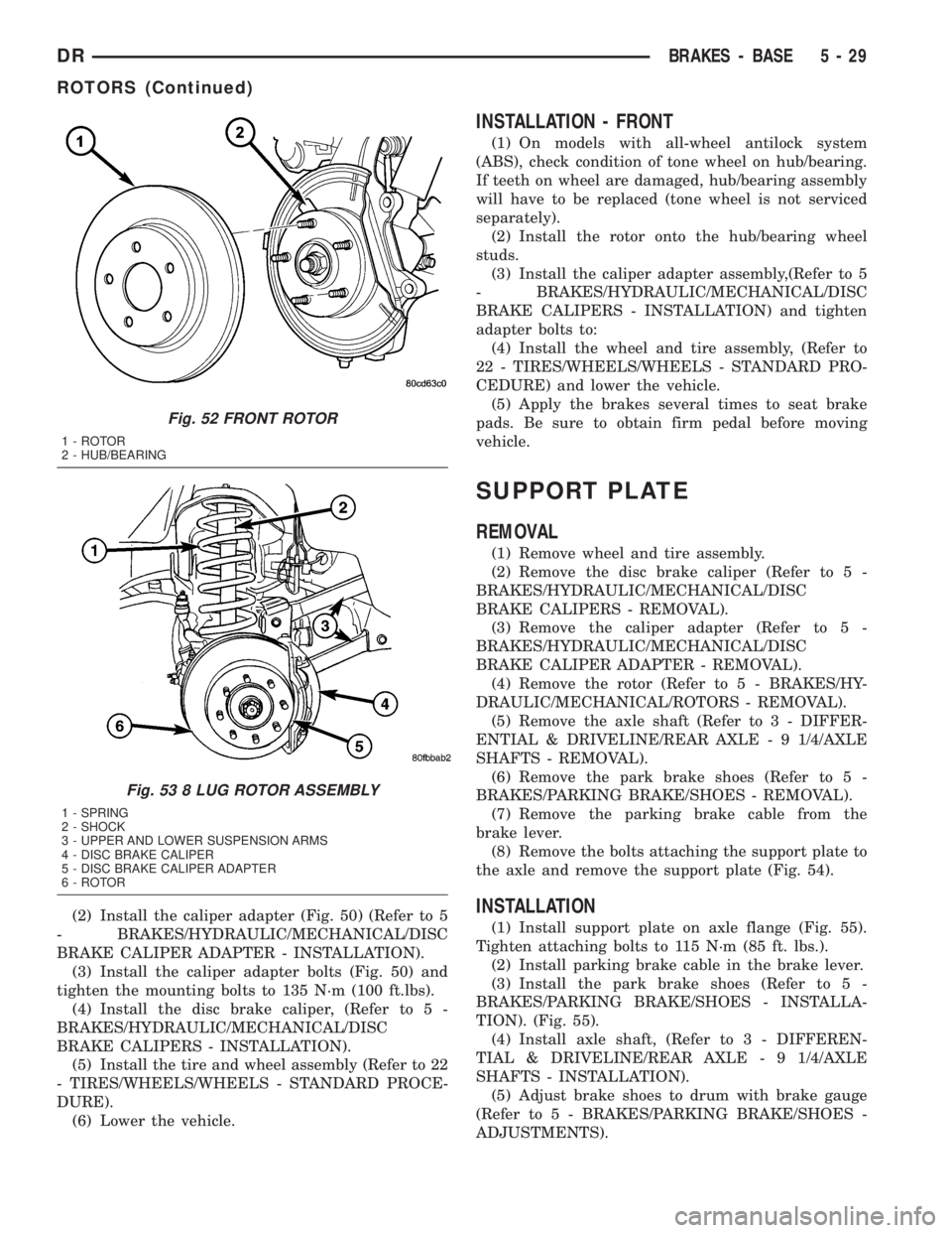
(2) Install the caliper adapter (Fig. 50) (Refer to 5
- BRAKES/HYDRAULIC/MECHANICAL/DISC
BRAKE CALIPER ADAPTER - INSTALLATION).
(3) Install the caliper adapter bolts (Fig. 50) and
tighten the mounting bolts to 135 N´m (100 ft.lbs).
(4) Install the disc brake caliper, (Refer to 5 -
BRAKES/HYDRAULIC/MECHANICAL/DISC
BRAKE CALIPERS - INSTALLATION).
(5) Install the tire and wheel assembly (Refer to 22
- TIRES/WHEELS/WHEELS - STANDARD PROCE-
DURE).
(6) Lower the vehicle.
INSTALLATION - FRONT
(1) On models with all-wheel antilock system
(ABS), check condition of tone wheel on hub/bearing.
If teeth on wheel are damaged, hub/bearing assembly
will have to be replaced (tone wheel is not serviced
separately).
(2) Install the rotor onto the hub/bearing wheel
studs.
(3) Install the caliper adapter assembly,(Refer to 5
- BRAKES/HYDRAULIC/MECHANICAL/DISC
BRAKE CALIPERS - INSTALLATION) and tighten
adapter bolts to:
(4) Install the wheel and tire assembly, (Refer to
22 - TIRES/WHEELS/WHEELS - STANDARD PRO-
CEDURE) and lower the vehicle.
(5) Apply the brakes several times to seat brake
pads. Be sure to obtain firm pedal before moving
vehicle.
SUPPORT PLATE
REMOVAL
(1) Remove wheel and tire assembly.
(2) Remove the disc brake caliper (Refer to 5 -
BRAKES/HYDRAULIC/MECHANICAL/DISC
BRAKE CALIPERS - REMOVAL).
(3) Remove the caliper adapter (Refer to 5 -
BRAKES/HYDRAULIC/MECHANICAL/DISC
BRAKE CALIPER ADAPTER - REMOVAL).
(4) Remove the rotor (Refer to 5 - BRAKES/HY-
DRAULIC/MECHANICAL/ROTORS - REMOVAL).
(5) Remove the axle shaft (Refer to 3 - DIFFER-
ENTIAL & DRIVELINE/REAR AXLE - 9 1/4/AXLE
SHAFTS - REMOVAL).
(6) Remove the park brake shoes (Refer to 5 -
BRAKES/PARKING BRAKE/SHOES - REMOVAL).
(7) Remove the parking brake cable from the
brake lever.
(8) Remove the bolts attaching the support plate to
the axle and remove the support plate (Fig. 54).
INSTALLATION
(1) Install support plate on axle flange (Fig. 55).
Tighten attaching bolts to 115 N´m (85 ft. lbs.).
(2) Install parking brake cable in the brake lever.
(3) Install the park brake shoes (Refer to 5 -
BRAKES/PARKING BRAKE/SHOES - INSTALLA-
TION). (Fig. 55).
(4) Install axle shaft, (Refer to 3 - DIFFEREN-
TIAL & DRIVELINE/REAR AXLE - 9 1/4/AXLE
SHAFTS - INSTALLATION).
(5) Adjust brake shoes to drum with brake gauge
(Refer to 5 - BRAKES/PARKING BRAKE/SHOES -
ADJUSTMENTS).
Fig. 52 FRONT ROTOR
1 - ROTOR
2 - HUB/BEARING
Fig. 53 8 LUG ROTOR ASSEMBLY
1 - SPRING
2 - SHOCK
3 - UPPER AND LOWER SUSPENSION ARMS
4 - DISC BRAKE CALIPER
5 - DISC BRAKE CALIPER ADAPTER
6 - ROTOR
DRBRAKES - BASE 5 - 29
ROTORS (Continued)
Page 260 of 2895
(6) Install the right cable to the front cable.
(7) Adjust the brake cable at the equalizer and
using the adjuster nut.
INSTALLATION - LEFT REAR CABLE
(1) Install the brake cable to the brake lever (Fig.
61).
(2) Install the brake cable to the frame bracket.
(3) Install the left brake cable to the equalizer.
(4) Adjust the brake cable at the equalizer and
adjuster nut.
SHOES
REMOVAL
(1) Raise and support the vehicle.
(2) Remove the tire and wheel assembly.
(3) Remove the disc brake caliper,(Refer to 5 -
BRAKES/HYDRAULIC/MECHANICAL/DISC
BRAKE CALIPERS - REMOVAL).
(4) Remove the disc brake rotor, (Refer to 5 -
BRAKES/HYDRAULIC/MECHANICAL/ROTORS -
REMOVAL).
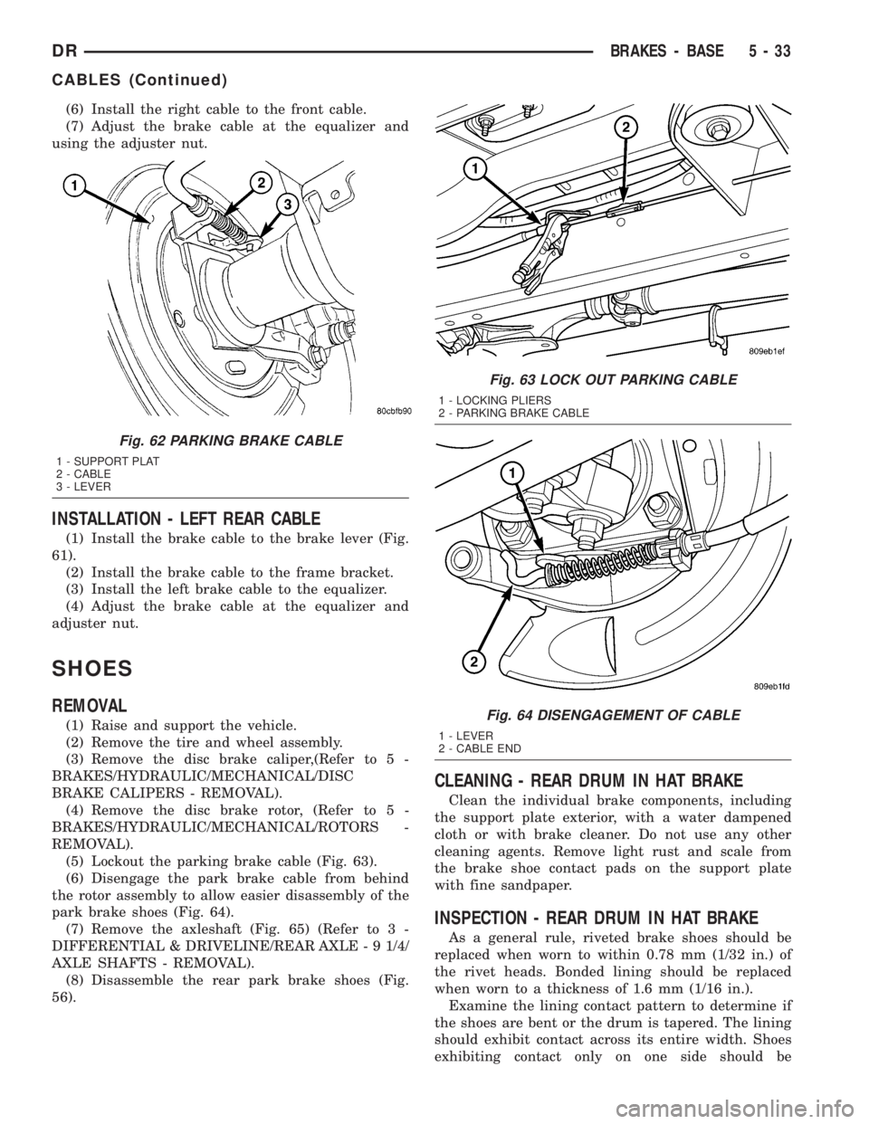
(5) Lockout the parking brake cable (Fig. 63).
(6) Disengage the park brake cable from behind
the rotor assembly to allow easier disassembly of the
park brake shoes (Fig. 64).
(7) Remove the axleshaft (Fig. 65) (Refer to 3 -
DIFFERENTIAL & DRIVELINE/REAR AXLE - 9 1/4/
AXLE SHAFTS - REMOVAL).
(8) Disassemble the rear park brake shoes (Fig.
56).
CLEANING - REAR DRUM IN HAT BRAKE
Clean the individual brake components, including
the support plate exterior, with a water dampened
cloth or with brake cleaner. Do not use any other
cleaning agents. Remove light rust and scale from
the brake shoe contact pads on the support plate
with fine sandpaper.
INSPECTION - REAR DRUM IN HAT BRAKE
As a general rule, riveted brake shoes should be
replaced when worn to within 0.78 mm (1/32 in.) of
the rivet heads. Bonded lining should be replaced
when worn to a thickness of 1.6 mm (1/16 in.).
Examine the lining contact pattern to determine if
the shoes are bent or the drum is tapered. The lining
should exhibit contact across its entire width. Shoes
exhibiting contact only on one side should be
Fig. 62 PARKING BRAKE CABLE
1 - SUPPORT PLAT
2 - CABLE
3 - LEVER
Fig. 63 LOCK OUT PARKING CABLE
1 - LOCKING PLIERS
2 - PARKING BRAKE CABLE
Fig. 64 DISENGAGEMENT OF CABLE
1 - LEVER
2 - CABLE END
DRBRAKES - BASE 5 - 33
CABLES (Continued)
Page 261 of 2895
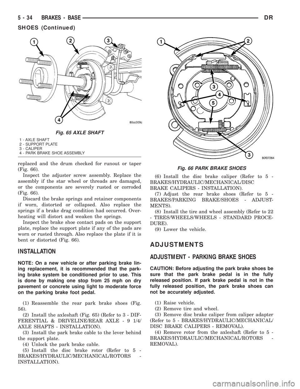
replaced and the drum checked for runout or taper
(Fig. 66).
Inspect the adjuster screw assembly. Replace the
assembly if the star wheel or threads are damaged,
or the components are severely rusted or corroded
(Fig. 66).
Discard the brake springs and retainer components
if worn, distorted or collapsed. Also replace the
springs if a brake drag condition had occurred. Over-
heating will distort and weaken the springs.
Inspect the brake shoe contact pads on the support
plate, replace the support plate if any of the pads are
worn or rusted through. Also replace the plate if it is
bent or distorted (Fig. 66).
INSTALLATION
NOTE: On a new vehicle or after parking brake lin-
ing replacement, it is recommended that the park-
ing brake system be conditioned prior to use. This
is done by making one stop from 25 mph on dry
pavement or concrete using light to moderate force
on the parking brake foot pedal.
(1) Reassemble the rear park brake shoes (Fig.
56).
(2) Install the axleshaft (Fig. 65) (Refer to 3 - DIF-
FERENTIAL & DRIVELINE/REAR AXLE - 9 1/4/
AXLE SHAFTS - INSTALLATION).
(3) Install the park brake cable to the lever behind
the support plate.
(4) Unlock the park brake cable.
(5) Install the disc brake rotor (Refer to 5 -
BRAKES/HYDRAULIC/MECHANICAL/ROTORS -
INSTALLATION).(6) Install the disc brake caliper (Refer to 5 -
BRAKES/HYDRAULIC/MECHANICAL/DISC
BRAKE CALIPERS - INSTALLATION).
(7) Adjust the rear brake shoes (Refer to 5 -
BRAKES/PARKING BRAKE/SHOES - ADJUST-
MENTS).
(8) Install the tire and wheel assembly (Refer to 22
- TIRES/WHEELS/WHEELS - STANDARD PROCE-
DURE).
(9) Lower the vehicle.
ADJUSTMENTS
ADJUSTMENT - PARKING BRAKE SHOES
CAUTION: Before adjusting the park brake shoes be
sure that the park brake pedal is in the fully
released position. If park brake pedal is not in the
fully released position, the park brake shoes can
not be accurately adjusted.
(1) Raise vehicle.
(2) Remove tire and wheel.
(3) Remove disc brake caliper from caliper adapter
(Refer to 5 - BRAKES/HYDRAULIC/MECHANICAL/
DISC BRAKE CALIPERS - REMOVAL).
(4) Remove rotor from the axleshaft (Refer to 5 -
BRAKES/HYDRAULIC/MECHANICAL/ROTORS -
REMOVAL).
Fig. 65 AXLE SHAFT
1 - AXLE SHAFT
2 - SUPPORT PLATE
3 - CALIPER
4 - PARK BRAKE SHOE ASSEMBLY
Fig. 66 PARK BRAKE SHOES
5 - 34 BRAKES - BASEDR
SHOES (Continued)