door lock DODGE RAM 2003 Service Repair Manual
[x] Cancel search | Manufacturer: DODGE, Model Year: 2003, Model line: RAM, Model: DODGE RAM 2003Pages: 2895, PDF Size: 83.15 MB
Page 366 of 2895
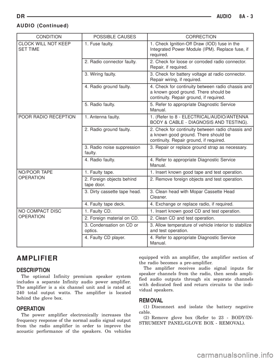
CONDITION POSSIBLE CAUSES CORRECTION
CLOCK WILL NOT KEEP
SET TIME1. Fuse faulty. 1. Check Ignition-Off Draw (IOD) fuse in the
Integrated Power Module (IPM). Replace fuse, if
required.
2. Radio connector faulty. 2. Check for loose or corroded radio connector.
Repair, if required.
3. Wiring faulty. 3. Check for battery voltage at radio connector.
Repair wiring, if required.
4. Radio ground faulty. 4. Check for continuity between radio chassis and
a known good ground. There should be
continuity. Repair ground, if required.
5. Radio faulty. 5. Refer to appropriate Diagnostic Service
Manual.
POOR RADIO RECEPTION 1. Antenna faulty. 1. (Refer to 8 - ELECTRICAL/AUDIO/ANTENNA
BODY & CABLE - DIAGNOSIS AND TESTING).
2. Radio ground faulty. 2. Check for continuity between radio chassis and
a known good ground. There should be
continuity. Repair ground, if required.
3. Radio noise suppression
faulty.3. Repair or replace ground strap as necessary.
4. Radio faulty. 4. Refer to appropriate Diagnostic Service
Manual.
NO/POOR TAPE
OPERATION1. Faulty tape. 1. Insert known good tape and test operation.
2. Foreign objects behind
tape door.2. Remove foreign objects and test operation.
3. Dirty cassette tape head. 3. Clean head with Mopar Cassette Head
Cleaner.
4. Faulty tape deck. 4. Exchange or replace radio, if required.
NO COMPACT DISC
OPERATION1. Faulty CD. 1. Insert known good CD and test operation.
2. Foreign material on CD. 2. Clean CD and test operation.
3. Condensation on CD or
optics.3. Allow temperature of vehicle interior to stabilize
and test operation.
4. Faulty CD player. 4. Refer to appropriate Diagnostic Service
Manual.
AMPLIFIER
DESCRIPTION
The optional Infinity premium speaker system
includes a separate Infinity audio power amplifier.
The amplifier is a six channel unit and is rated at
240 total output watts. The amplifier is located
behind the glove box.
OPERATION
The power amplifier electronically increases the
frequency response of the normal audio signal output
from the radio amplifier in order to improve the
acoustic performance of the speakers. On vehiclesequipped with an amplifier, the amplifier section of
the radio becomes a pre-amplifier.
The amplifier receives audio signal inputs for
speaker channels from the radio, then sends ampli-
fied audio outputs through six separate channels
with dedicated feed and return circuits to the indi-
vidual speakers.
REMOVAL
(1) Disconnect and isolate the battery negative
cable.
(2) Remove glove box (Refer to 23 - BODY/IN-
STRUMENT PANEL/GLOVE BOX - REMOVAL).
DRAUDIO 8A - 3
AUDIO (Continued)
Page 369 of 2895
antenna body to fender mating surfaces and tighten
the antenna cap nut to specifications.
(4) Check the resistance again with an ohmmeter.
If the resistance is still more then one ohm, replace
the faulty antenna body and cable.
REMOVAL
(1) Disconnect and isolate the battery negative
cable.
(2) Remove the right side kick panel.
(3) Disconnect antenna body cable from instru-
ment panel cable.
(4) Securely tie a suitable length of cord or twine
to the antenna half of the coaxial cable connector.
This cord will be used to pull the cable back into
position during installation.
(5) Remove the antenna mast.
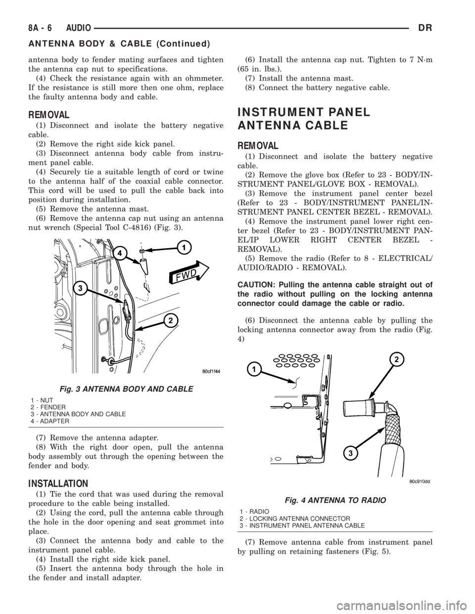
(6) Remove the antenna cap nut using an antenna
nut wrench (Special Tool C-4816) (Fig. 3).
(7) Remove the antenna adapter.
(8) With the right door open, pull the antenna
body assembly out through the opening between the
fender and body.
INSTALLATION
(1) Tie the cord that was used during the removal
procedure to the cable being installed.
(2) Using the cord, pull the antenna cable through
the hole in the door opening and seat grommet into
place.
(3) Connect the antenna body and cable to the
instrument panel cable.
(4) Install the right side kick panel.
(5) Insert the antenna body through the hole in
the fender and install adapter.(6) Install the antenna cap nut. Tighten to 7 N´m
(65 in. lbs.).
(7) Install the antenna mast.
(8) Connect the battery negative cable.
INSTRUMENT PANEL
ANTENNA CABLE
REMOVAL
(1) Disconnect and isolate the battery negative
cable.
(2) Remove the glove box (Refer to 23 - BODY/IN-
STRUMENT PANEL/GLOVE BOX - REMOVAL).
(3) Remove the instrument panel center bezel
(Refer to 23 - BODY/INSTRUMENT PANEL/IN-
STRUMENT PANEL CENTER BEZEL - REMOVAL).
(4) Remove the instrument panel lower right cen-
ter bezel (Refer to 23 - BODY/INSTRUMENT PAN-
EL/IP LOWER RIGHT CENTER BEZEL -
REMOVAL).
(5) Remove the radio (Refer to 8 - ELECTRICAL/
AUDIO/RADIO - REMOVAL).
CAUTION: Pulling the antenna cable straight out of
the radio without pulling on the locking antenna
connector could damage the cable or radio.
(6) Disconnect the antenna cable by pulling the
locking antenna connector away from the radio (Fig.
4)
(7) Remove antenna cable from instrument panel
by pulling on retaining fasteners (Fig. 5).
Fig. 3 ANTENNA BODY AND CABLE
1 - NUT
2 - FENDER
3 - ANTENNA BODY AND CABLE
4 - ADAPTER
Fig. 4 ANTENNA TO RADIO
1 - RADIO
2 - LOCKING ANTENNA CONNECTOR
3 - INSTRUMENT PANEL ANTENNA CABLE
8A - 6 AUDIODR
ANTENNA BODY & CABLE (Continued)
Page 380 of 2895
CHIME/BUZZER
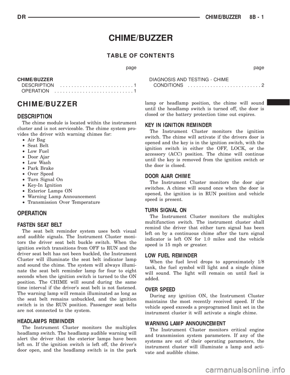
TABLE OF CONTENTS
page page
CHIME/BUZZER
DESCRIPTION..........................1
OPERATION............................1DIAGNOSIS AND TESTING - CHIME
CONDITIONS..........................2
CHIME/BUZZER
DESCRIPTION
The chime module is located within the instrument
cluster and is not serviceable. The chime system pro-
vides the driver with warning chimes for:
²Air Bag
²Seat Belt
²Low Fuel
²Door Ajar
²Low Wash
²Park Brake
²Over Speed
²Turn Signal On
²Key-In Ignition
²Exterior Lamps ON
²Warning Lamp Announcement
²Transmission Over Temperature
OPERATION
FASTEN SEAT BELT
The seat belt reminder system uses both visual
and audible signals. The Instrument Cluster moni-
tors the driver seat belt buckle switch. When the
ignition switch transitions from OFF to RUN and the
driver seat belt has not been buckled, the Instrument
Cluster will illuminate the seat belt indicator lamp
and sound the chime. The system will always illumi-
nate the seat belt reminder lamp for four to eight
seconds when the ignition switch is turned to the ON
position. The CHIME will sound during the same
time interval if the driver's seat belt is not fastened.
The warning lamp will remain illuminated as long as
the seat belt remains unbuckled, and the ignition
switch is in the RUN position. Passenger seat belts
are not connected to the system.
HEADLAMPS REMINDER
The Instrument Cluster monitors the multiplex
headlamp switch. The headlamp audible warning will
alert the driver that the exterior lamps have been
left on. If the ignition switch is left off, the driver's
door open, and the headlamp switch is in the parklamp or headlamp position, the chime will sound
until the headlamp switch is turned off, the door is
closed or the battery protection time out expires.
KEY IN IGNITION REMINDER
The Instrument Cluster monitors the ignition
switch. The chime will activate if the drivers door is
opened and the key is in the ignition switch, with the
ignition switch in either the OFF, LOCK, or the
accessory (ACC) position. The chime will continue
until the key is removed from the ignition switch or
the door is closed.
DOOR AJAR CHIME
The Instrument Cluster monitors the door ajar
switches. A chime will sound once when the door is
opened, the ignition is in RUN position and vehicle
speed is present.
TURN SIGNAL ON
The Instrument Cluster monitors the multiplex
multifunction switch. The instrument cluster shall
remind the driver that either turn signal has been
left on by a continuous chime after the turn signal
indicator is left ON for 1.0 miles and the vehicle
speed is 15 mph or greater.
LOW FUEL REMINDER
When the fuel level drops to approximately 1/8
tank, the fuel symbol will light and a single chime
will sound. The light will remain on until fuel is
added.
OVER SPEED
During any ignition ON, the Instrument Cluster
maintains the most recently received speed. If the
vehicle speed exceeds a preprogramed limit set in the
instrument cluster it will activate a single chime.
WARNING LAMP ANNOUNCEMENT
The Instrument Cluster monitors critical engine
and transmission system parameters. If any of the
systems are out of their operating parameters, the
instrument cluster will illuminate a lamp and acti-
vate and audible chime.
DRCHIME/BUZZER 8B - 1
Page 416 of 2895
Turn on the headlamps for fifteen seconds, then
allow up to five minutes for the battery voltage to
stabilize.
(2) Disconnect and isolate both battery cables, neg-
ative cable first.
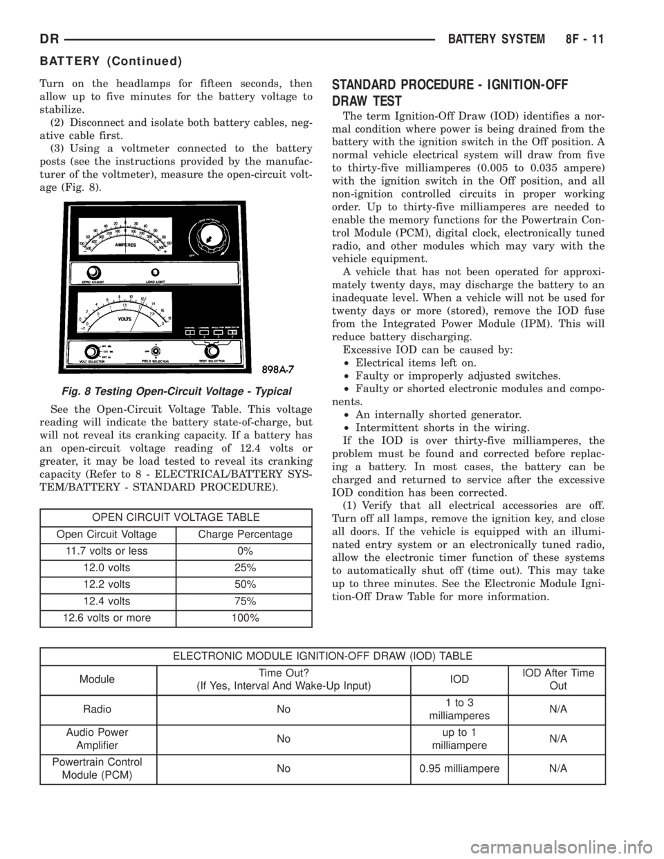
(3) Using a voltmeter connected to the battery
posts (see the instructions provided by the manufac-
turer of the voltmeter), measure the open-circuit volt-
age (Fig. 8).
See the Open-Circuit Voltage Table. This voltage
reading will indicate the battery state-of-charge, but
will not reveal its cranking capacity. If a battery has
an open-circuit voltage reading of 12.4 volts or
greater, it may be load tested to reveal its cranking
capacity (Refer to 8 - ELECTRICAL/BATTERY SYS-
TEM/BATTERY - STANDARD PROCEDURE).
OPEN CIRCUIT VOLTAGE TABLE
Open Circuit Voltage Charge Percentage
11.7 volts or less 0%
12.0 volts 25%
12.2 volts 50%
12.4 volts 75%
12.6 volts or more 100%
STANDARD PROCEDURE - IGNITION-OFF
DRAW TEST
The term Ignition-Off Draw (IOD) identifies a nor-
mal condition where power is being drained from the
battery with the ignition switch in the Off position. A
normal vehicle electrical system will draw from five
to thirty-five milliamperes (0.005 to 0.035 ampere)
with the ignition switch in the Off position, and all
non-ignition controlled circuits in proper working
order. Up to thirty-five milliamperes are needed to
enable the memory functions for the Powertrain Con-
trol Module (PCM), digital clock, electronically tuned
radio, and other modules which may vary with the
vehicle equipment.
A vehicle that has not been operated for approxi-
mately twenty days, may discharge the battery to an
inadequate level. When a vehicle will not be used for
twenty days or more (stored), remove the IOD fuse
from the Integrated Power Module (IPM). This will
reduce battery discharging.
Excessive IOD can be caused by:
²Electrical items left on.
²Faulty or improperly adjusted switches.
²Faulty or shorted electronic modules and compo-
nents.
²An internally shorted generator.
²Intermittent shorts in the wiring.
If the IOD is over thirty-five milliamperes, the
problem must be found and corrected before replac-
ing a battery. In most cases, the battery can be
charged and returned to service after the excessive
IOD condition has been corrected.
(1) Verify that all electrical accessories are off.
Turn off all lamps, remove the ignition key, and close
all doors. If the vehicle is equipped with an illumi-
nated entry system or an electronically tuned radio,
allow the electronic timer function of these systems
to automatically shut off (time out). This may take
up to three minutes. See the Electronic Module Igni-
tion-Off Draw Table for more information.
ELECTRONIC MODULE IGNITION-OFF DRAW (IOD) TABLE
ModuleTime Out?
(If Yes, Interval And Wake-Up Input)IODIOD After Time
Out
Radio No1to3
milliamperesN/A
Audio Power
AmplifierNoup to 1
milliampereN/A
Powertrain Control
Module (PCM)No 0.95 milliampere N/A
Fig. 8 Testing Open-Circuit Voltage - Typical
DRBATTERY SYSTEM 8F - 11
BATTERY (Continued)
Page 496 of 2895
molded plastic cluster housing serves as the carrier
for the cluster circuit board and circuitry, the cluster
connector receptacles, the RKE interface connector,
the gauges, a Light Emitting Diode (LED) for each
cluster indicator, two VFD units, an audible tone
generator, the cluster overlay, the gauge pointers, the
odometer/trip odometer switch and the switch button.
The cluster overlay is a laminated plastic unit. The
dark, visible, outer surface of the overlay is marked
with all of the gauge dial faces and graduations, but
this layer is also translucent. The darkness of this
outer layer prevents the cluster from appearing clut-
tered or busy by concealing the cluster indicators
that are not illuminated, while the translucence of
this layer allows those indicators and icons that are
illuminated to be readily visible. The underlying
layer of the overlay is opaque and allows light from
the LED for each of the various indicators and the
incandescent illumination lamps behind it to be visi-
ble through the outer layer of the overlay only
through predetermined stencil-like cutouts. A rectan-
gular opening in the overlay at the base of both the
speedometer and tachometer dial faces has a smoked
clear lens through which the illuminated VFD units
can be viewed.
Several versions of the EMIC module are offered
on this model. These versions accommodate all of the
variations of optional equipment and regulatory
requirements for the various markets in which the
vehicle will be offered. The microprocessor-based
EMIC utilizes integrated circuitry and information
carried on the Programmable Communications Inter-
face (PCI) data bus network along with several hard
wired analog and multiplexed inputs to monitor sen-
sors and switches throughout the vehicle. In response
to those inputs, the internal circuitry and program-
ming of the EMIC allow it to control and integrate
many electronic functions and features of the vehicle
through both hard wired outputs and the transmis-
sion of electronic message outputs to other electronic
modules in the vehicle over the PCI data bus. (Refer
to 8 - ELECTRICAL/ELECTRONIC CONTROL
MODULES/COMMUNICATION - DESCRIPTION -
PCI BUS).
Besides typical instrument cluster gauge and indi-
cator support, the electronic functions and features
that the EMIC supports or controls include the fol-
lowing:
²Audible Warnings- The EMIC electronic cir-
cuit board is equipped with an audible tone generator
and programming that allows it to provide various
audible alerts to the vehicle operator, including
chime tones and beep tones. An electromechanical
relay is also soldered onto the circuit board to pro-
duce audible clicks that emulate the sound of a con-
ventional turn signal or hazard warning flasher.(Refer to 8 - ELECTRICAL/CHIME/BUZZER -
DESCRIPTION).
²Brake Lamp Control- The EMIC provides
electronic brake lamp request messages to the Front
Control Module (FCM) located on the Integrated
Power Module (IPM) for brake lamp control, exclud-
ing control of the Center High Mounted Stop Lamp
(CHMSL), which remains controlled by a direct hard
wired output of the brake lamp switch.
²Brake Transmission Shift Interlock Control
- The EMIC monitors inputs from the brake lamp
switch, ignition switch, and the Transmission Range
Sensor (TRS), then controls a high-side driver output
to operate the Brake Transmission Shift Interlock
(BTSI) solenoid that locks and unlocks the automatic
transmission gearshift selector lever on the steering
column.
²Cargo Lamp Control- The EMIC provides
direct control of cargo lamp operation with a load
shedding (battery saver) feature which will automat-
ically turn off the cargo lamp if it remains on after a
timed interval.
²Central Locking- The EMIC provides support
for the central locking feature of the power lock sys-
tem. This feature will lock or unlock all doors based
upon the input from the door cylinder lock switch.
Door cylinder lock switches are used only on models
equipped with the optional Vehicle Theft Security
System (VTSS).
²Door Lock Inhibit- The EMIC inhibits locking
of the doors with the power lock switch when the key
is in the ignition switch and the driver side front
door is ajar. However, operation of the door locks is
not inhibited under the same conditions when the
Lock button of the optional RKE transmitter is
depressed.
²Enhanced Accident Response- The EMIC
monitors an input from the Airbag Control Module
(ACM) and, following an airbag deployment, will
immediately disable the power lock output, unlock all
doors by activating the power unlock output, then
enables the power lock output if the power lock
switch input remains inactive for two seconds. This
feature, like all other enhanced accident response
features, is dependent upon a functional vehicle elec-
trical system following the vehicle impact event.
²Exterior Lighting Control- The EMIC pro-
vides electronic head lamp and/or park lamp request
messages to the Front Control Module (FCM) located
on the Integrated Power Module (IPM) for the appro-
priate exterior lamp control of standard head and
park lamps, as well as optional front fog lamps. This
includes support for headlamp beam selection and
the optical horn feature, also known as flash-to-pass.
²Exterior Lighting Fail-safe- In the absence of
a headlamp switch input, the EMIC will turn on the
DRINSTRUMENT CLUSTER 8J - 3
INSTRUMENT CLUSTER (Continued)
Page 497 of 2895
cluster illumination lamps and provide electronic
headlamp low beam and park lamp request messages
to the Front Control Module (FCM) located on the
Integrated Power Module (IPM) for default exterior
lamp operation. The FCM will also provide default
park lamp and headlamp low beam operation and the
EMIC will turn on the cluster illumination lamps if
there is a failure of the electronic data bus commu-
nication between the EMIC and the FCM.
²Heated Seat Control- The EMIC monitors
inputs from the ignition switch and electronic engine
speed messages from the Powertrain Control Module
(PCM) to control a high side driver output to the
heated seat switch Light Emitting Diode (LED) indi-
cators. This input allows the heated seat switches to
wake up the heated seat module if the switch is actu-
ated. The EMIC will de-energize the heated seat
switch LED indicators, which deactivates the heated
seat system, if the ignition switch is turned to any
position except On or Start, or if the engine speed
message indicates zero. (Refer to 8 - ELECTRICAL/
HEATED SEATS - DESCRIPTION).
²Interior Lamp Load Shedding- The EMIC
provides a battery saver feature which will automat-
ically turn off all interior lamps that remain on after
a timed interval of about fifteen minutes.
²Interior Lamps - Enhanced Accident
Response- The EMIC monitors inputs from the Air-
bag Control Module (ACM) and the Powertrain Con-
trol Module (PCM) to automatically turn on the
interior lighting after an airbag deployment event
ten seconds after the vehicle speed is zero. The inte-
rior lighting remains illuminated until the ignition
switch is turned to the Off position, at which time
the interior lighting returns to normal operation and
control. This feature, like all other enhanced accident
response features, is dependent upon a functional
vehicle electrical system following the vehicle impact
event.
²Interior Lighting Control- The EMIC moni-
tors inputs from the interior lighting switch, the door
ajar switches, the cargo lamp switch, the reading
lamp switches, and the Remote Keyless Entry (RKE)
module to provide courtesy lamp control. This
includes support for timed illuminated entry with
theater-style fade-to-off and courtesy illumination
defeat features.
²Lamp Out Indicator Control- The EMIC
monitors electronic lamp outage messages from the
Front Control Module (FCM) located on the Inte-
grated Power Module (IPM) in order to provide lamp
out indicator control for the headlamps (low and high
beams), turn signal lamps, and the brake lamps
(excluding CHMSL).
²Panel Lamps Dimming Control- The EMIC
provides a hard wired 12-volt Pulse-Width Modulated(PWM) output that synchronizes the dimming level
of all panel lamps dimmer controlled lamps with that
of the cluster illumination lamps.
²Parade Mode- The EMIC provides a parade
mode (also known as funeral mode) that allows all
Vacuum-Fluorescent Display (VFD) units in the vehi-
cle to be illuminated at full (daytime) intensity while
driving during daylight hours with the exterior
lamps turned on.
²Power Locks- The EMIC monitors inputs from
the power lock switches and the Remote Keyless
Entry (RKE) receiver module (optional) to provide
control of the power lock motors through high side
driver outputs to the power lock motors. This
includes support for rolling door locks (also known as
automatic door locks), automatic door unlock, a door
lock inhibit mode, and central locking (with the
optional Vehicle Theft Security System only). (Refer
to 8 - ELECTRICAL/POWER LOCKS - DESCRIP-
TION).
²Remote Keyless Entry- The EMIC supports
the optional Remote Keyless Entry (RKE) system fea-
tures, including support for the RKE Lock, Unlock
(with optional driver-door-only unlock, and unlock-
all-doors), Panic, audible chirp, optical chirp, illumi-
nated entry modes, an RKE programming mode, as
well as optional Vehicle Theft Security System
(VTSS) arming (when the proper VTSS arming con-
ditions are met) and disarming.
²Remote Radio Switch Interface- The EMIC
monitors inputs from the optional remote radio
switches and then provides the appropriate electronic
data bus messages to the radio to select the radio
operating mode, volume control, preset station scan
and station seek features.
²Rolling Door Locks- The EMIC provides sup-
port for the power lock system rolling door locks fea-
ture (also known as automatic door locks). This
feature will automatically lock all unlocked doors
each time the vehicle speed reaches twenty-four kilo-
meters-per-hour (fifteen miles-per-hour) and, follow-
ing an automatic lock event, will automatically
unlock all doors once the ignition is turned to the Off
position and the driver side front door is opened.
²Turn Signal & Hazard Warning Lamp Con-
trol- The EMIC provides electronic turn and hazard
lamp request messages to the Front Control Module
(FCM) located on the Integrated Power Module (IPM)
for turn and hazard lamp control. The EMIC also
provides an audible click at one of two rates to emu-
late normal and bulb out turn or hazard flasher oper-
ation based upon electronic lamp outage messages
from the FCM, and provides an audible turn signal
on chime warning if a turn is signalled continuously
for more than about 1.6 kilometers (one mile) and
8J - 4 INSTRUMENT CLUSTERDR
INSTRUMENT CLUSTER (Continued)
Page 498 of 2895
the vehicle speed remains greater than about twenty-
four kilometers-per-hour (fifteen miles-per-hour).
²Vacuum Fluorescent Display Synchroniza-
tion- The EMIC transmits electronic panel lamp
dimming level messages which allows all other elec-
tronic modules on the PCI data bus with Vacuum
Fluorescent Display (VFD) units to coordinate their
illumination intensity with that of the EMIC VFD
units.
²Vehicle Theft Security System- The EMIC
monitors inputs from the door cylinder lock switch-
(es), the door ajar switches, the ignition switch, and
the Remote Keyless Entry (RKE) receiver module,
then provides electronic horn and lighting request
messages to the Front Control Module (FCM) located
on the Integrated Power Module (IPM) for the appro-
priate VTSS alarm output features.
²Wiper/Washer System Control- The EMIC
provides electronic wiper and/or washer request mes-
sages to the Front Control Module (FCM) located on
the Integrated Power Module (IPM) for the appropri-
ate wiper and washer system features. (Refer to 8 -
ELECTRICAL/WIPERS/WASHERS - DESCRIP-
TION).
The EMIC houses six analog gauges and has pro-
visions for up to twenty-three indicators (Fig. 3) or
(Fig. 4). The EMIC includes the following analog
gauges:
²Coolant Temperature Gauge
²Fuel Gauge
²Oil Pressure Gauge
²Speedometer
²Tachometer
²Voltage Gauge
Some of the EMIC indicators are automatically
configured when the EMIC is connected to the vehi-
cle electrical system for compatibility with certain
optional equipment or equipment required for regula-
tory purposes in certain markets. While each EMIC
may have provisions for indicators to support every
available option, the configurable indicators will not
be functional in a vehicle that does not have the
equipment that an indicator supports. The EMIC
includes provisions for the following indicators (Fig.
3) or (Fig. 4):
²Airbag Indicator (with Airbag System only)
²Antilock Brake System (ABS) Indicator
(with ABS or Rear Wheel Anti-Lock [RWAL]
brakes only)
²Brake Indicator
²Cargo Lamp Indicator
²Check Gauges Indicator
²Cruise Indicator (with Speed Control only)
²Door Ajar Indicator
²Electronic Throttle Control (ETC) Indicator
(with 5.7L Gasoline Engine only)²Gear Selector Indicator (with Automatic
Transmission only)
²High Beam Indicator
²Lamp Out Indicator
²Low Fuel Indicator
²Malfunction Indicator Lamp (MIL)
²Overdrive-Off Indicator (with Automatic
Transmission only)
²Seatbelt Indicator
²Security Indicator (with Sentry Key Immo-
bilizer & Vehicle Theft Security Systems only)
²Service Four-Wheel Drive Indicator (with
Four-Wheel Drive only)
²Transmission Overtemp Indicator (with
Automatic Transmission only)
²Turn Signal (Right and Left) Indicators
²Upshift Indicator (with Manual Transmis-
sion only)
²Washer Fluid Indicator
²Wait-To-Start Indicator (with Diesel Engine
only)
²Water-In-Fuel Indicator (with Diesel Engine
only)
Each indicator in the EMIC, except those located
within one of the VFD units, is illuminated by a ded-
icated LED that is soldered onto the EMIC electronic
circuit board. The LED units are not available for
service replacement and, if damaged or faulty, the
entire EMIC must be replaced. Cluster illumination
is accomplished by dimmable incandescent back
lighting, which illuminates the gauges for visibility
when the exterior lighting is turned on. Each of the
incandescent bulbs is secured by an integral bulb
holder to the electronic circuit board from the back of
the cluster housing.
Hard wired circuitry connects the EMIC to the
electrical system of the vehicle. These hard wired cir-
cuits are integral to several wire harnesses, which
are routed throughout the vehicle and retained by
many different methods. These circuits may be con-
nected to each other, to the vehicle electrical system
and to the EMIC through the use of a combination of
soldered splices, splice block connectors, and many
different types of wire harness terminal connectors
and insulators. Refer to the appropriate wiring infor-
mation. The wiring information includes wiring dia-
grams, proper wire and connector repair procedures,
further details on wire harness routing and reten-
tion, as well as pin-out and location views for the
various wire harness connectors, splices and grounds.
The EMIC modules for this model are serviced only
as complete units. The EMIC module cannot be
adjusted or repaired. If a gauge, an LED indicator, a
VFD unit, the electronic circuit board, the circuit
board hardware, the cluster overlay, or the EMIC
housing are damaged or faulty, the entire EMIC mod-
DRINSTRUMENT CLUSTER 8J - 5
INSTRUMENT CLUSTER (Continued)
Page 502 of 2895
ajar indicator, high beam indicator, and turn signal
indicators operate based upon hard wired inputs to
the EMIC. The brake indicator is controlled by PCI
data bus messages from the Controller Antilock
Brake (CAB) as well as by hard wired park brake
switch inputs to the EMIC. The seatbelt indicator is
controlled by the EMIC programming, PCI data bus
messages from the Airbag Control Module (ACM),
and a hard wired seat belt switch input to the EMIC.
The Malfunction Indicator Lamp (MIL) is normally
controlled by PCI data bus messages from the Pow-
ertrain Control Module (PCM); however, if the EMIC
loses PCI data bus communication, the EMIC cir-
cuitry will automatically turn the MIL on until PCI
data bus communication is restored. The EMIC uses
PCI data bus messages from the Front Control Mod-
ule (FCM), the PCM, the diesel engine only Engine
Control Module (ECM), the ACM, the CAB, and the
Sentry Key Immobilizer Module (SKIM) to control all
of the remaining indicators.
The various EMIC indicators are controlled by dif-
ferent strategies; some receive fused ignition switch
output from the EMIC circuitry and have a switched
ground, while others are grounded through the EMIC
circuitry and have a switched battery feed. However,
all indicators are completely controlled by the EMIC
microprocessor based upon various hard wired and
electronic message inputs. All indicators are illumi-
nated at a fixed intensity, which is not affected by
the selected illumination intensity of the EMIC gen-
eral illumination lamps.
In addition, certain indicators in this instrument
cluster are automatically configured or self-config-
ured. This feature allows the configurable indicators
to be enabled by the EMIC circuitry for compatibility
with certain optional equipment. The EMIC defaults
for the ABS indicator and airbag indicator are
enabled, and these configuration settings must be
programmatically disabled in the EMIC using a
DRBIIItscan tool for vehicles that do not have this
equipment. The automatically configured or self-con-
figured indicators remain latent in each EMIC at all
times and will be active only when the EMIC
receives the appropriate PCI message inputs for that
optional system or equipment.
The hard wired indicator inputs may be diagnosed
using conventional diagnostic methods. However, the
EMIC circuitry and PCI bus message controlled indi-
cators are diagnosed using the EMIC self-diagnostic
actuator test. (Refer to 8 - ELECTRICAL/INSTRU-
MENT CLUSTER - DIAGNOSIS AND TESTING).
Proper testing of the PCI data bus and the electronic
message inputs to the EMIC that control an indicator
requires the use of a DRBIIItscan tool. Refer to the
appropriate diagnostic information. Specific details ofthe operation for each indicator may be found else-
where in this service information.
CLUSTER ILLUMINATION
The EMIC has several illumination lamps that are
illuminated when the exterior lighting is turned on
with the headlamp switch. The illumination intensity
of these lamps is adjusted when the interior lighting
thumbwheel on the headlamp switch is rotated (down
to dim, up to brighten) to one of six available minor
detent positions. The EMIC monitors a resistor mul-
tiplexed input from the headlamp switch on a dim-
mer input circuit. In response to that input, the
EMIC electronic circuitry converts a 12-volt input it
receives from a fuse in the Integrated Power Module
(IPM) on a hard wired panel lamps dimmer switch
signal circuit into a 12-volt Pulse Width Modulated
(PWM) output. The EMIC uses this PWM output to
power the cluster illumination lamps and the VFD
units on the EMIC circuit board, then provides a syn-
chronized PWM output on the various hard wired
fused panel lamps dimmer switch signal circuits to
control and synchronize the illumination intensity of
other incandescent illumination lamps in the vehicle.
The cluster illumination lamps are grounded at all
times.
The EMIC also sends electronic dimming level
messages over the PCI data bus to other electronic
modules in the vehicle to control and synchronize the
illumination intensity of their VFD units to that of
the EMIC VFD units. In addition, the thumbwheel
on the headlamp switch has a Parade Mode position
to provide a parade mode. The EMIC monitors the
request for this mode from the headlamp switch,
then sends an electronic dimming level message over
the PCI data bus to illuminate all VFD units in the
vehicle at full (daytime) intensity for easier visibility
when driving in daylight with the exterior lighting
turned on.
The hard wired headlamp switch and EMIC panel
lamps dimmer inputs and outputs may be diagnosed
using conventional diagnostic methods. However,
proper testing of the PWM output of the EMIC and
the electronic dimming level messages sent by the
EMIC over the PCI data bus requires the use of a
DRBIIItscan tool. Refer to the appropriate diagnos-
tic information.
INPUT AND OUTPUT CIRCUITS
HARD WIRED INPUTS
The hard wired inputs to the EMIC include the fol-
lowing:
²Brake Lamp Switch Output
²Driver Cylinder Lock Switch Sense
²Driver Door Ajar Switch Sense
DRINSTRUMENT CLUSTER 8J - 9
INSTRUMENT CLUSTER (Continued)
Page 503 of 2895
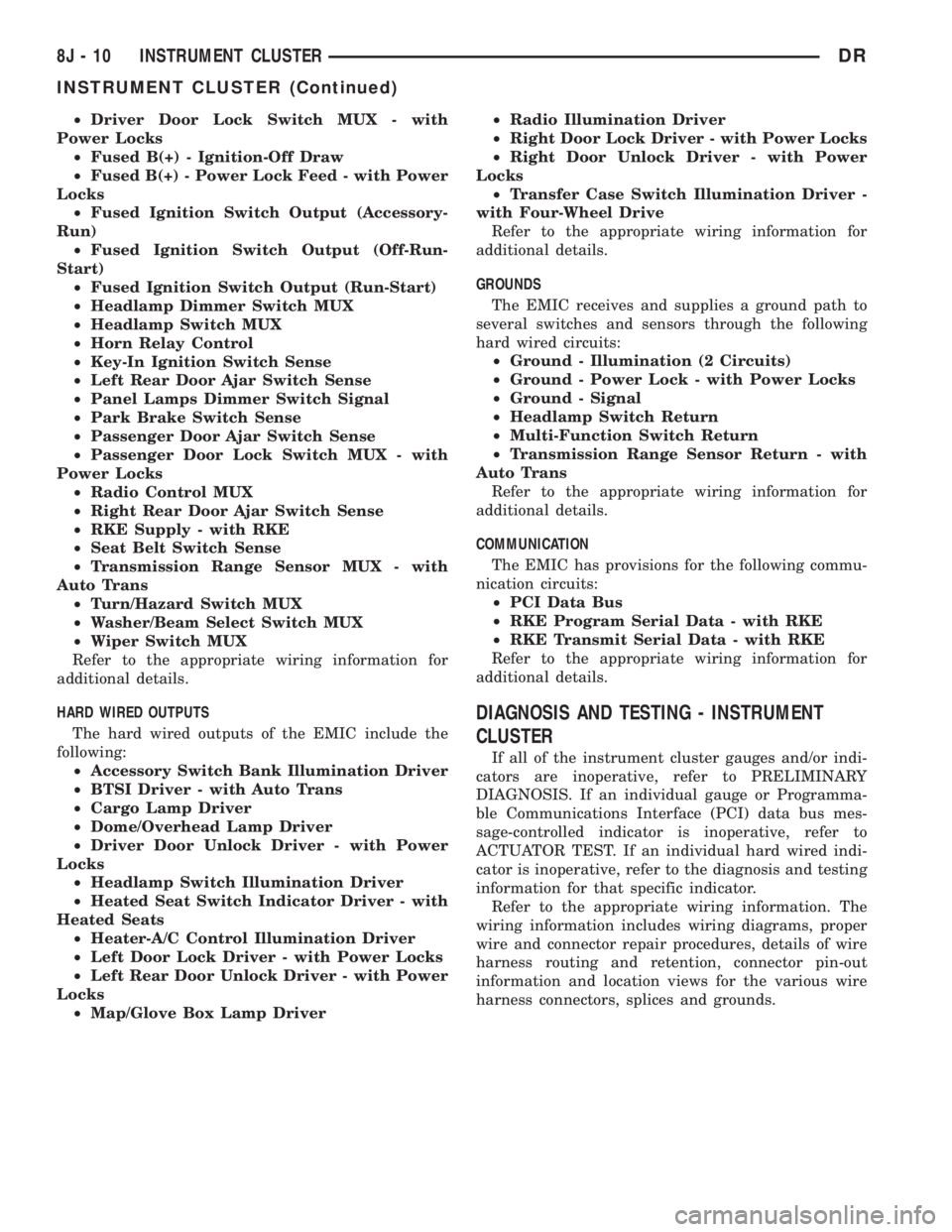
²Driver Door Lock Switch MUX - with
Power Locks
²Fused B(+) - Ignition-Off Draw
²Fused B(+) - Power Lock Feed - with Power
Locks
²Fused Ignition Switch Output (Accessory-
Run)
²Fused Ignition Switch Output (Off-Run-
Start)
²Fused Ignition Switch Output (Run-Start)
²Headlamp Dimmer Switch MUX
²Headlamp Switch MUX
²Horn Relay Control
²Key-In Ignition Switch Sense
²Left Rear Door Ajar Switch Sense
²Panel Lamps Dimmer Switch Signal
²Park Brake Switch Sense
²Passenger Door Ajar Switch Sense
²Passenger Door Lock Switch MUX - with
Power Locks
²Radio Control MUX
²Right Rear Door Ajar Switch Sense
²RKE Supply - with RKE
²Seat Belt Switch Sense
²Transmission Range Sensor MUX - with
Auto Trans
²Turn/Hazard Switch MUX
²Washer/Beam Select Switch MUX
²Wiper Switch MUX
Refer to the appropriate wiring information for
additional details.
HARD WIRED OUTPUTS
The hard wired outputs of the EMIC include the
following:
²Accessory Switch Bank Illumination Driver
²BTSI Driver - with Auto Trans
²Cargo Lamp Driver
²Dome/Overhead Lamp Driver
²Driver Door Unlock Driver - with Power
Locks
²Headlamp Switch Illumination Driver
²Heated Seat Switch Indicator Driver - with
Heated Seats
²Heater-A/C Control Illumination Driver
²Left Door Lock Driver - with Power Locks
²Left Rear Door Unlock Driver - with Power
Locks
²Map/Glove Box Lamp Driver²Radio Illumination Driver
²Right Door Lock Driver - with Power Locks
²Right Door Unlock Driver - with Power
Locks
²Transfer Case Switch Illumination Driver -
with Four-Wheel Drive
Refer to the appropriate wiring information for
additional details.
GROUNDS
The EMIC receives and supplies a ground path to
several switches and sensors through the following
hard wired circuits:
²Ground - Illumination (2 Circuits)
²Ground - Power Lock - with Power Locks
²Ground - Signal
²Headlamp Switch Return
²Multi-Function Switch Return
²Transmission Range Sensor Return - with
Auto Trans
Refer to the appropriate wiring information for
additional details.
COMMUNICATION
The EMIC has provisions for the following commu-
nication circuits:
²PCI Data Bus
²RKE Program Serial Data - with RKE
²RKE Transmit Serial Data - with RKE
Refer to the appropriate wiring information for
additional details.
DIAGNOSIS AND TESTING - INSTRUMENT
CLUSTER
If all of the instrument cluster gauges and/or indi-
cators are inoperative, refer to PRELIMINARY
DIAGNOSIS. If an individual gauge or Programma-
ble Communications Interface (PCI) data bus mes-
sage-controlled indicator is inoperative, refer to
ACTUATOR TEST. If an individual hard wired indi-
cator is inoperative, refer to the diagnosis and testing
information for that specific indicator.
Refer to the appropriate wiring information. The
wiring information includes wiring diagrams, proper
wire and connector repair procedures, details of wire
harness routing and retention, connector pin-out
information and location views for the various wire
harness connectors, splices and grounds.
8J - 10 INSTRUMENT CLUSTERDR
INSTRUMENT CLUSTER (Continued)
Page 506 of 2895
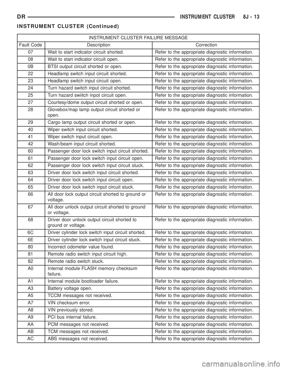
INSTRUMENT CLUSTER FAILURE MESSAGE
Fault Code Description Correction
07 Wait to start indicator circuit shorted. Refer to the appropriate diagnostic information.
08 Wait to start indicator circuit open. Refer to the appropriate diagnostic information.
0B BTSI output circuit shorted or open. Refer to the appropriate diagnostic information.
22 Headlamp switch input circuit shorted. Refer to the appropriate diagnostic information.
23 Headlamp switch input circuit open. Refer to the appropriate diagnostic information.
24 Turn hazard switch input circuit shorted. Refer to the appropriate diagnostic information.
25 Turn hazard swiitch inpot circuit open. Refer to the appropriate diagnostic information.
27 Courtesy/dome output circuit shorted or open. Refer to the appropriate diagnostic information.
28 Glovebox/map lamp output circuit shorted or
open.Refer to the appropriate diagnostic information.
29 Cargo lamp output circuit shorted or open. Refer to the appropriate diagnostic information.
40 Wiper switch input circuit shorted. Refer to the appropriate diagnostic information.
41 Wiper switch input circuit open. Refer to the appropriate diagnostic information.
42 Wash/beam input circuit shorted. Refer to the appropriate diagnostic information.
60 Passenger door lock switch input circuit shorted. Refer to the appropriate diagnostic information.
61 Passenger door lock switch input circuit open. Refer to the appropriate diagnostic information.
62 Passenger door lock switch input circuit stuck. Refer to the appropriate diagnostic information.
63 Driver door lock switch input circuit shorted. Refer to the appropriate diagnostic information.
64 Driver door lock switch input circuit open. Refer to the appropriate diagnostic information.
65 Driver door lock switch input circuit stuck. Refer to the appropriate diagnostic information.
66 All door lock output circuit shorted to ground or
voltage.Refer to the appropriate diagnostic information.
67 All door unlock output circuit shorted to ground
or voltage.Refer to the appropriate diagnostic information.
68 Driver door unlock output circuit shorted to
ground or voltage.Refer to the appropriate diagnostic information.
6C Driver cylinder lock switch input circuit shorted. Refer to the appropriate diagnostic information.
6E Driver cylinder lock switch input circuit stuck. Refer to the appropriate diagnostic information.
80 Incorrect odometer value found. Refer to the appropriate diagnostic information.
81 Remote radio switch input circuit high. Refer to the appropriate diagnostic information.
82 Remote radio switch stuck. Refer to the appropriate diagnostic information.
A0 Internal module FLASH memory checksum
failure.Refer to the appropriate diagnostic information.
A1 Internal module bootloader failure. Refer to the appropriate diagnostic information.
A3 Battery voltage open. Refer to the appropriate diagnostic information.
A5 TCCM messages not received. Refer to the appropriate diagnostic information.
A7 VIN checksum error. Refer to the appropriate diagnostic information.
A8 VIN previously stored. Refer to the appropriate diagnostic information.
A9 PCI bus internal failure. Refer to the appropriate diagnostic information.
AA PCM messages not received. Refer to the appropriate diagnostic information.
AB TCM messages not received. Refer to the appropriate diagnostic information.
AC ABS messages not received. Refer to the appropriate diagnostic information.
DRINSTRUMENT CLUSTER 8J - 13
INSTRUMENT CLUSTER (Continued)