fuel pressure DODGE RAM 2003 Service Repair Manual
[x] Cancel search | Manufacturer: DODGE, Model Year: 2003, Model line: RAM, Model: DODGE RAM 2003Pages: 2895, PDF Size: 83.15 MB
Page 19 of 2895
MAINTENANCE SCHEDULES
DESCRIPTION
Maintenance Schedule Information not included in
this section, is located in the appropriate Owner's
Manual.
There are two maintenance schedules that show
therequiredservice for your vehicle.
First is ScheduleªBº. It is for vehicles that are
operated under the conditions that are listed below
and at the beginning of the schedule.
²Day or night temperatures are below 0É C (32É
F).
²Stop and go driving.
²Extensive engine idling.
²Driving in dusty conditions.
²Short trips of less than 16 km (10 miles).
²More than 50% of your driving is at sustained
high speeds during hot weather, above 32É C (90É F).
²Trailer towing.
²Taxi, police, or delivery service (commercial ser-
vice).
²Off-road or desert operation.
²If equipped for and operating with E-85
(ethanol) fuel.
NOTE: Most vehicles are operated under the condi-
tions listed for Schedule(B(.
Second is ScheduleªAº. It is for vehicles that are
not operated under any of the conditions listed under
Schedule9B9.
Use the schedule that best describes your driving
conditions. Where time and mileage are listed, follow
the interval that occurs first.
CAUTION: Failure to perform the required mainte-
nance items may result in damage to the vehicle.
At Each Stop for Fuel
²Check the engine oil level about 5 minutes after
a fully warmed engine is shut off. Checking the oil
level while the vehicle is on level ground will
improve the accuracy of the oil level reading. Add oil
only when the level is at or below the ADD or MIN
mark.
²Check the windshield washer solvent and add if
required.
Once a Month
²Check tire pressure and look for unusual wear
or damage.
²Inspect the battery and clean and tighten the
terminals as required.
²Check the fluid levels of coolant reservoir, brake
master cylinder, power steering and transmission
and add as needed.
²Check all lights and all other electrical items for
correct operation.
At Each Oil Change
²Change the engine oil filter.
²Inspect the exhaust system.
²Inspect the brake hoses.
²Inspect the CV joints (if equipped) and front sus-
pension components.
²Check the automatic transmission fluid level.
²Check the manual transmission fluid level.
²Check the coolant level, hoses, and clamps.
²Rotate the tires at each oil change interval
shown on Schedule ªAº 10 000 km (6,000 miles) or
every other interval shown on Schedule ªBº 10 000
km (6,000 miles).
Schedule ªBº
Follow schedule ªBº if you usually operate your
vehicle under one or more of the following conditions.
²Day or night temperatures are below 0É C (32É
F).
²Stop and go driving.
²Extensive engine idling.
²Driving in dusty conditions.
²Short trips of less than 16 km (10 miles).
²More than 50% of your driving is at sustained
high speeds during hot weather, above 32É C (90É F).
²Trailer towing.
²Taxi, police, or delivery service (commercial ser-
vice).
²Off-road or desert operation.
²If equipped for and operating with E-85
(ethanol) fuel.
0 - 6 LUBRICATION & MAINTENANCEDR
Page 254 of 2895
CONDITION POSSIBLE CAUSES CORRECTION
Brakes Self Apply 1. Dump valve faulty. 1. Replace booster.
2. Contamination in hydraulic
system.2. Flush hydraulic system and replace
booster.
3. Restriction in booster return hose. 3. Replace hose.
Booster Chatter, Pedal
Vibration1. Slipping pump belt. 1. Replace power steering belt.
2. Low pump fluid level. 2. Fill pump and check for leaks.
Grabbing Brakes 1. Low pump flow. 1. Test and repair/replace pump.
2. Faulty spool valve action. 2. Replace booster.
STANDARD PROCEDURE - BLEEDING
The hydraulic booster is generally self-bleeding,
this procedure will normally bleed the air from the
booster. Normal driving and operation of the unit will
remove any remaining trapped air.
(1) Fill power steering pump reservoir.
(2) Disconnect fuel shutdown relay and crank the
engine for several seconds, Refer to Fuel System for
relay location and WARNING.
(3) Check fluid level and add if necessary.
(4) Connect fuel shutdown relay and start the
engine.
(5) Turn the steering wheel slowly from lock to
lock twice.
(6) Stop the engine and discharge the accumulator
by depressing the brake pedal 5 times.
(7) Start the engine and turn the steering wheel
slowly from lock to lock twice.
(8) Turn off the engine and check fluid level and
add if necessary.
NOTE: If fluid foaming occurs, wait for foam to dis-
sipate and repeat steps 7 and 8.
REMOVAL
NOTE: If the booster is being replaced because the
power steering fluid is contaminated, flush the
power steering system before replacing the booster.
(1) With engine off depress the brake pedal 5
times to discharge the accumulator.
(2) Remove brake lines from master cylinder.
(3) Remove mounting nuts from the master cylin-
der.
(4) Remove the bracket from the hydraulic booster
lines and master cylinder mounting studs.
(5) Remove the master cylinder.
(6) Remove the return hose and the two pressure
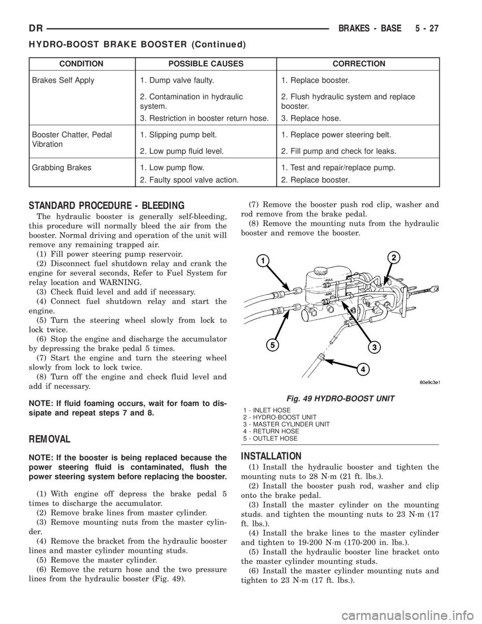
lines from the hydraulic booster (Fig. 49).(7) Remove the booster push rod clip, washer and
rod remove from the brake pedal.
(8) Remove the mounting nuts from the hydraulic
booster and remove the booster.INSTALLATION
(1) Install the hydraulic booster and tighten the
mounting nuts to 28 N´m (21 ft. lbs.).
(2) Install the booster push rod, washer and clip
onto the brake pedal.
(3) Install the master cylinder on the mounting
studs. and tighten the mounting nuts to 23 N´m (17
ft. lbs.).
(4) Install the brake lines to the master cylinder
and tighten to 19-200 N´m (170-200 in. lbs.).
(5) Install the hydraulic booster line bracket onto
the master cylinder mounting studs.
(6) Install the master cylinder mounting nuts and
tighten to 23 N´m (17 ft. lbs.).
Fig. 49 HYDRO-BOOST UNIT
1 - INLET HOSE
2 - HYDRO-BOOST UNIT
3 - MASTER CYLINDER UNIT
4 - RETURN HOSE
5 - OUTLET HOSE
DRBRAKES - BASE 5 - 27
HYDRO-BOOST BRAKE BOOSTER (Continued)
Page 385 of 2895
ENGINE CONTROL MODULE
DESCRIPTION - ECM
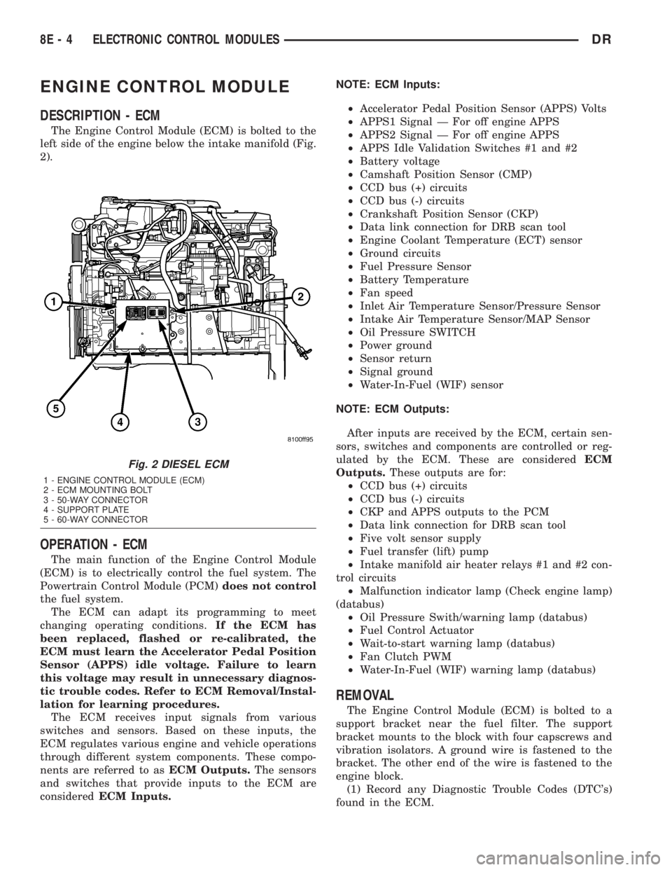
The Engine Control Module (ECM) is bolted to the
left side of the engine below the intake manifold (Fig.
2).
OPERATION - ECM
The main function of the Engine Control Module
(ECM) is to electrically control the fuel system. The
Powertrain Control Module (PCM)does not control
the fuel system.
The ECM can adapt its programming to meet
changing operating conditions.If the ECM has
been replaced, flashed or re-calibrated, the
ECM must learn the Accelerator Pedal Position
Sensor (APPS) idle voltage. Failure to learn
this voltage may result in unnecessary diagnos-
tic trouble codes. Refer to ECM Removal/Instal-
lation for learning procedures.
The ECM receives input signals from various
switches and sensors. Based on these inputs, the
ECM regulates various engine and vehicle operations
through different system components. These compo-
nents are referred to asECM Outputs.The sensors
and switches that provide inputs to the ECM are
consideredECM Inputs.NOTE: ECM Inputs:
²Accelerator Pedal Position Sensor (APPS) Volts
²APPS1 Signal Ð For off engine APPS
²APPS2 Signal Ð For off engine APPS
²APPS Idle Validation Switches #1 and #2
²Battery voltage
²Camshaft Position Sensor (CMP)
²CCD bus (+) circuits
²CCD bus (-) circuits
²Crankshaft Position Sensor (CKP)
²Data link connection for DRB scan tool
²Engine Coolant Temperature (ECT) sensor
²Ground circuits
²Fuel Pressure Sensor
²Battery Temperature
²Fan speed
²Inlet Air Temperature Sensor/Pressure Sensor
²Intake Air Temperature Sensor/MAP Sensor
²Oil Pressure SWITCH
²Power ground
²Sensor return
²Signal ground
²Water-In-Fuel (WIF) sensor
NOTE: ECM Outputs:
After inputs are received by the ECM, certain sen-
sors, switches and components are controlled or reg-
ulated by the ECM. These are consideredECM
Outputs.These outputs are for:
²CCD bus (+) circuits
²CCD bus (-) circuits
²CKP and APPS outputs to the PCM
²Data link connection for DRB scan tool
²Five volt sensor supply
²Fuel transfer (lift) pump
²Intake manifold air heater relays #1 and #2 con-
trol circuits
²Malfunction indicator lamp (Check engine lamp)
(databus)
²Oil Pressure Swith/warning lamp (databus)
²Fuel Control Actuator
²Wait-to-start warning lamp (databus)
²Fan Clutch PWM
²Water-In-Fuel (WIF) warning lamp (databus)
REMOVAL
The Engine Control Module (ECM) is bolted to a
support bracket near the fuel filter. The support
bracket mounts to the block with four capscrews and
vibration isolators. A ground wire is fastened to the
bracket. The other end of the wire is fastened to the
engine block.
(1) Record any Diagnostic Trouble Codes (DTC's)
found in the ECM.
Fig. 2 DIESEL ECM
1 - ENGINE CONTROL MODULE (ECM)
2 - ECM MOUNTING BOLT
3 - 50-WAY CONNECTOR
4 - SUPPORT PLATE
5 - 60-WAY CONNECTOR
8E - 4 ELECTRONIC CONTROL MODULESDR
Page 389 of 2895
POWERTRAIN CONTROL
MODULE
DESCRIPTION
DESCRIPTION - PCM
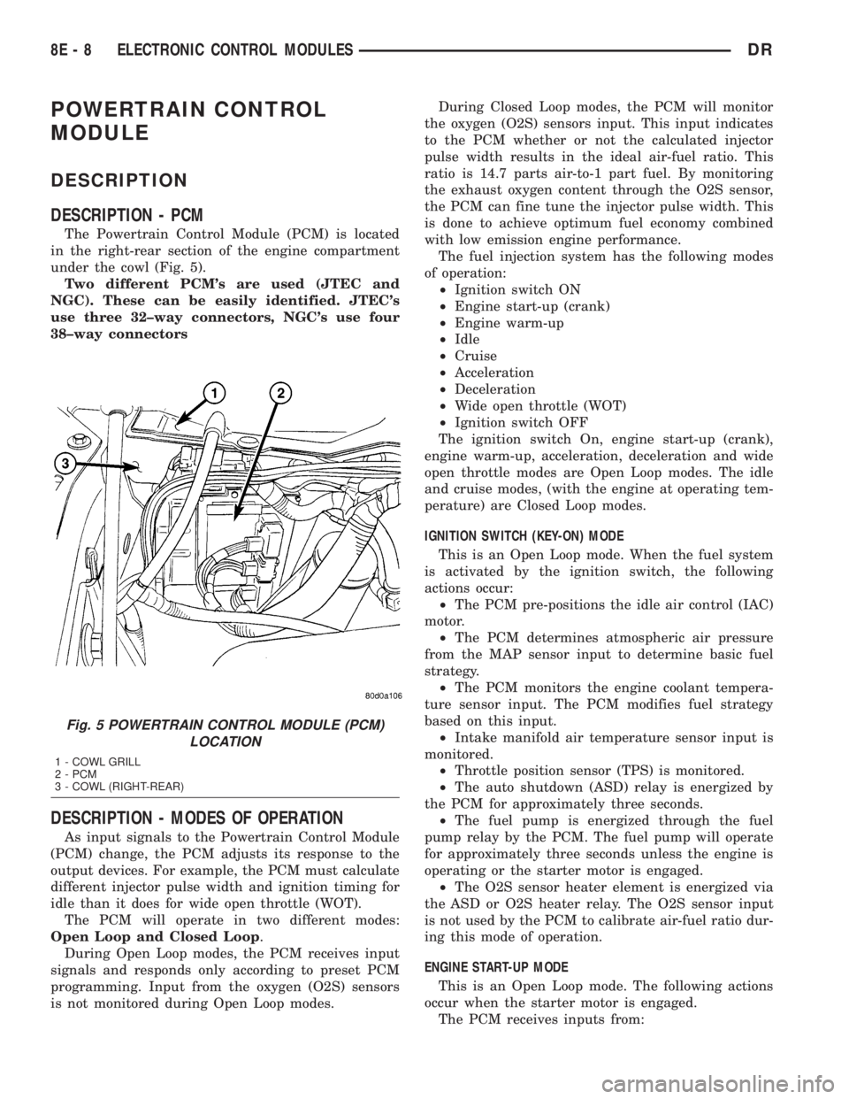
The Powertrain Control Module (PCM) is located
in the right-rear section of the engine compartment
under the cowl (Fig. 5).
Two different PCM's are used (JTEC and
NGC). These can be easily identified. JTEC's
use three 32±way connectors, NGC's use four
38±way connectors
DESCRIPTION - MODES OF OPERATION
As input signals to the Powertrain Control Module
(PCM) change, the PCM adjusts its response to the
output devices. For example, the PCM must calculate
different injector pulse width and ignition timing for
idle than it does for wide open throttle (WOT).
The PCM will operate in two different modes:
Open Loop and Closed Loop.
During Open Loop modes, the PCM receives input
signals and responds only according to preset PCM
programming. Input from the oxygen (O2S) sensors
is not monitored during Open Loop modes.During Closed Loop modes, the PCM will monitor
the oxygen (O2S) sensors input. This input indicates
to the PCM whether or not the calculated injector
pulse width results in the ideal air-fuel ratio. This
ratio is 14.7 parts air-to-1 part fuel. By monitoring
the exhaust oxygen content through the O2S sensor,
the PCM can fine tune the injector pulse width. This
is done to achieve optimum fuel economy combined
with low emission engine performance.
The fuel injection system has the following modes
of operation:
²Ignition switch ON
²Engine start-up (crank)
²Engine warm-up
²Idle
²Cruise
²Acceleration
²Deceleration
²Wide open throttle (WOT)
²Ignition switch OFF
The ignition switch On, engine start-up (crank),
engine warm-up, acceleration, deceleration and wide
open throttle modes are Open Loop modes. The idle
and cruise modes, (with the engine at operating tem-
perature) are Closed Loop modes.
IGNITION SWITCH (KEY-ON) MODE
This is an Open Loop mode. When the fuel system
is activated by the ignition switch, the following
actions occur:
²The PCM pre-positions the idle air control (IAC)
motor.
²The PCM determines atmospheric air pressure
from the MAP sensor input to determine basic fuel
strategy.
²The PCM monitors the engine coolant tempera-
ture sensor input. The PCM modifies fuel strategy
based on this input.
²Intake manifold air temperature sensor input is
monitored.
²Throttle position sensor (TPS) is monitored.
²The auto shutdown (ASD) relay is energized by
the PCM for approximately three seconds.
²The fuel pump is energized through the fuel
pump relay by the PCM. The fuel pump will operate
for approximately three seconds unless the engine is
operating or the starter motor is engaged.
²The O2S sensor heater element is energized via
the ASD or O2S heater relay. The O2S sensor input
is not used by the PCM to calibrate air-fuel ratio dur-
ing this mode of operation.
ENGINE START-UP MODE
This is an Open Loop mode. The following actions
occur when the starter motor is engaged.
The PCM receives inputs from:
Fig. 5 POWERTRAIN CONTROL MODULE (PCM)
LOCATION
1 - COWL GRILL
2 - PCM
3 - COWL (RIGHT-REAR)
8E - 8 ELECTRONIC CONTROL MODULESDR
Page 390 of 2895
²Battery voltage
²Engine coolant temperature sensor
²Crankshaft position sensor
²Intake manifold air temperature sensor
²Manifold absolute pressure (MAP) sensor
²Throttle position sensor (TPS)
²Camshaft position sensor signal
The PCM monitors the crankshaft position sensor.
If the PCM does not receive a crankshaft position
sensor signal within 3 seconds of cranking the
engine, it will shut down the fuel injection system.
The fuel pump is activated by the PCM through
the fuel pump relay.
Voltage is applied to the fuel injectors with the
ASD relay via the PCM. The PCM will then control
the injection sequence and injector pulse width by
turning the ground circuit to each individual injector
on and off.
The PCM determines the proper ignition timing
according to input received from the crankshaft posi-
tion sensor.
ENGINE WARM-UP MODE
This is an Open Loop mode. During engine warm-
up, the PCM receives inputs from:
²Battery voltage
²Crankshaft position sensor
²Engine coolant temperature sensor
²Intake manifold air temperature sensor
²Manifold absolute pressure (MAP) sensor
²Throttle position sensor (TPS)
²Camshaft position sensor signal
²Park/neutral switch (gear indicator signalÐauto.
trans. only)
²Air conditioning select signal (if equipped)
²Air conditioning request signal (if equipped)
Based on these inputs the following occurs:
²Voltage is applied to the fuel injectors with the
ASD relay via the PCM. The PCM will then control
the injection sequence and injector pulse width by
turning the ground circuit to each individual injector
on and off.
²The PCM adjusts engine idle speed through the
idle air control (IAC) motor and adjusts ignition tim-
ing.
²The PCM operates the A/C compressor clutch
through the A/C compressor clutch relay. This is done
if A/C has been selected by the vehicle operator and
specified pressures are met at the high and low±pres-
sure A/C switches. Refer to Heating and Air Condi-
tioning for additional information.
²When engine has reached operating tempera-
ture, the PCM will begin monitoring O2S sensor
input. The system will then leave the warm-up mode
and go into closed loop operation.IDLE MODE
When the engine is at operating temperature, this
is a Closed Loop mode. At idle speed, the PCM
receives inputs from:
²Air conditioning select signal (if equipped)
²Air conditioning request signal (if equipped)
²Battery voltage
²Crankshaft position sensor
²Engine coolant temperature sensor
²Intake manifold air temperature sensor
²Manifold absolute pressure (MAP) sensor
²Throttle position sensor (TPS)
²Camshaft position sensor signal
²Battery voltage
²Park/neutral switch (gear indicator signalÐauto.
trans. only)
²Oxygen sensors
Based on these inputs, the following occurs:
²Voltage is applied to the fuel injectors with the
ASD relay via the PCM. The PCM will then control
injection sequence and injector pulse width by turn-
ing the ground circuit to each individual injector on
and off.
²The PCM monitors the O2S sensor input and
adjusts air-fuel ratio by varying injector pulse width.
It also adjusts engine idle speed through the idle air
control (IAC) motor.
²The PCM adjusts ignition timing by increasing
and decreasing spark advance.
²The PCM operates the A/C compressor clutch
through the A/C compressor clutch relay. This is done
if A/C has been selected by the vehicle operator and
specified pressures are met at the high and low±pres-
sure A/C switches. Refer to Heating and Air Condi-
tioning for additional information.
CRUISE MODE
When the engine is at operating temperature, this
is a Closed Loop mode. At cruising speed, the PCM
receives inputs from:
²Air conditioning select signal (if equipped)
²Air conditioning request signal (if equipped)
²Battery voltage
²Engine coolant temperature sensor
²Crankshaft position sensor
²Intake manifold air temperature sensor
²Manifold absolute pressure (MAP) sensor
²Throttle position sensor (TPS)
²Camshaft position sensor signal
²Park/neutral switch (gear indicator signalÐauto.
trans. only)
²Oxygen (O2S) sensors
Based on these inputs, the following occurs:
²Voltage is applied to the fuel injectors with the
ASD relay via the PCM. The PCM will then adjust
DRELECTRONIC CONTROL MODULES 8E - 9
POWERTRAIN CONTROL MODULE (Continued)
Page 391 of 2895
the injector pulse width by turning the ground circuit
to each individual injector on and off.
²The PCM monitors the O2S sensor input and
adjusts air-fuel ratio. It also adjusts engine idle
speed through the idle air control (IAC) motor.
²The PCM adjusts ignition timing by turning the
ground path to the coil(s) on and off.
²The PCM operates the A/C compressor clutch
through the clutch relay. This happens if A/C has
been selected by the vehicle operator and requested
by the A/C thermostat.
ACCELERATION MODE
This is an Open Loop mode. The PCM recognizes
an abrupt increase in throttle position or MAP pres-
sure as a demand for increased engine output and
vehicle acceleration. The PCM increases injector
pulse width in response to increased throttle opening.
DECELERATION MODE
When the engine is at operating temperature, this
is an Open Loop mode. During hard deceleration, the
PCM receives the following inputs.
²Air conditioning select signal (if equipped)
²Air conditioning request signal (if equipped)
²Battery voltage
²Engine coolant temperature sensor
²Crankshaft position sensor
²Intake manifold air temperature sensor
²Manifold absolute pressure (MAP) sensor
²Throttle position sensor (TPS)
²Camshaft position sensor signal
²Park/neutral switch (gear indicator signalÐauto.
trans. only)
²Vehicle speed
If the vehicle is under hard deceleration with the
proper rpm and closed throttle conditions, the PCM
will ignore the oxygen sensor input signal. The PCM
will enter a fuel cut-off strategy in which it will not
supply a ground to the injectors. If a hard decelera-
tion does not exist, the PCM will determine the
proper injector pulse width and continue injection.
Based on the above inputs, the PCM will adjust
engine idle speed through the idle air control (IAC)
motor.
The PCM adjusts ignition timing by turning the
ground path to the coil on and off.
WIDE OPEN THROTTLE MODE
This is an Open Loop mode. During wide open
throttle operation, the PCM receives the following
inputs.
²Battery voltage
²Crankshaft position sensor
²Engine coolant temperature sensor
²Intake manifold air temperature sensor
²Manifold absolute pressure (MAP) sensor²Throttle position sensor (TPS)
²Camshaft position sensor signal
During wide open throttle conditions, the following
occurs:
²Voltage is applied to the fuel injectors with the
ASD relay via the PCM. The PCM will then control
the injection sequence and injector pulse width by
turning the ground circuit to each individual injector
on and off. The PCM ignores the oxygen sensor input
signal and provides a predetermined amount of addi-
tional fuel. This is done by adjusting injector pulse
width.
²The PCM adjusts ignition timing by turning the
ground path to the coil(s) on and off.
IGNITION SWITCH OFF MODE
When ignition switch is turned to OFF position,
the PCM stops operating the injectors, ignition coil,
ASD relay and fuel pump relay.
DESCRIPTION - 5 VOLT SUPPLIES
Two different Powertrain Control Module (PCM)
five volt supply circuits are used; primary and sec-
ondary.
DESCRIPTION - IGNITION CIRCUIT SENSE
This circuit ties the ignition switch to the Power-
train Control Module (PCM).
DESCRIPTION - POWER GROUNDS
The Powertrain Control Module (PCM) has 2 main
grounds. Both of these grounds are referred to as
power grounds. All of the high-current, noisy, electri-
cal devices are connected to these grounds as well as
all of the sensor returns. The sensor return comes
into the sensor return circuit, passes through noise
suppression, and is then connected to the power
ground.
The power ground is used to control ground cir-
cuits for the following PCM loads:
²Generator field winding
²Fuel injectors
²Ignition coil(s)
²Certain relays/solenoids
²Certain sensors
DESCRIPTION - SENSOR RETURN
The Sensor Return circuits are internal to the Pow-
ertrain Control Module (PCM).
Sensor Return provides a low±noise ground refer-
ence for all engine control system sensors. Refer to
Power Grounds for more information.
8E - 10 ELECTRONIC CONTROL MODULESDR
POWERTRAIN CONTROL MODULE (Continued)
Page 392 of 2895
OPERATION
OPERATION - PCM
The PCM operates the fuel system. The PCM is a
pre-programmed, triple microprocessor digital com-
puter. It regulates ignition timing, air-fuel ratio,
emission control devices, charging system, certain
transmission features, speed control, air conditioning
compressor clutch engagement and idle speed. The
PCM can adapt its programming to meet changing
operating conditions.
The PCM receives input signals from various
switches and sensors. Based on these inputs, the
PCM regulates various engine and vehicle operations
through different system components. These compo-
nents are referred to as Powertrain Control Module
(PCM) Outputs. The sensors and switches that pro-
vide inputs to the PCM are considered Powertrain
Control Module (PCM) Inputs.
The PCM adjusts ignition timing based upon
inputs it receives from sensors that react to: engine
rpm, manifold absolute pressure, engine coolant tem-
perature, throttle position, transmission gear selec-
tion (automatic transmission), vehicle speed, power
steering pump pressure, and the brake switch.
The PCM adjusts idle speed based on inputs it
receives from sensors that react to: throttle position,
vehicle speed, transmission gear selection, engine
coolant temperature and from inputs it receives from
the air conditioning clutch switch and brake switch.
Based on inputs that it receives, the PCM adjusts
ignition coil dwell. The PCM also adjusts the gener-
ator charge rate through control of the generator
field and provides speed control operation.
NOTE: PCM Inputs:
²ABS module (if equipped)
²A/C request (if equipped with factory A/C)
²A/C select (if equipped with factory A/C)
²A/C pressure transducer
²Auto shutdown (ASD) sense
²Battery temperature sensor
²Battery voltage
²Brake switch
²J1850 bus (+) circuits
²J1850 bus (-) circuits
²Camshaft position sensor signal
²Crankshaft position sensor
²Data link connection for DRB scan tool
²EATX module (if equipped)
²Engine coolant temperature sensor
²Fuel level (through J1850 circuitry)
²Generator (battery voltage) output
²Ignition circuit sense (ignition switch in on/off/
crank/run position)²Intake manifold air temperature sensor
²Knock sensors (2 on 3.7L engine)
²Leak detection pump (switch) sense (if equipped)
²Manifold absolute pressure (MAP) sensor
²Oil pressure
²Oxygen sensors
²Park/neutral switch (auto. trans. only)
²Power ground
²Power steering pressure switch (if equipped)
²Sensor return
²Signal ground
²Speed control multiplexed single wire input
²Throttle position sensor
²Transfer case switch (4WD range position)
²Vehicle speed signal
NOTE: PCM Outputs:
²A/C clutch relay
²Auto shutdown (ASD) relay
²J1850 bus (+/-) circuits for: speedometer, voltme-
ter, fuel gauge, oil pressure gauge/lamp, engine temp.
gauge and speed control warn. lamp
²Data link connection for DRB scan tool
²EGR valve control solenoid (if equipped)
²EVAP canister purge solenoid
²Five volt sensor supply (primary)
²Five volt sensor supply (secondary)
²Fuel injectors
²Fuel pump relay
²Generator field driver (-)
²Generator field driver (+)
²Idle air control (IAC) motor
²Ignition coil(s)
²Leak detection pump (if equipped)
²Malfunction indicator lamp (Check engine lamp).
Driven through J1850 circuits.
²Oxygen sensor heater relays
²Oxygen sensors (pulse width modulated)
²Radiator cooling fan relay (pulse width modu-
lated)
²Speed control vacuum solenoid
²Speed control vent solenoid
²Tachometer (if equipped). Driven through J1850
circuits.
²Transmission convertor clutch circuit. Driven
through J1850 circuits.
OPERATION - 5 VOLT SUPPLIES
Primary 5±volt supply:
²supplies the required 5 volt power source to the
Crankshaft Position (CKP) sensor.
²supplies the required 5 volt power source to the
Camshaft Position (CMP) sensor.
²supplies a reference voltage for the Manifold
Absolute Pressure (MAP) sensor.
DRELECTRONIC CONTROL MODULES 8E - 11
POWERTRAIN CONTROL MODULE (Continued)
Page 393 of 2895
²supplies a reference voltage for the Throttle
Position Sensor (TPS) sensor.
Secondary 5±volt supply:
²supplies the required 5 volt power source to the
oil pressure sensor.
²supplies the required 5 volt power source for the
Vehicle Speed Sensor (VSS) (if equipped).
²supplies the 5 volt power source to the transmis-
sion pressure sensor (certain automatic transmis-
sions).
OPERATION - IGNITION CIRCUIT SENSE
The ignition circuit sense input tells the PCM the
ignition switch has energized the ignition circuit.
Battery voltage is also supplied to the PCM
through the ignition switch when the ignition is in
the RUN or START position. This is referred to as
the9ignition sense9circuit and is used to9wake up9
the PCM. Voltage on the ignition input can be as low
as 6 volts and the PCM will still function. Voltage is
supplied to this circuit to power the PCM's 8-volt reg-
ulator and to allow the PCM to perform fuel, ignition
and emissions control functions.
REMOVAL
USE THE DRB SCAN TOOL TO REPROGRAM
THE NEW POWERTRAIN CONTROL MODULE
(PCM) WITH THE VEHICLES ORIGINAL IDEN-
TIFICATION NUMBER (VIN) AND THE VEHI-
CLES ORIGINAL MILEAGE. IF THIS STEP IS
NOT DONE, A DIAGNOSTIC TROUBLE CODE
(DTC) MAY BE SET.
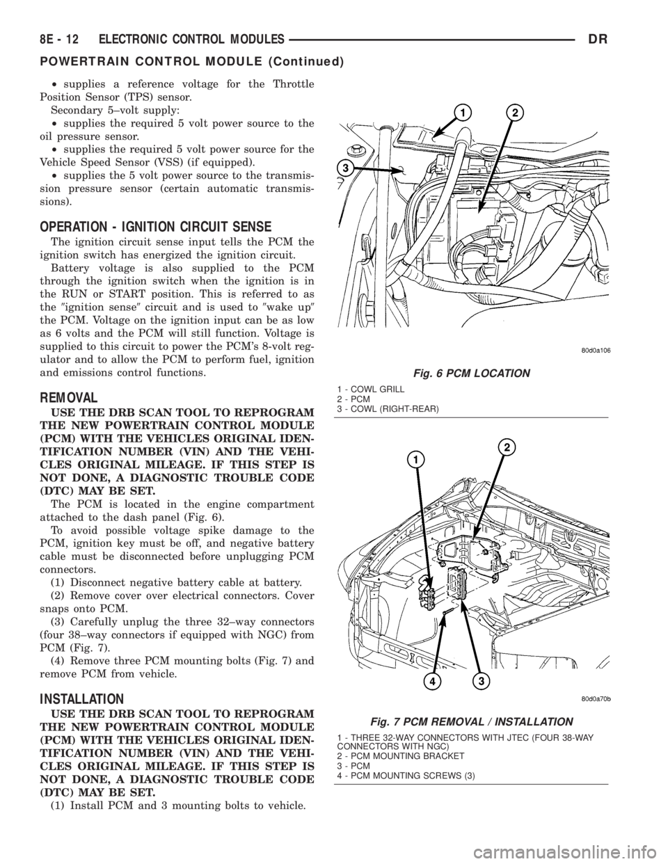
The PCM is located in the engine compartment
attached to the dash panel (Fig. 6).
To avoid possible voltage spike damage to the
PCM, ignition key must be off, and negative battery
cable must be disconnected before unplugging PCM
connectors.
(1) Disconnect negative battery cable at battery.
(2) Remove cover over electrical connectors. Cover
snaps onto PCM.
(3) Carefully unplug the three 32±way connectors
(four 38±way connectors if equipped with NGC) from
PCM (Fig. 7).
(4) Remove three PCM mounting bolts (Fig. 7) and
remove PCM from vehicle.
INSTALLATION
USE THE DRB SCAN TOOL TO REPROGRAM
THE NEW POWERTRAIN CONTROL MODULE
(PCM) WITH THE VEHICLES ORIGINAL IDEN-
TIFICATION NUMBER (VIN) AND THE VEHI-
CLES ORIGINAL MILEAGE. IF THIS STEP IS
NOT DONE, A DIAGNOSTIC TROUBLE CODE
(DTC) MAY BE SET.
(1) Install PCM and 3 mounting bolts to vehicle.
Fig. 6 PCM LOCATION
1 - COWL GRILL
2 - PCM
3 - COWL (RIGHT-REAR)
Fig. 7 PCM REMOVAL / INSTALLATION
1 - THREE 32-WAY CONNECTORS WITH JTEC (FOUR 38-WAY
CONNECTORS WITH NGC)
2 - PCM MOUNTING BRACKET
3 - PCM
4 - PCM MOUNTING SCREWS (3)
8E - 12 ELECTRONIC CONTROL MODULESDR
POWERTRAIN CONTROL MODULE (Continued)
Page 494 of 2895
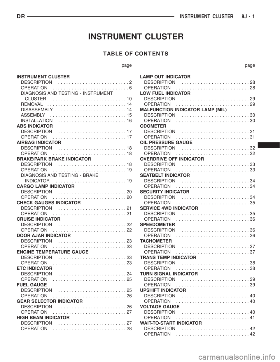
INSTRUMENT CLUSTER
TABLE OF CONTENTS
page page
INSTRUMENT CLUSTER
DESCRIPTION..........................2
OPERATION............................6
DIAGNOSIS AND TESTING - INSTRUMENT
CLUSTER...........................10
REMOVAL.............................14
DISASSEMBLY.........................14
ASSEMBLY............................15
INSTALLATION.........................16
ABS INDICATOR
DESCRIPTION.........................17
OPERATION...........................17
AIRBAG INDICATOR
DESCRIPTION.........................18
OPERATION...........................18
BRAKE/PARK BRAKE INDICATOR
DESCRIPTION.........................18
OPERATION...........................19
DIAGNOSIS AND TESTING - BRAKE
INDICATOR..........................19
CARGO LAMP INDICATOR
DESCRIPTION.........................20
OPERATION...........................20
CHECK GAUGES INDICATOR
DESCRIPTION.........................21
OPERATION...........................21
CRUISE INDICATOR
DESCRIPTION.........................22
OPERATION...........................22
DOOR AJAR INDICATOR
DESCRIPTION.........................23
OPERATION...........................23
ENGINE TEMPERATURE GAUGE
DESCRIPTION.........................23
OPERATION...........................23
ETC INDICATOR
DESCRIPTION.........................24
OPERATION...........................25
FUEL GAUGE
DESCRIPTION.........................25
OPERATION...........................26
GEAR SELECTOR INDICATOR
DESCRIPTION.........................26
OPERATION...........................27
HIGH BEAM INDICATOR
DESCRIPTION.........................27
OPERATION...........................28LAMP OUT INDICATOR
DESCRIPTION.........................28
OPERATION...........................28
LOW FUEL INDICATOR
DESCRIPTION.........................29
OPERATION...........................29
MALFUNCTION INDICATOR LAMP (MIL)
DESCRIPTION.........................30
OPERATION...........................30
ODOMETER
DESCRIPTION.........................31
OPERATION...........................31
OIL PRESSURE GAUGE
DESCRIPTION.........................32
OPERATION...........................32
OVERDRIVE OFF INDICATOR
DESCRIPTION.........................33
OPERATION...........................33
SEATBELT INDICATOR
DESCRIPTION.........................34
OPERATION...........................34
SECURITY INDICATOR
DESCRIPTION.........................34
OPERATION...........................35
SERVICE 4WD INDICATOR
DESCRIPTION.........................35
OPERATION...........................36
SPEEDOMETER
DESCRIPTION.........................36
OPERATION...........................36
TACHOMETER
DESCRIPTION.........................37
OPERATION...........................37
TRANS TEMP INDICATOR
DESCRIPTION.........................38
OPERATION...........................38
TURN SIGNAL INDICATOR
DESCRIPTION.........................39
OPERATION...........................39
UPSHIFT INDICATOR
DESCRIPTION.........................40
OPERATION...........................40
VOLTAGE GAUGE
DESCRIPTION.........................40
OPERATION...........................41
WAIT-TO-START INDICATOR
DESCRIPTION.........................42
OPERATION...........................42
DRINSTRUMENT CLUSTER 8J - 1
Page 498 of 2895
the vehicle speed remains greater than about twenty-
four kilometers-per-hour (fifteen miles-per-hour).
²Vacuum Fluorescent Display Synchroniza-
tion- The EMIC transmits electronic panel lamp
dimming level messages which allows all other elec-
tronic modules on the PCI data bus with Vacuum
Fluorescent Display (VFD) units to coordinate their
illumination intensity with that of the EMIC VFD
units.
²Vehicle Theft Security System- The EMIC
monitors inputs from the door cylinder lock switch-
(es), the door ajar switches, the ignition switch, and
the Remote Keyless Entry (RKE) receiver module,
then provides electronic horn and lighting request
messages to the Front Control Module (FCM) located
on the Integrated Power Module (IPM) for the appro-
priate VTSS alarm output features.
²Wiper/Washer System Control- The EMIC
provides electronic wiper and/or washer request mes-
sages to the Front Control Module (FCM) located on
the Integrated Power Module (IPM) for the appropri-
ate wiper and washer system features. (Refer to 8 -
ELECTRICAL/WIPERS/WASHERS - DESCRIP-
TION).
The EMIC houses six analog gauges and has pro-
visions for up to twenty-three indicators (Fig. 3) or
(Fig. 4). The EMIC includes the following analog
gauges:
²Coolant Temperature Gauge
²Fuel Gauge
²Oil Pressure Gauge
²Speedometer
²Tachometer
²Voltage Gauge
Some of the EMIC indicators are automatically
configured when the EMIC is connected to the vehi-
cle electrical system for compatibility with certain
optional equipment or equipment required for regula-
tory purposes in certain markets. While each EMIC
may have provisions for indicators to support every
available option, the configurable indicators will not
be functional in a vehicle that does not have the
equipment that an indicator supports. The EMIC
includes provisions for the following indicators (Fig.
3) or (Fig. 4):
²Airbag Indicator (with Airbag System only)
²Antilock Brake System (ABS) Indicator
(with ABS or Rear Wheel Anti-Lock [RWAL]
brakes only)
²Brake Indicator
²Cargo Lamp Indicator
²Check Gauges Indicator
²Cruise Indicator (with Speed Control only)
²Door Ajar Indicator
²Electronic Throttle Control (ETC) Indicator
(with 5.7L Gasoline Engine only)²Gear Selector Indicator (with Automatic
Transmission only)
²High Beam Indicator
²Lamp Out Indicator
²Low Fuel Indicator
²Malfunction Indicator Lamp (MIL)
²Overdrive-Off Indicator (with Automatic
Transmission only)
²Seatbelt Indicator
²Security Indicator (with Sentry Key Immo-
bilizer & Vehicle Theft Security Systems only)
²Service Four-Wheel Drive Indicator (with
Four-Wheel Drive only)
²Transmission Overtemp Indicator (with
Automatic Transmission only)
²Turn Signal (Right and Left) Indicators
²Upshift Indicator (with Manual Transmis-
sion only)
²Washer Fluid Indicator
²Wait-To-Start Indicator (with Diesel Engine
only)
²Water-In-Fuel Indicator (with Diesel Engine
only)
Each indicator in the EMIC, except those located
within one of the VFD units, is illuminated by a ded-
icated LED that is soldered onto the EMIC electronic
circuit board. The LED units are not available for
service replacement and, if damaged or faulty, the
entire EMIC must be replaced. Cluster illumination
is accomplished by dimmable incandescent back
lighting, which illuminates the gauges for visibility
when the exterior lighting is turned on. Each of the
incandescent bulbs is secured by an integral bulb
holder to the electronic circuit board from the back of
the cluster housing.
Hard wired circuitry connects the EMIC to the
electrical system of the vehicle. These hard wired cir-
cuits are integral to several wire harnesses, which
are routed throughout the vehicle and retained by
many different methods. These circuits may be con-
nected to each other, to the vehicle electrical system
and to the EMIC through the use of a combination of
soldered splices, splice block connectors, and many
different types of wire harness terminal connectors
and insulators. Refer to the appropriate wiring infor-
mation. The wiring information includes wiring dia-
grams, proper wire and connector repair procedures,
further details on wire harness routing and reten-
tion, as well as pin-out and location views for the
various wire harness connectors, splices and grounds.
The EMIC modules for this model are serviced only
as complete units. The EMIC module cannot be
adjusted or repaired. If a gauge, an LED indicator, a
VFD unit, the electronic circuit board, the circuit
board hardware, the cluster overlay, or the EMIC
housing are damaged or faulty, the entire EMIC mod-
DRINSTRUMENT CLUSTER 8J - 5
INSTRUMENT CLUSTER (Continued)