instrument cluster DODGE RAM 2003 Service Repair Manual
[x] Cancel search | Manufacturer: DODGE, Model Year: 2003, Model line: RAM, Model: DODGE RAM 2003Pages: 2895, PDF Size: 83.15 MB
Page 1 of 2895
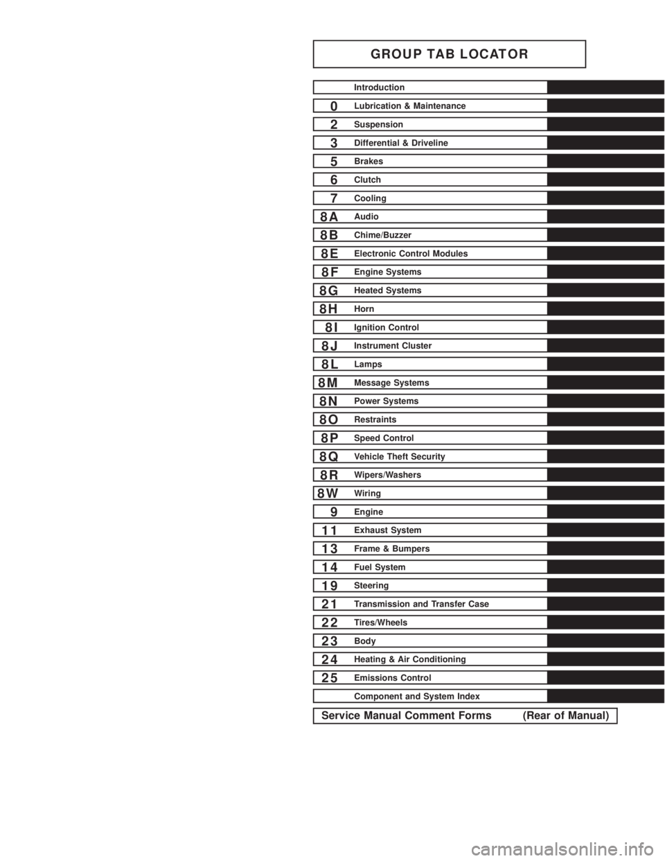
GROUP TAB LOCATOR
Introduction
0Lubrication & Maintenance
2Suspension
3Differential & Driveline
5Brakes
6Clutch
7Cooling
8AAudio
8BChime/Buzzer
8EElectronic Control Modules
8FEngine Systems
8GHeated Systems
8HHorn
8IIgnition Control
8JInstrument Cluster
8LLamps
8MMessage Systems
8NPower Systems
8ORestraints
8PSpeed Control
8QVehicle Theft Security
8RWipers/Washers
8WWiring
9Engine
11Exhaust System
13Frame & Bumpers
14Fuel System
19Steering
21Transmission and Transfer Case
22Tires/Wheels
23Body
24Heating & Air Conditioning
25Emissions Control
Component and System Index
Service Manual Comment Forms (Rear of Manual)
Page 294 of 2895
WARNING: DO NOT REMOVE CYLINDER BLOCK
DRAIN PLUGS OR LOOSEN RADIATOR DRAIN-
COCK WITH SYSTEM HOT AND UNDER PRESSURE.
SERIOUS BURNS FROM COOLANT CAN OCCUR.
Drain sufficient coolant to allow thermostat
removal. (Refer to 7 - COOLING/ENGINE/ENGINE
COOLANT THERMOSTAT - REMOVAL). Remove
accessory drive belt (Refer to 7 - COOLING/ACCES-
SORY DRIVE/DRIVE BELTS - REMOVAL).
Add coolant to radiator to bring level to within 6.3
mm (1/4 in) of the top of the thermostat housing.CAUTION: Avoid overheating. Do not operate
engine for an excessive period of time. Open drain-
cock immediately after test to eliminate boil over.
Start engine and accelerate rapidly three times, to
approximately 3000 rpm while observing coolant. If
internal engine combustion gases are leaking into
cooling system, bubbles will appear in coolant. If bub-
bles do not appear, internal combustion gas leakage
is not present.
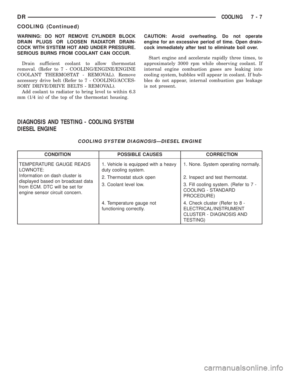
DIAGNOSIS AND TESTING - COOLING SYSTEM
DIESEL ENGINE
COOLING SYSTEM DIAGNOSISÐDIESEL ENGINE
CONDITION POSSIBLE CAUSES CORRECTION
TEMPERATURE GAUGE READS
LOWNOTE:
Information on dash cluster is
displayed based on broadcast data
from ECM. DTC will be set for
engine sensor circuit concern.1. Vehicle is equipped with a heavy
duty cooling system.1. None. System operating normally.
2. Thermostat stuck open 2. Inspect and test thermostat.
3. Coolant level low. 3. Fill cooling system. (Refer to 7 -
COOLING - STANDARD
PROCEDURE)
4. Temperature gauge not
functioning correctly.4. Check cluster (Refer to 8 -
ELECTRICAL/INSTRUMENT
CLUSTER - DIAGNOSIS AND
TESTING)
DRCOOLING 7 - 7
COOLING (Continued)
Page 295 of 2895
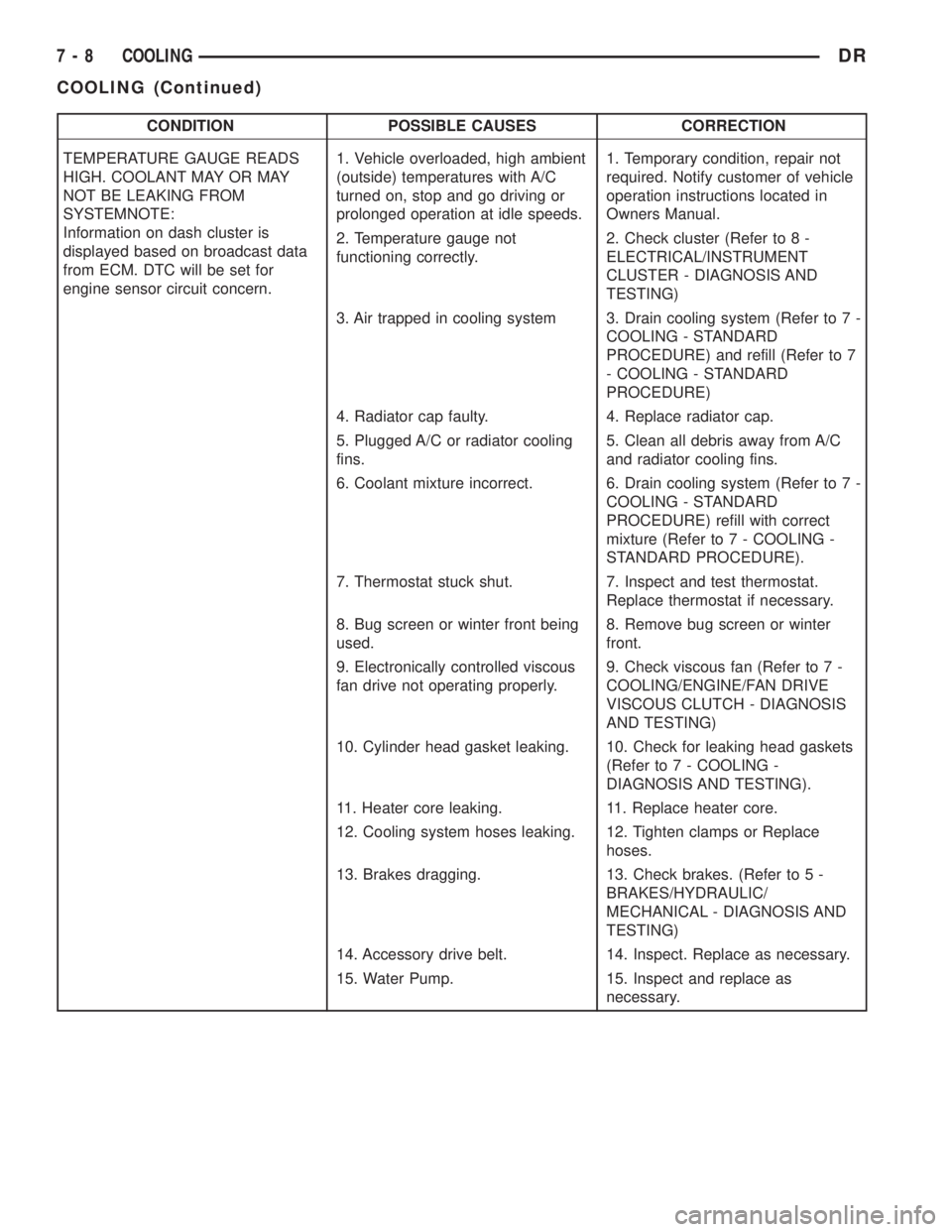
CONDITION POSSIBLE CAUSES CORRECTION
TEMPERATURE GAUGE READS
HIGH. COOLANT MAY OR MAY
NOT BE LEAKING FROM
SYSTEMNOTE:
Information on dash cluster is
displayed based on broadcast data
from ECM. DTC will be set for
engine sensor circuit concern.1. Vehicle overloaded, high ambient
(outside) temperatures with A/C
turned on, stop and go driving or
prolonged operation at idle speeds.1. Temporary condition, repair not
required. Notify customer of vehicle
operation instructions located in
Owners Manual.
2. Temperature gauge not
functioning correctly.2. Check cluster (Refer to 8 -
ELECTRICAL/INSTRUMENT
CLUSTER - DIAGNOSIS AND
TESTING)
3. Air trapped in cooling system 3. Drain cooling system (Refer to 7 -
COOLING - STANDARD
PROCEDURE) and refill (Refer to 7
- COOLING - STANDARD
PROCEDURE)
4. Radiator cap faulty. 4. Replace radiator cap.
5. Plugged A/C or radiator cooling
fins.5. Clean all debris away from A/C
and radiator cooling fins.
6. Coolant mixture incorrect. 6. Drain cooling system (Refer to 7 -
COOLING - STANDARD
PROCEDURE) refill with correct
mixture (Refer to 7 - COOLING -
STANDARD PROCEDURE).
7. Thermostat stuck shut. 7. Inspect and test thermostat.
Replace thermostat if necessary.
8. Bug screen or winter front being
used.8. Remove bug screen or winter
front.
9. Electronically controlled viscous
fan drive not operating properly.9. Check viscous fan (Refer to 7 -
COOLING/ENGINE/FAN DRIVE
VISCOUS CLUTCH - DIAGNOSIS
AND TESTING)
10. Cylinder head gasket leaking. 10. Check for leaking head gaskets
(Refer to 7 - COOLING -
DIAGNOSIS AND TESTING).
11. Heater core leaking. 11. Replace heater core.
12. Cooling system hoses leaking. 12. Tighten clamps or Replace
hoses.
13. Brakes dragging. 13. Check brakes. (Refer to 5 -
BRAKES/HYDRAULIC/
MECHANICAL - DIAGNOSIS AND
TESTING)
14. Accessory drive belt. 14. Inspect. Replace as necessary.
15. Water Pump. 15. Inspect and replace as
necessary.
7 - 8 COOLINGDR
COOLING (Continued)
Page 296 of 2895
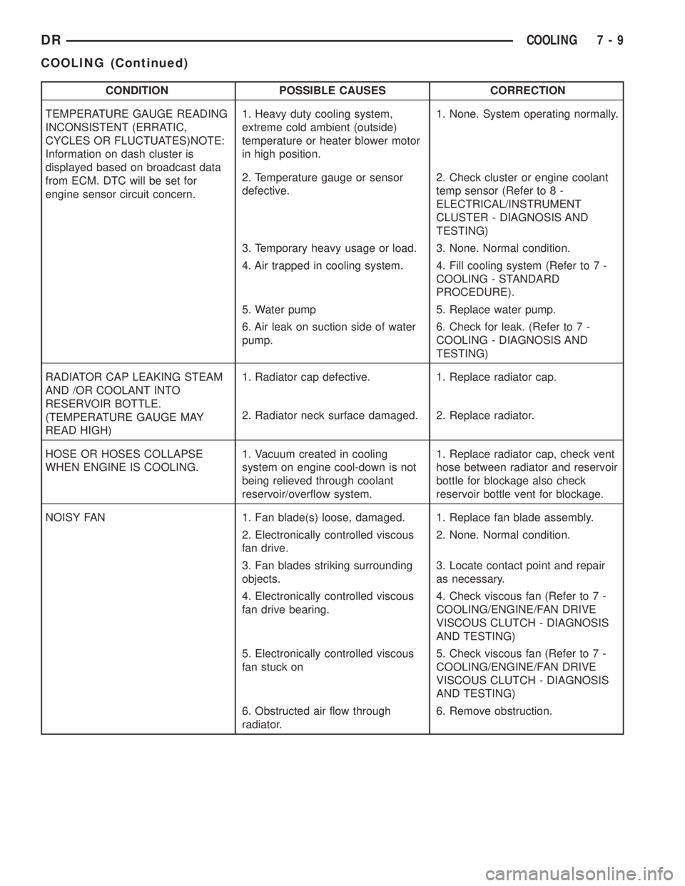
CONDITION POSSIBLE CAUSES CORRECTION
TEMPERATURE GAUGE READING
INCONSISTENT (ERRATIC,
CYCLES OR FLUCTUATES)NOTE:
Information on dash cluster is
displayed based on broadcast data
from ECM. DTC will be set for
engine sensor circuit concern.1. Heavy duty cooling system,
extreme cold ambient (outside)
temperature or heater blower motor
in high position.1. None. System operating normally.
2. Temperature gauge or sensor
defective.2. Check cluster or engine coolant
temp sensor (Refer to 8 -
ELECTRICAL/INSTRUMENT
CLUSTER - DIAGNOSIS AND
TESTING)
3. Temporary heavy usage or load. 3. None. Normal condition.
4. Air trapped in cooling system. 4. Fill cooling system (Refer to 7 -
COOLING - STANDARD
PROCEDURE).
5. Water pump 5. Replace water pump.
6. Air leak on suction side of water
pump.6. Check for leak. (Refer to 7 -
COOLING - DIAGNOSIS AND
TESTING)
RADIATOR CAP LEAKING STEAM
AND /OR COOLANT INTO
RESERVOIR BOTTLE.
(TEMPERATURE GAUGE MAY
READ HIGH)1. Radiator cap defective. 1. Replace radiator cap.
2. Radiator neck surface damaged. 2. Replace radiator.
HOSE OR HOSES COLLAPSE
WHEN ENGINE IS COOLING.1. Vacuum created in cooling
system on engine cool-down is not
being relieved through coolant
reservoir/overflow system.1. Replace radiator cap, check vent
hose between radiator and reservoir
bottle for blockage also check
reservoir bottle vent for blockage.
NOISY FAN 1. Fan blade(s) loose, damaged. 1. Replace fan blade assembly.
2. Electronically controlled viscous
fan drive.2. None. Normal condition.
3. Fan blades striking surrounding
objects.3. Locate contact point and repair
as necessary.
4. Electronically controlled viscous
fan drive bearing.4. Check viscous fan (Refer to 7 -
COOLING/ENGINE/FAN DRIVE
VISCOUS CLUTCH - DIAGNOSIS
AND TESTING)
5. Electronically controlled viscous
fan stuck on5. Check viscous fan (Refer to 7 -
COOLING/ENGINE/FAN DRIVE
VISCOUS CLUTCH - DIAGNOSIS
AND TESTING)
6. Obstructed air flow through
radiator.6. Remove obstruction.
DRCOOLING 7 - 9
COOLING (Continued)
Page 298 of 2895
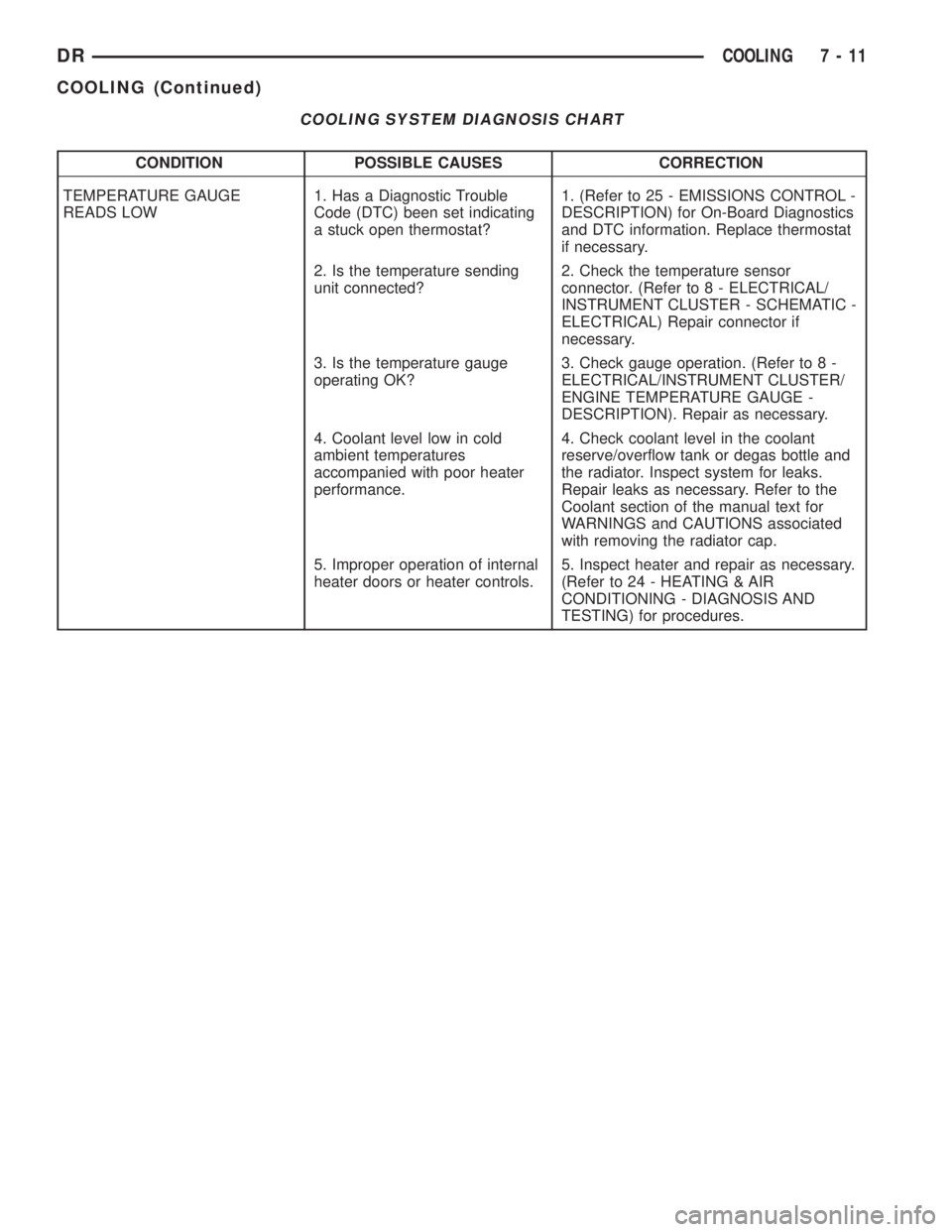
COOLING SYSTEM DIAGNOSIS CHART
CONDITION POSSIBLE CAUSES CORRECTION
TEMPERATURE GAUGE
READS LOW1. Has a Diagnostic Trouble
Code (DTC) been set indicating
a stuck open thermostat?1. (Refer to 25 - EMISSIONS CONTROL -
DESCRIPTION) for On-Board Diagnostics
and DTC information. Replace thermostat
if necessary.
2. Is the temperature sending
unit connected?2. Check the temperature sensor
connector. (Refer to 8 - ELECTRICAL/
INSTRUMENT CLUSTER - SCHEMATIC -
ELECTRICAL) Repair connector if
necessary.
3. Is the temperature gauge
operating OK?3. Check gauge operation. (Refer to 8 -
ELECTRICAL/INSTRUMENT CLUSTER/
ENGINE TEMPERATURE GAUGE -
DESCRIPTION). Repair as necessary.
4. Coolant level low in cold
ambient temperatures
accompanied with poor heater
performance.4. Check coolant level in the coolant
reserve/overflow tank or degas bottle and
the radiator. Inspect system for leaks.
Repair leaks as necessary. Refer to the
Coolant section of the manual text for
WARNINGS and CAUTIONS associated
with removing the radiator cap.
5. Improper operation of internal
heater doors or heater controls.5. Inspect heater and repair as necessary.
(Refer to 24 - HEATING & AIR
CONDITIONING - DIAGNOSIS AND
TESTING) for procedures.
DRCOOLING 7 - 11
COOLING (Continued)
Page 299 of 2895
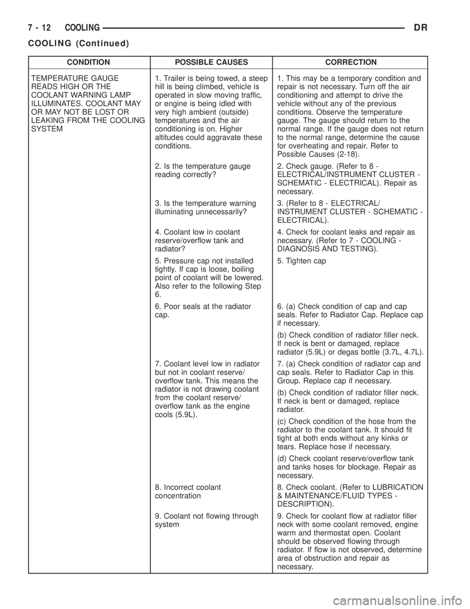
CONDITION POSSIBLE CAUSES CORRECTION
TEMPERATURE GAUGE
READS HIGH OR THE
COOLANT WARNING LAMP
ILLUMINATES. COOLANT MAY
OR MAY NOT BE LOST OR
LEAKING FROM THE COOLING
SYSTEM1. Trailer is being towed, a steep
hill is being climbed, vehicle is
operated in slow moving traffic,
or engine is being idled with
very high ambient (outside)
temperatures and the air
conditioning is on. Higher
altitudes could aggravate these
conditions.1. This may be a temporary condition and
repair is not necessary. Turn off the air
conditioning and attempt to drive the
vehicle without any of the previous
conditions. Observe the temperature
gauge. The gauge should return to the
normal range. If the gauge does not return
to the normal range, determine the cause
for overheating and repair. Refer to
Possible Causes (2-18).
2. Is the temperature gauge
reading correctly?2. Check gauge. (Refer to 8 -
ELECTRICAL/INSTRUMENT CLUSTER -
SCHEMATIC - ELECTRICAL). Repair as
necessary.
3. Is the temperature warning
illuminating unnecessarily?3. (Refer to 8 - ELECTRICAL/
INSTRUMENT CLUSTER - SCHEMATIC -
ELECTRICAL).
4. Coolant low in coolant
reserve/overflow tank and
radiator?4. Check for coolant leaks and repair as
necessary. (Refer to 7 - COOLING -
DIAGNOSIS AND TESTING).
5. Pressure cap not installed
tightly. If cap is loose, boiling
point of coolant will be lowered.
Also refer to the following Step
6.5. Tighten cap
6. Poor seals at the radiator
cap.6. (a) Check condition of cap and cap
seals. Refer to Radiator Cap. Replace cap
if necessary.
(b) Check condition of radiator filler neck.
If neck is bent or damaged, replace
radiator (5.9L) or degas bottle (3.7L, 4.7L).
7. Coolant level low in radiator
but not in coolant reserve/
overflow tank. This means the
radiator is not drawing coolant
from the coolant reserve/
overflow tank as the engine
cools (5.9L).7. (a) Check condition of radiator cap and
cap seals. Refer to Radiator Cap in this
Group. Replace cap if necessary.
(b) Check condition of radiator filler neck.
If neck is bent or damaged, replace
radiator.
(c) Check condition of the hose from the
radiator to the coolant tank. It should fit
tight at both ends without any kinks or
tears. Replace hose if necessary.
(d) Check coolant reserve/overflow tank
and tanks hoses for blockage. Repair as
necessary.
8. Incorrect coolant
concentration8. Check coolant. (Refer to LUBRICATION
& MAINTENANCE/FLUID TYPES -
DESCRIPTION).
9. Coolant not flowing through
system9. Check for coolant flow at radiator filler
neck with some coolant removed, engine
warm and thermostat open. Coolant
should be observed flowing through
radiator. If flow is not observed, determine
area of obstruction and repair as
necessary.
7 - 12 COOLINGDR
COOLING (Continued)
Page 301 of 2895
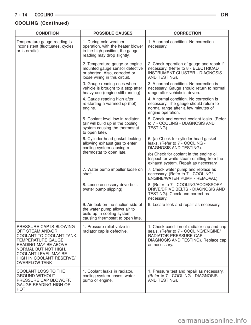
CONDITION POSSIBLE CAUSES CORRECTION
Temperature gauge reading is
inconsistent (flucttuates, cycles
or is erratic)1. During cold weather
operation, with the heater blower
in the high position, the gauge
reading may drop slightly.1. A normal condition. No correction
necessary.
2. Temperature gauge or engine
mounted gauge sensor defective
or shorted. Also, corroded or
loose wiring in this circuit.2. Check operation of gauge and repair if
necessary. (Refer to 8 - ELECTRICAL/
INSTRUMENT CLUSTER - DIAGNOSIS
AND TESTING).
3. Gauge reading rises when
vehicle is brought to a stop after
heavy use (engine still running)3. A normal condition. No correction is
necessary. Gauge should return to normal
range after vehicle is driven.
4. Gauge reading high after
re-starting a warmed up (hot)
engine.4. A normal condition. No correction is
necessary. The gauge should return to
normal range after a few minutes of
engine operation.
5. Coolant level low in radiator
(air will build up in the cooling
system causing the thermostat
to open late).5. Check and correct coolant leaks. (Refer
to 7 - COOLING - DIAGNOSIS AND
TESTING).
6. Cylinder head gasket leaking
allowing exhaust gas to enter
cooling system causing a
thermostat to open late.6. (a) Check for cylinder head gasket
leaks. (Refer to 7 - COOLING -
DIAGNOSIS AND TESTING).
(b) Check for coolant in the engine oil.
Inspect for white steam emitting from the
exhaust system. Repair as necessary.
7. Water pump impeller loose on
shaft.7. Check water pump and replace as
necessary. (Refer to 7 - COOLING/
ENGINE/WATER PUMP - REMOVAL).
8. Loose accessory drive belt.
(water pump slipping)8. (Refer to 7 - COOLING/ACCESSORY
DRIVE/DRIVE BELTS - DIAGNOSIS AND
TESTING). Check and correct as
necessary.
9. Air leak on the suction side of
the water pump allows air to
build up in cooling system
causing thermostat to open late.9. Locate leak and repair as necessary.
PRESSURE CAP IS BLOWING
OFF STEAM AND/OR
COOLANT TO COOLANT TANK.
TEMPERATURE GAUGE
READING MAY BE ABOVE
NORMAL BUT NOT HIGH.
COOLANT LEVEL MAY BE
HIGH IN COOLANT RESERVE/
OVERFLOW TANK1. Pressure relief valve in
radiator cap is defective.1. Check condition of radiator cap and cap
seals. (Refer to 7 - COOLING/ENGINE/
RADIATOR PRESSURE CAP -
DIAGNOSIS AND TESTING). Replace cap
as necessary.
COOLANT LOSS TO THE
GROUND WITHOUT
PRESSURE CAP BLOWOFF.
GAUGE READING HIGH OR
HOT1. Coolant leaks in radiator,
cooling system hoses, water
pump or engine.1. Pressure test and repair as necessary.
(Refer to 7 - COOLING - DIAGNOSIS
AND TESTING).
7 - 14 COOLINGDR
COOLING (Continued)
Page 364 of 2895
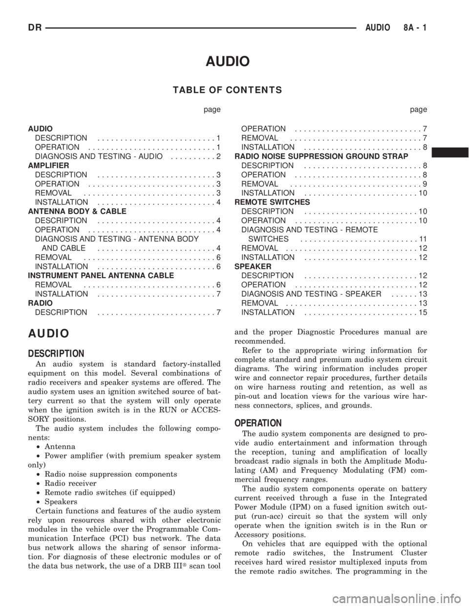
AUDIO
TABLE OF CONTENTS
page page
AUDIO
DESCRIPTION..........................1
OPERATION............................1
DIAGNOSIS AND TESTING - AUDIO..........2
AMPLIFIER
DESCRIPTION..........................3
OPERATION............................3
REMOVAL.............................3
INSTALLATION..........................4
ANTENNA BODY & CABLE
DESCRIPTION..........................4
OPERATION............................4
DIAGNOSIS AND TESTING - ANTENNA BODY
AND CABLE..........................4
REMOVAL.............................6
INSTALLATION..........................6
INSTRUMENT PANEL ANTENNA CABLE
REMOVAL.............................6
INSTALLATION..........................7
RADIO
DESCRIPTION..........................7OPERATION............................7
REMOVAL.............................7
INSTALLATION..........................8
RADIO NOISE SUPPRESSION GROUND STRAP
DESCRIPTION..........................8
OPERATION............................8
REMOVAL.............................9
INSTALLATION.........................10
REMOTE SWITCHES
DESCRIPTION.........................10
OPERATION...........................10
DIAGNOSIS AND TESTING - REMOTE
SWITCHES..........................11
REMOVAL.............................12
INSTALLATION.........................12
SPEAKER
DESCRIPTION.........................12
OPERATION...........................12
DIAGNOSIS AND TESTING - SPEAKER......13
REMOVAL.............................13
INSTALLATION.........................15
AUDIO
DESCRIPTION
An audio system is standard factory-installed
equipment on this model. Several combinations of
radio receivers and speaker systems are offered. The
audio system uses an ignition switched source of bat-
tery current so that the system will only operate
when the ignition switch is in the RUN or ACCES-
SORY positions.
The audio system includes the following compo-
nents:
²Antenna
²Power amplifier (with premium speaker system
only)
²Radio noise suppression components
²Radio receiver
²Remote radio switches (if equipped)
²Speakers
Certain functions and features of the audio system
rely upon resources shared with other electronic
modules in the vehicle over the Programmable Com-
munication Interface (PCI) bus network. The data
bus network allows the sharing of sensor informa-
tion. For diagnosis of these electronic modules or of
the data bus network, the use of a DRB IIItscan tooland the proper Diagnostic Procedures manual are
recommended.
Refer to the appropriate wiring information for
complete standard and premium audio system circuit
diagrams. The wiring information includes proper
wire and connector repair procedures, further details
on wire harness routing and retention, as well as
pin-out and location views for the various wire har-
ness connectors, splices, and grounds.
OPERATION
The audio system components are designed to pro-
vide audio entertainment and information through
the reception, tuning and amplification of locally
broadcast radio signals in both the Amplitude Modu-
lating (AM) and Frequency Modulating (FM) com-
mercial frequency ranges.
The audio system components operate on battery
current received through a fuse in the Integrated
Power Module (IPM) on a fused ignition switch out-
put (run-acc) circuit so that the system will only
operate when the ignition switch is in the Run or
Accessory positions.
On vehicles that are equipped with the optional
remote radio switches, the Instrument Cluster
receives hard wired resistor multiplexed inputs from
the remote radio switches. The programming in the
DRAUDIO 8A - 1
Page 365 of 2895
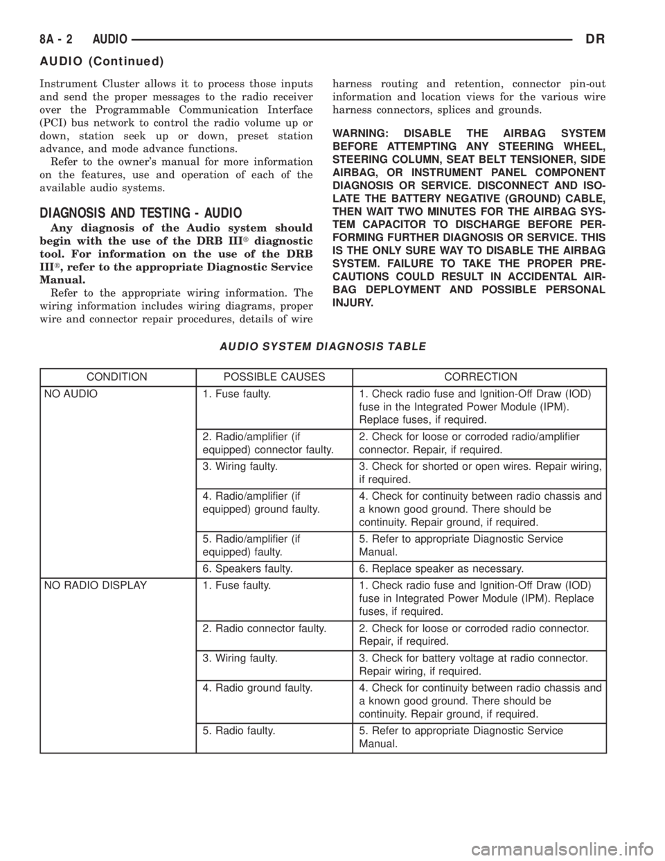
Instrument Cluster allows it to process those inputs
and send the proper messages to the radio receiver
over the Programmable Communication Interface
(PCI) bus network to control the radio volume up or
down, station seek up or down, preset station
advance, and mode advance functions.
Refer to the owner's manual for more information
on the features, use and operation of each of the
available audio systems.
DIAGNOSIS AND TESTING - AUDIO
Any diagnosis of the Audio system should
begin with the use of the DRB IIItdiagnostic
tool. For information on the use of the DRB
IIIt, refer to the appropriate Diagnostic Service
Manual.
Refer to the appropriate wiring information. The
wiring information includes wiring diagrams, proper
wire and connector repair procedures, details of wireharness routing and retention, connector pin-out
information and location views for the various wire
harness connectors, splices and grounds.
WARNING: DISABLE THE AIRBAG SYSTEM
BEFORE ATTEMPTING ANY STEERING WHEEL,
STEERING COLUMN, SEAT BELT TENSIONER, SIDE
AIRBAG, OR INSTRUMENT PANEL COMPONENT
DIAGNOSIS OR SERVICE. DISCONNECT AND ISO-
LATE THE BATTERY NEGATIVE (GROUND) CABLE,
THEN WAIT TWO MINUTES FOR THE AIRBAG SYS-
TEM CAPACITOR TO DISCHARGE BEFORE PER-
FORMING FURTHER DIAGNOSIS OR SERVICE. THIS
IS THE ONLY SURE WAY TO DISABLE THE AIRBAG
SYSTEM. FAILURE TO TAKE THE PROPER PRE-
CAUTIONS COULD RESULT IN ACCIDENTAL AIR-
BAG DEPLOYMENT AND POSSIBLE PERSONAL
INJURY.
AUDIO SYSTEM DIAGNOSIS TABLE
CONDITION POSSIBLE CAUSES CORRECTION
NO AUDIO 1. Fuse faulty. 1. Check radio fuse and Ignition-Off Draw (IOD)
fuse in the Integrated Power Module (IPM).
Replace fuses, if required.
2. Radio/amplifier (if
equipped) connector faulty.2. Check for loose or corroded radio/amplifier
connector. Repair, if required.
3. Wiring faulty. 3. Check for shorted or open wires. Repair wiring,
if required.
4. Radio/amplifier (if
equipped) ground faulty.4. Check for continuity between radio chassis and
a known good ground. There should be
continuity. Repair ground, if required.
5. Radio/amplifier (if
equipped) faulty.5. Refer to appropriate Diagnostic Service
Manual.
6. Speakers faulty. 6. Replace speaker as necessary.
NO RADIO DISPLAY 1. Fuse faulty. 1. Check radio fuse and Ignition-Off Draw (IOD)
fuse in Integrated Power Module (IPM). Replace
fuses, if required.
2. Radio connector faulty. 2. Check for loose or corroded radio connector.
Repair, if required.
3. Wiring faulty. 3. Check for battery voltage at radio connector.
Repair wiring, if required.
4. Radio ground faulty. 4. Check for continuity between radio chassis and
a known good ground. There should be
continuity. Repair ground, if required.
5. Radio faulty. 5. Refer to appropriate Diagnostic Service
Manual.
8A - 2 AUDIODR
AUDIO (Continued)
Page 380 of 2895
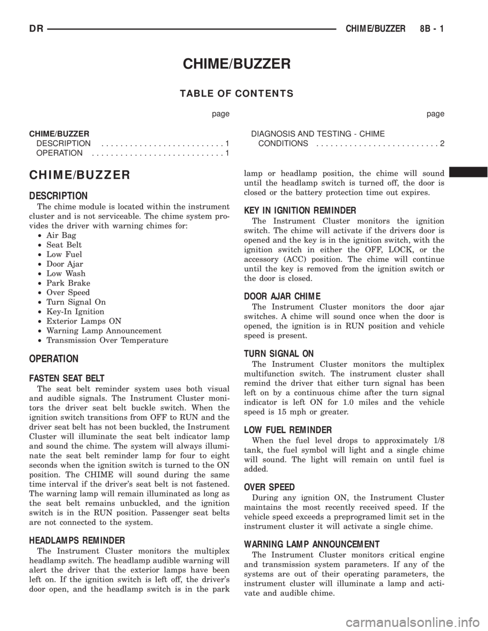
CHIME/BUZZER
TABLE OF CONTENTS
page page
CHIME/BUZZER
DESCRIPTION..........................1
OPERATION............................1DIAGNOSIS AND TESTING - CHIME
CONDITIONS..........................2
CHIME/BUZZER
DESCRIPTION
The chime module is located within the instrument
cluster and is not serviceable. The chime system pro-
vides the driver with warning chimes for:
²Air Bag
²Seat Belt
²Low Fuel
²Door Ajar
²Low Wash
²Park Brake
²Over Speed
²Turn Signal On
²Key-In Ignition
²Exterior Lamps ON
²Warning Lamp Announcement
²Transmission Over Temperature
OPERATION
FASTEN SEAT BELT
The seat belt reminder system uses both visual
and audible signals. The Instrument Cluster moni-
tors the driver seat belt buckle switch. When the
ignition switch transitions from OFF to RUN and the
driver seat belt has not been buckled, the Instrument
Cluster will illuminate the seat belt indicator lamp
and sound the chime. The system will always illumi-
nate the seat belt reminder lamp for four to eight
seconds when the ignition switch is turned to the ON
position. The CHIME will sound during the same
time interval if the driver's seat belt is not fastened.
The warning lamp will remain illuminated as long as
the seat belt remains unbuckled, and the ignition
switch is in the RUN position. Passenger seat belts
are not connected to the system.
HEADLAMPS REMINDER
The Instrument Cluster monitors the multiplex
headlamp switch. The headlamp audible warning will
alert the driver that the exterior lamps have been
left on. If the ignition switch is left off, the driver's
door open, and the headlamp switch is in the parklamp or headlamp position, the chime will sound
until the headlamp switch is turned off, the door is
closed or the battery protection time out expires.
KEY IN IGNITION REMINDER
The Instrument Cluster monitors the ignition
switch. The chime will activate if the drivers door is
opened and the key is in the ignition switch, with the
ignition switch in either the OFF, LOCK, or the
accessory (ACC) position. The chime will continue
until the key is removed from the ignition switch or
the door is closed.
DOOR AJAR CHIME
The Instrument Cluster monitors the door ajar
switches. A chime will sound once when the door is
opened, the ignition is in RUN position and vehicle
speed is present.
TURN SIGNAL ON
The Instrument Cluster monitors the multiplex
multifunction switch. The instrument cluster shall
remind the driver that either turn signal has been
left on by a continuous chime after the turn signal
indicator is left ON for 1.0 miles and the vehicle
speed is 15 mph or greater.
LOW FUEL REMINDER
When the fuel level drops to approximately 1/8
tank, the fuel symbol will light and a single chime
will sound. The light will remain on until fuel is
added.
OVER SPEED
During any ignition ON, the Instrument Cluster
maintains the most recently received speed. If the
vehicle speed exceeds a preprogramed limit set in the
instrument cluster it will activate a single chime.
WARNING LAMP ANNOUNCEMENT
The Instrument Cluster monitors critical engine
and transmission system parameters. If any of the
systems are out of their operating parameters, the
instrument cluster will illuminate a lamp and acti-
vate and audible chime.
DRCHIME/BUZZER 8B - 1