key DODGE RAM 2003 Service Repair Manual
[x] Cancel search | Manufacturer: DODGE, Model Year: 2003, Model line: RAM, Model: DODGE RAM 2003Pages: 2895, PDF Size: 83.15 MB
Page 29 of 2895
A towed vehicle should be raised until lifted wheels
are a minimum 100 mm (4 in) from the ground. Be
sure there is adequate ground clearance at the oppo-
site end of the vehicle, especially when towing over
rough terrain or steep rises in the road. If necessary,
remove the wheels from the lifted end of the vehicle
and lower the vehicle closer to the ground, to
increase the ground clearance at the opposite end of
the vehicle. Install lug nuts on wheel attaching studs
to retain brake drums or rotors.
RAMP ANGLE
If a vehicle with flat-bed towing equipment is used,
the approach ramp angle should not exceed 15
degrees.
TOWING WHEN KEYS ARE NOT AVAILABLE
When the vehicle is locked and keys are not avail-
able, use a flat bed hauler. A Wheel-lift or Sling-type
device can be used on 4WD vehicles providedall the
wheels are lifted off the ground using tow dol-
lies.
FOUR-WHEEL-DRIVE VEHICLE TOWING
Chrysler Corporation recommends that a vehicle be
transported on a flat-bed device. A Wheel-lift or
Sling-type device can be used providedall the
wheels are lifted off the ground using tow dol-
lies.
WARNING: WHEN TOWING A DISABLED VEHICLE
AND THE DRIVE WHEELS ARE SECURED IN A
WHEEL LIFT OR TOW DOLLIES, ENSURE THE
TRANSMISSION IS IN THE PARK POSITION (AUTO-
MATIC TRANSMISSION) OR A FORWARD DRIVE
GEAR (MANUAL TRANSMISSION).
CAUTION: Many vehicles are equipped with air
dams, spoilers, and/or ground effect panels. To
avoid component damage, a wheel-lift towing vehi-
cle or a flat-bed hauling vehicle is recommended.
0 - 16 LUBRICATION & MAINTENANCEDR
TOWING (Continued)
Page 185 of 2895
AXLE BEARINGS
REMOVAL
(1) Remove axle shaft flange bolts and remove axle
shaft.
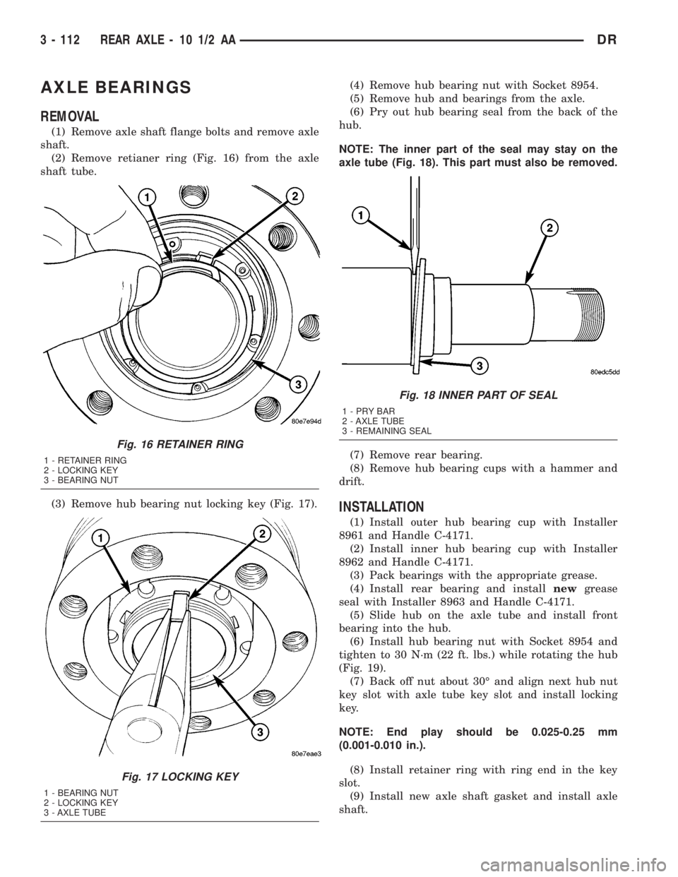
(2) Remove retianer ring (Fig. 16) from the axle
shaft tube.
(3) Remove hub bearing nut locking key (Fig. 17).(4) Remove hub bearing nut with Socket 8954.
(5) Remove hub and bearings from the axle.
(6) Pry out hub bearing seal from the back of the
hub.
NOTE: The inner part of the seal may stay on the
axle tube (Fig. 18). This part must also be removed.
(7) Remove rear bearing.
(8) Remove hub bearing cups with a hammer and
drift.
INSTALLATION
(1) Install outer hub bearing cup with Installer
8961 and Handle C-4171.
(2) Install inner hub bearing cup with Installer
8962 and Handle C-4171.
(3) Pack bearings with the appropriate grease.
(4) Install rear bearing and installnewgrease
seal with Installer 8963 and Handle C-4171.
(5) Slide hub on the axle tube and install front
bearing into the hub.
(6) Install hub bearing nut with Socket 8954 and
tighten to 30 N´m (22 ft. lbs.) while rotating the hub
(Fig. 19).
(7) Back off nut about 30É and align next hub nut
key slot with axle tube key slot and install locking
key.
NOTE: End play should be 0.025-0.25 mm
(0.001-0.010 in.).
(8) Install retainer ring with ring end in the key
slot.
(9) Install new axle shaft gasket and install axle
shaft.
Fig. 16 RETAINER RING
1 - RETAINER RING
2 - LOCKING KEY
3 - BEARING NUT
Fig. 17 LOCKING KEY
1 - BEARING NUT
2 - LOCKING KEY
3 - AXLE TUBE
Fig. 18 INNER PART OF SEAL
1-PRYBAR
2 - AXLE TUBE
3 - REMAINING SEAL
3 - 112 REAR AXLE - 10 1/2 AADR
Page 211 of 2895
AXLE SHAFTS
REMOVAL
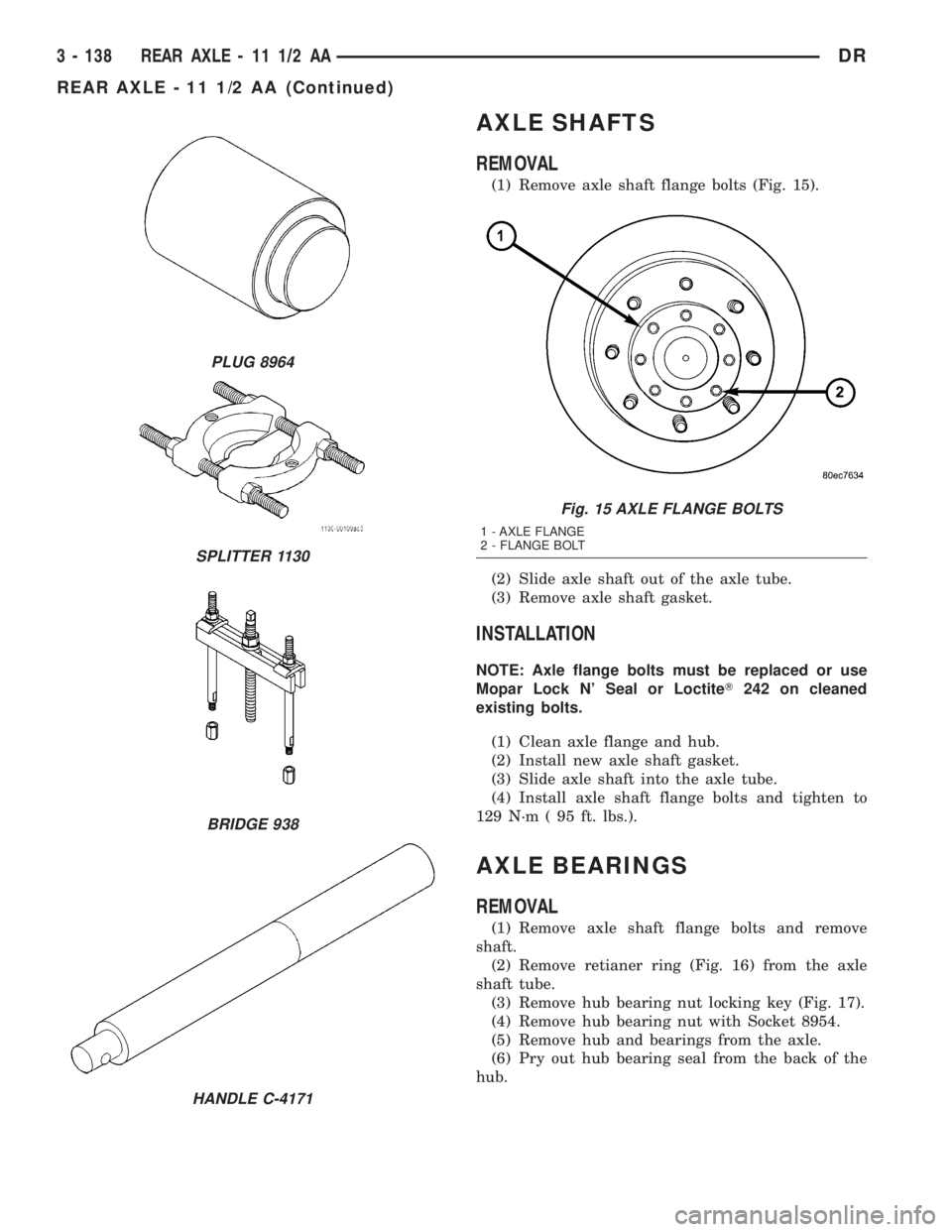
(1) Remove axle shaft flange bolts (Fig. 15).
(2) Slide axle shaft out of the axle tube.
(3) Remove axle shaft gasket.
INSTALLATION
NOTE: Axle flange bolts must be replaced or use
Mopar Lock N' Seal or LoctiteT242 on cleaned
existing bolts.
(1) Clean axle flange and hub.
(2) Install new axle shaft gasket.
(3) Slide axle shaft into the axle tube.
(4) Install axle shaft flange bolts and tighten to
129 N´m ( 95 ft. lbs.).
AXLE BEARINGS
REMOVAL
(1) Remove axle shaft flange bolts and remove
shaft.
(2) Remove retianer ring (Fig. 16) from the axle
shaft tube.
(3) Remove hub bearing nut locking key (Fig. 17).
(4) Remove hub bearing nut with Socket 8954.
(5) Remove hub and bearings from the axle.
(6) Pry out hub bearing seal from the back of the
hub.
PLUG 8964
SPLITTER 1130
BRIDGE 938
HANDLE C-4171
Fig. 15 AXLE FLANGE BOLTS
1 - AXLE FLANGE
2 - FLANGE BOLT
3 - 138 REAR AXLE - 11 1/2 AADR
REAR AXLE - 11 1/2 AA (Continued)
Page 212 of 2895
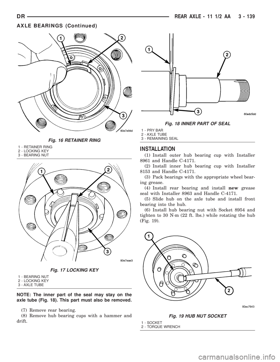
NOTE: The inner part of the seal may stay on the
axle tube (Fig. 18). This part must also be removed.
(7) Remove rear bearing.
(8) Remove hub bearing cups with a hammer and
drift.
INSTALLATION
(1) Install outer hub bearing cup with Installer
8961 and Handle C-4171.
(2) Install inner hub bearing cup with Installer
8153 and Handle C-4171.
(3) Pack bearings with the appropriate wheel bear-
ing grease.
(4) Install rear bearing and installnewgrease
seal with Installer 8963 and Handle C-4171.
(5) Slide hub on the axle tube and install front
bearing into the hub.
(6) Install hub bearing nut with Socket 8954 and
tighten to 30 N´m (22 ft. lbs.) while rotating the hub
(Fig. 19).
Fig. 16 RETAINER RING
1 - RETAINER RING
2 - LOCKING KEY
3 - BEARING NUT
Fig. 17 LOCKING KEY
1 - BEARING NUT
2 - LOCKING KEY
3 - AXLE TUBE
Fig. 18 INNER PART OF SEAL
1-PRYBAR
2 - AXLE TUBE
3 - REMAINING SEAL
Fig. 19 HUB NUT SOCKET
1 - SOCKET
2 - TORQUE WRENCH
DRREAR AXLE - 11 1/2 AA 3 - 139
AXLE BEARINGS (Continued)
Page 213 of 2895
(7) Back off nut about 30É and align next hub nut
key slot with axle tube key slot and install locking
key.
NOTE: End play should be 0.025-0.25 mm
(0.01-0.001 in.)
(8) Install retainer ring with ring end in the key
slot.
(9) Install new axle shaft gasket and install the
axle shaft.
PINION SEAL
REMOVAL
(1) Remove axle shafts.
(2) Mark the propeller shaft and pinion flange for
installation reference.
(3) Remove propeller shaft.
(4) Rotate pinion gear three or four times.
(5) Measure and record the amount of torque nec-
essary to rotate the pinion gear with an inch pound
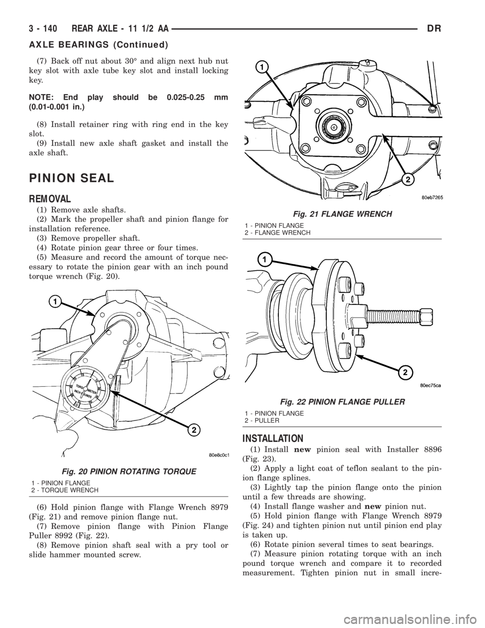
torque wrench (Fig. 20).
(6) Hold pinion flange with Flange Wrench 8979
(Fig. 21) and remove pinion flange nut.
(7) Remove pinion flange with Pinion Flange
Puller 8992 (Fig. 22).
(8) Remove pinion shaft seal with a pry tool or
slide hammer mounted screw.
INSTALLATION
(1) Installnewpinion seal with Installer 8896
(Fig. 23).
(2) Apply a light coat of teflon sealant to the pin-
ion flange splines.
(3) Lightly tap the pinion flange onto the pinion
until a few threads are showing.
(4) Install flange washer andnewpinion nut.
(5) Hold pinion flange with Flange Wrench 8979
(Fig. 24) and tighten pinion nut until pinion end play
is taken up.
(6) Rotate pinion several times to seat bearings.
(7) Measure pinion rotating torque with an inch
pound torque wrench and compare it to recorded
measurement. Tighten pinion nut in small incre-
Fig. 20 PINION ROTATING TORQUE
1 - PINION FLANGE
2 - TORQUE WRENCH
Fig. 21 FLANGE WRENCH
1 - PINION FLANGE
2 - FLANGE WRENCH
Fig. 22 PINION FLANGE PULLER
1 - PINION FLANGE
2 - PULLER
3 - 140 REAR AXLE - 11 1/2 AADR
AXLE BEARINGS (Continued)
Page 331 of 2895
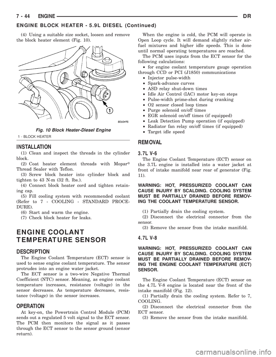
(4) Using a suitable size socket, loosen and remove
the block heater element (Fig. 10).
INSTALLATION
(1) Clean and inspect the threads in the cylinder
block.
(2) Coat heater element threads with Mopart
Thread Sealer with Teflon.
(3) Screw block heater into cylinder block and
tighten to 43 N´m (32 ft. lbs.).
(4) Connect block heater cord and tighten retain-
ing cap.
(5) Fill cooling system with recommended coolant
(Refer to 7 - COOLING - STANDARD PROCE-
DURE).
(6) Start and warm the engine.
(7) Check block heater for leaks.
ENGINE COOLANT
TEMPERATURE SENSOR
DESCRIPTION
The Engine Coolant Temperature (ECT) sensor is
used to sense engine coolant temperature. The sensor
protrudes into an engine water jacket.
The ECT sensor is a two-wire Negative Thermal
Coefficient (NTC) sensor. Meaning, as engine coolant
temperature increases, resistance (voltage) in the
sensor decreases. As temperature decreases, resis-
tance (voltage) in the sensor increases.
OPERATION
At key-on, the Powertrain Control Module (PCM)
sends out a regulated 5 volt signal to the ECT sensor.
The PCM then monitors the signal as it passes
through the ECT sensor to the sensor ground (sensor
return).When the engine is cold, the PCM will operate in
Open Loop cycle. It will demand slightly richer air-
fuel mixtures and higher idle speeds. This is done
until normal operating temperatures are reached.
The PCM uses inputs from the ECT sensor for the
following calculations:
²for engine coolant temperature gauge operation
through CCD or PCI (J1850) communications
²Injector pulse-width
²Spark-advance curves
²ASD relay shut-down times
²Idle Air Control (IAC) motor key-on steps
²Pulse-width prime-shot during cranking
²O2 sensor closed loop times
²Purge solenoid on/off times
²EGR solenoid on/off times (if equipped)
²Leak Detection Pump operation (if equipped)
²Radiator fan relay on/off times (if equipped)
²Target idle speed
REMOVAL
3.7L V-6
The Engine Coolant Temperature (ECT) sensor on
the 3.7L engine is installed into a water jacket at
front of intake manifold near rear of generator (Fig.
11).
WARNING: HOT, PRESSURIZED COOLANT CAN
CAUSE INJURY BY SCALDING. COOLING SYSTEM
MUST BE PARTIALLY DRAINED BEFORE REMOV-
ING THE COOLANT TEMPERATURE SENSOR.
(1) Partially drain the cooling system.
(2) Disconnect the electrical connector from the
sensor.
(3) Remove the sensor from the intake manifold.
4.7L V-8
WARNING: HOT, PRESSURIZED COOLANT CAN
CAUSE INJURY BY SCALDING. COOLING SYSTEM
MUST BE PARTIALLY DRAINED BEFORE REMOV-
ING THE ENGINE COOLANT TEMPERATURE (ECT)
SENSOR.
The Engine Coolant Temperature (ECT) sensor on
the 4.7L V-8 engine is located near the front of the
intake manifold (Fig. 12).
(1) Partially drain the cooling system. Refer to 7,
COOLING.
(2) Disconnect the electrical connector from the
ECT sensor.
(3) Remove the sensor from the intake manifold.
Fig. 10 Block Heater-Diesel Engine
1 - BLOCK HEATER
7 - 44 ENGINEDR
ENGINE BLOCK HEATER - 5.9L DIESEL (Continued)
Page 371 of 2895
INSTALLATION
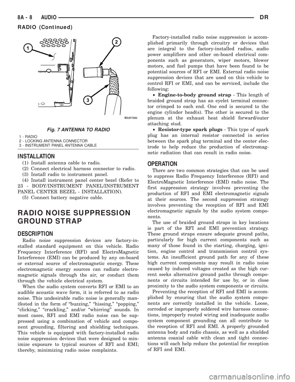
(1) Install antenna cable to radio.
(2) Connect electrical harness connector to radio.
(3) Install radio to instrument panel.
(4) Install instrument panel center bezel (Refer to
23 - BODY/INSTRUMENT PANEL/INSTRUMENT
PANEL CENTER BEZEL - INSTALLATION).
(5) Connect battery negative cable.
RADIO NOISE SUPPRESSION
GROUND STRAP
DESCRIPTION
Radio noise suppression devices are factory-in-
stalled standard equipment on this vehicle. Radio
Frequency Interference (RFI) and ElectroMagnetic
Interference (EMI) can be produced by any on-board
or external source of electromagnetic energy. These
electromagnetic energy sources can radiate electro-
magnetic signals through the air, or conduct them
through the vehicle electrical system.
When the audio system converts RFI or EMI to an
audible acoustic wave form, it is referred to as radio
noise. This undesirable radio noise is generally man-
ifested in the form of ªbuzzing,º ªhissing,º ªpopping,º
ªclicking,º ªcrackling,º and/or ªwhirringº sounds. In
most cases, RFI and EMI radio noise can be sup-
pressed using a combination of vehicle and compo-
nent grounding, filtering and shielding techniques.
This vehicle is equipped with factory-installed radio
noise suppression devices that were designed to min-
imize exposure to typical sources of RFI and EMI;
thereby, minimizing radio noise complaints.Factory-installed radio noise suppression is accom-
plished primarily through circuitry or devices that
are integral to the factory-installed radios, audio
power amplifiers and other on-board electrical com-
ponents such as generators, wiper motors, blower
motors, and fuel pumps that have been found to be
potential sources of RFI or EMI. External radio noise
suppression devices that are used on this vehicle to
control RFI or EMI, and can be serviced, include the
following:
²Engine-to-body ground strap- This length of
braided ground strap has an eyelet terminal connec-
tor crimped to each end. One end is secured to the
engine cylinder head(s). The other is secured to the
plenum at the exhaust heat shield forward/outer
attaching stud.
²Resistor-type spark plugs- This type of spark
plug has an internal resistor connected in series
between the spark plug terminal and the center elec-
trode to help reduce the production of electromag-
netic radiation that can result in radio noise.
OPERATION
There are two common strategies that can be used
to suppress Radio Frequency Interference (RFI) and
ElectroMagnetic Interference (EMI) radio noise. The
first suppression strategy involves preventing the
production of RFI and EMI electromagnetic signals
at their sources. The second suppression strategy
involves preventing the reception of RFI and EMI
electromagnetic signals by the audio system compo-
nents.
The use of braided ground straps in key locations
is part of the RFI and EMI prevention strategy.
These ground straps ensure adequate ground paths,
particularly for high current components such as
many of those found in the starting, charging, igni-
tion, engine control and transmission control sys-
tems. An insufficient ground path for any of these
high current components may result in radio noise
caused by induced voltages created as the high cur-
rent seeks alternative ground paths through compo-
nents or circuits intended for use by, or in close
proximity to the audio system components or circuits.
Preventing the reception of RFI and EMI is accom-
plished by ensuring that the audio system compo-
nents are correctly installed in the vehicle. Loose,
corroded or improperly soldered wire harness connec-
tions, improperly routed wiring and inadequate audio
system component grounding can all contribute to
the reception of RFI and EMI. A properly grounded
antenna body and radio chassis, as well as a shielded
antenna coaxial cable with clean and tight connec-
tions will each help reduce the potential for reception
of RFI and EMI.
Fig. 7 ANTENNA TO RADIO
1 - RADIO
2 - LOCKING ANTENNA CONNECTOR
3 - INSTRUMENT PANEL ANTENNA CABLE
8A - 8 AUDIODR
RADIO (Continued)
Page 380 of 2895
CHIME/BUZZER
TABLE OF CONTENTS
page page
CHIME/BUZZER
DESCRIPTION..........................1
OPERATION............................1DIAGNOSIS AND TESTING - CHIME
CONDITIONS..........................2
CHIME/BUZZER
DESCRIPTION
The chime module is located within the instrument
cluster and is not serviceable. The chime system pro-
vides the driver with warning chimes for:
²Air Bag
²Seat Belt
²Low Fuel
²Door Ajar
²Low Wash
²Park Brake
²Over Speed
²Turn Signal On
²Key-In Ignition
²Exterior Lamps ON
²Warning Lamp Announcement
²Transmission Over Temperature
OPERATION
FASTEN SEAT BELT
The seat belt reminder system uses both visual
and audible signals. The Instrument Cluster moni-
tors the driver seat belt buckle switch. When the
ignition switch transitions from OFF to RUN and the
driver seat belt has not been buckled, the Instrument
Cluster will illuminate the seat belt indicator lamp
and sound the chime. The system will always illumi-
nate the seat belt reminder lamp for four to eight
seconds when the ignition switch is turned to the ON
position. The CHIME will sound during the same
time interval if the driver's seat belt is not fastened.
The warning lamp will remain illuminated as long as
the seat belt remains unbuckled, and the ignition
switch is in the RUN position. Passenger seat belts
are not connected to the system.
HEADLAMPS REMINDER
The Instrument Cluster monitors the multiplex
headlamp switch. The headlamp audible warning will
alert the driver that the exterior lamps have been
left on. If the ignition switch is left off, the driver's
door open, and the headlamp switch is in the parklamp or headlamp position, the chime will sound
until the headlamp switch is turned off, the door is
closed or the battery protection time out expires.
KEY IN IGNITION REMINDER
The Instrument Cluster monitors the ignition
switch. The chime will activate if the drivers door is
opened and the key is in the ignition switch, with the
ignition switch in either the OFF, LOCK, or the
accessory (ACC) position. The chime will continue
until the key is removed from the ignition switch or
the door is closed.
DOOR AJAR CHIME
The Instrument Cluster monitors the door ajar
switches. A chime will sound once when the door is
opened, the ignition is in RUN position and vehicle
speed is present.
TURN SIGNAL ON
The Instrument Cluster monitors the multiplex
multifunction switch. The instrument cluster shall
remind the driver that either turn signal has been
left on by a continuous chime after the turn signal
indicator is left ON for 1.0 miles and the vehicle
speed is 15 mph or greater.
LOW FUEL REMINDER
When the fuel level drops to approximately 1/8
tank, the fuel symbol will light and a single chime
will sound. The light will remain on until fuel is
added.
OVER SPEED
During any ignition ON, the Instrument Cluster
maintains the most recently received speed. If the
vehicle speed exceeds a preprogramed limit set in the
instrument cluster it will activate a single chime.
WARNING LAMP ANNOUNCEMENT
The Instrument Cluster monitors critical engine
and transmission system parameters. If any of the
systems are out of their operating parameters, the
instrument cluster will illuminate a lamp and acti-
vate and audible chime.
DRCHIME/BUZZER 8B - 1
Page 382 of 2895
ELECTRONIC CONTROL MODULES
TABLE OF CONTENTS
page page
COMMUNICATION
DESCRIPTION..........................1
OPERATION............................2
CONTROLLER ANTILOCK BRAKE
DESCRIPTION..........................3
OPERATION............................3
REMOVAL.............................3
INSTALLATION..........................3
DATA LINK CONNECTOR
DESCRIPTION - DATA LINK CONNECTOR.....3
OPERATION - DATA LINK CONNECTOR......3
ENGINE CONTROL MODULE
DESCRIPTION - ECM.....................4
OPERATION - ECM......................4
REMOVAL.............................4
INSTALLATION..........................5
FRONT CONTROL MODULE
DESCRIPTION..........................5
OPERATION............................5
DIAGNOSIS AND TESTING - FRONT
CONTROL MODULE....................6
REMOVAL.............................6
INSTALLATION..........................6
HEATED SEAT MODULE
DESCRIPTION..........................6
OPERATION............................6
DIAGNOSIS AND TESTING - HEATED SEAT
MODULE.............................7
REMOVAL.............................7
INSTALLATION..........................7
POWERTRAIN CONTROL MODULE
DESCRIPTION
DESCRIPTION - PCM...................8DESCRIPTION - MODES OF OPERATION....8
DESCRIPTION - 5 VOLT SUPPLIES.......10
DESCRIPTION - IGNITION CIRCUIT SENSE . 10
DESCRIPTION - POWER GROUNDS......10
DESCRIPTION - SENSOR RETURN.......10
OPERATION
OPERATION - PCM....................11
OPERATION - 5 VOLT SUPPLIES.........11
OPERATION - IGNITION CIRCUIT SENSE . . . 12
REMOVAL.............................12
INSTALLATION.........................12
SENTRY KEY IMMOBILIZER MODULE
DESCRIPTION.........................13
OPERATION...........................13
STANDARD PROCEDURE - PCM/SKIM
PROGRAMMING......................14
REMOVAL.............................15
INSTALLATION.........................15
TRANSFER CASE CONTROL MODULE
DESCRIPTION.........................15
OPERATION...........................15
TRANSMISSION CONTROL MODULE
DESCRIPTION.........................19
OPERATION...........................19
STANDARD PROCEDURE
STANDARD PROCEDURE - TCM QUICK
LEARN..............................21
STANDARD PROCEDURE - DRIVE LEARN . . 21
COMMUNICATION
DESCRIPTION
The DaimlerChrysler Programmable Communica-
tion Interface (PCI) data bus system is a single wire
multiplex system used for vehicle communications on
many DaimlerChrysler Corporation vehicles. Multi-plexing is a system that enables the transmission of
several messages over a single channel or circuit. All
DaimlerChrysler vehicles use this principle for com-
munication between various microprocessor-based
electronic control modules. The PCI data bus exceeds
the Society of Automotive Engineers (SAE) J1850
Standard for Class B Multiplexing.
DRELECTRONIC CONTROL MODULES 8E - 1
Page 386 of 2895
To avoid possible voltage spike damage to either
the Engine Control Module ECM, ignition key must
be off, and negative battery cables must be discon-
nected before unplugging ECM connectors.
(2) Disconnect both negative battery cables at both
batteries.
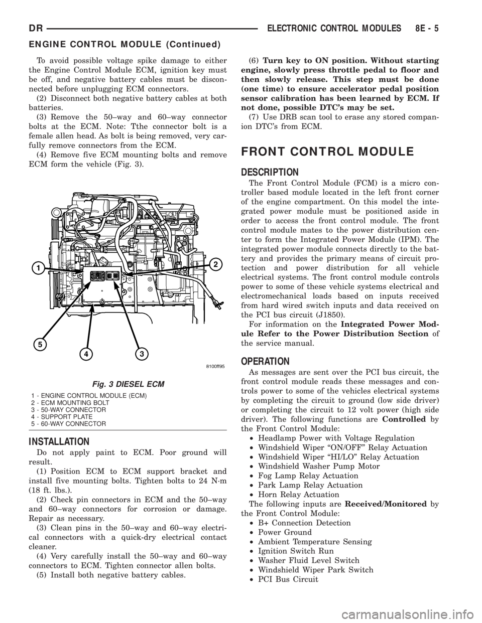
(3) Remove the 50±way and 60±way connector
bolts at the ECM. Note: Tthe connector bolt is a
female allen head. As bolt is being removed, very car-
fully remove connectors from the ECM.
(4) Remove five ECM mounting bolts and remove
ECM form the vehicle (Fig. 3).
INSTALLATION
Do not apply paint to ECM. Poor ground will
result.
(1) Position ECM to ECM support bracket and
install five mounting bolts. Tighten bolts to 24 N´m
(18 ft. lbs.).
(2) Check pin connectors in ECM and the 50±way
and 60±way connectors for corrosion or damage.
Repair as necessary.
(3) Clean pins in the 50±way and 60±way electri-
cal connectors with a quick-dry electrical contact
cleaner.
(4) Very carefully install the 50±way and 60±way
connectors to ECM. Tighten connector allen bolts.
(5) Install both negative battery cables.(6)Turn key to ON position. Without starting
engine, slowly press throttle pedal to floor and
then slowly release. This step must be done
(one time) to ensure accelerator pedal position
sensor calibration has been learned by ECM. If
not done, possible DTC's may be set.
(7) Use DRB scan tool to erase any stored compan-
ion DTC's from ECM.
FRONT CONTROL MODULE
DESCRIPTION
The Front Control Module (FCM) is a micro con-
troller based module located in the left front corner
of the engine compartment. On this model the inte-
grated power module must be positioned aside in
order to access the front control module. The front
control module mates to the power distribution cen-
ter to form the Integrated Power Module (IPM). The
integrated power module connects directly to the bat-
tery and provides the primary means of circuit pro-
tection and power distribution for all vehicle
electrical systems. The front control module controls
power to some of these vehicle systems electrical and
electromechanical loads based on inputs received
from hard wired switch inputs and data received on
the PCI bus circuit (J1850).
For information on theIntegrated Power Mod-
ule Refer to the Power Distribution Sectionof
the service manual.
OPERATION
As messages are sent over the PCI bus circuit, the
front control module reads these messages and con-
trols power to some of the vehicles electrical systems
by completing the circuit to ground (low side driver)
or completing the circuit to 12 volt power (high side
driver). The following functions areControlledby
the Front Control Module:
²Headlamp Power with Voltage Regulation
²Windshield Wiper ªON/OFFº Relay Actuation
²Windshield Wiper ªHI/LOº Relay Actuation
²Windshield Washer Pump Motor
²Fog Lamp Relay Actuation
²Park Lamp Relay Actuation
²Horn Relay Actuation
The following inputs areReceived/Monitoredby
the Front Control Module:
²B+ Connection Detection
²Power Ground
²Ambient Temperature Sensing
²Ignition Switch Run
²Washer Fluid Level Switch
²Windshield Wiper Park Switch
²PCI Bus Circuit
Fig. 3 DIESEL ECM
1 - ENGINE CONTROL MODULE (ECM)
2 - ECM MOUNTING BOLT
3 - 50-WAY CONNECTOR
4 - SUPPORT PLATE
5 - 60-WAY CONNECTOR
DRELECTRONIC CONTROL MODULES 8E - 5
ENGINE CONTROL MODULE (Continued)